-

Figure 1.
(a) Shunt (or separately excited) construction of DC motor with the field in the rotor, (b) series configuration of DC motor with the field in the rotor, (c) BLAC (or PMSM), and (d) BLDC motor.
-
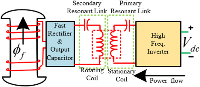
Figure 2.
Contactless power fed wound rotor field using the IPT.
-
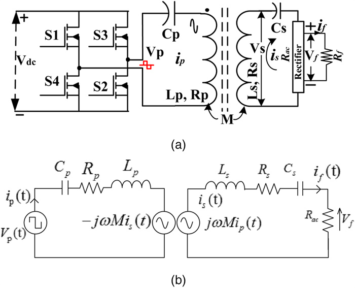
Figure 3.
(a) Basic series-series resonant IPT system. (b) Equivalent circuit referred to the transmitter side.
-

Figure 4.
(a) Resonant inverter supply to series LC resonating branch in primary winding (Cp, Lp, Rp) with a fixed DC source. (b) Scheme of using close-loop controlled DC-DC converters to achieve variable DC supply at the input side of the resonant inverter.
-
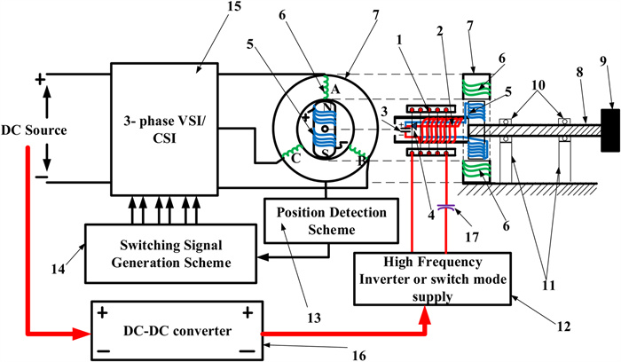
Figure 5.
Complete brushless DC/AC motor drive system with IPT-based contactless wound rotor field.
-
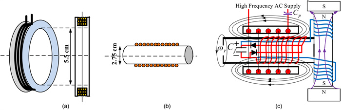
Figure 6.
Design of (a) primary stationary winding, (b) secondary or rotating winding, and (c) complete system with primary winding, secondary winding, and field winding.
-
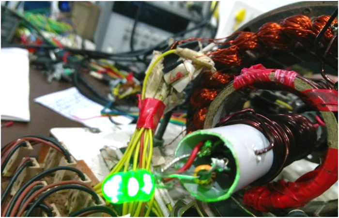
Figure 7.
Test was carried out in the previously developed multiconfiguration stator machine [46]. Concentrated winding of 25 μH inductance in primary and helical solenoid coil of 38.5 μH in the rotor are used. A green LED is connected to indicate rotor power transfer.
-
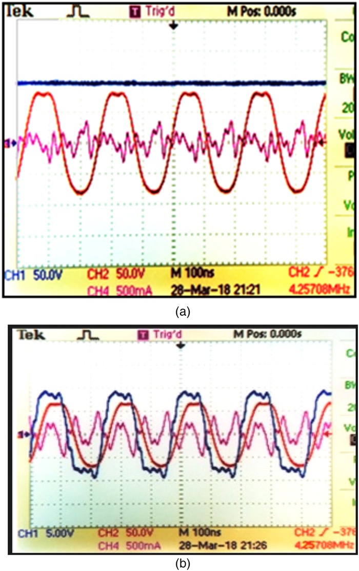
Figure 8.
Output AC voltage in the rotor (red) 50 V/div, probe 10X, output DC voltage in DC terminals of the rotor (blue) 50 V/div, probe 10X, and input resonant current (pink) with 500 mA/div and 1A/V current probe. Time scale 100 ns/div. (b) Output AC voltage in the rotor (red) 50 V/div, probe 10X, input AC voltage (blue) to RLC branch, 5 V/div, probe 1X, and input resonant current (pink) with 500 mA/div and 1A/V current probe. Time scale 100 ns/div.
-
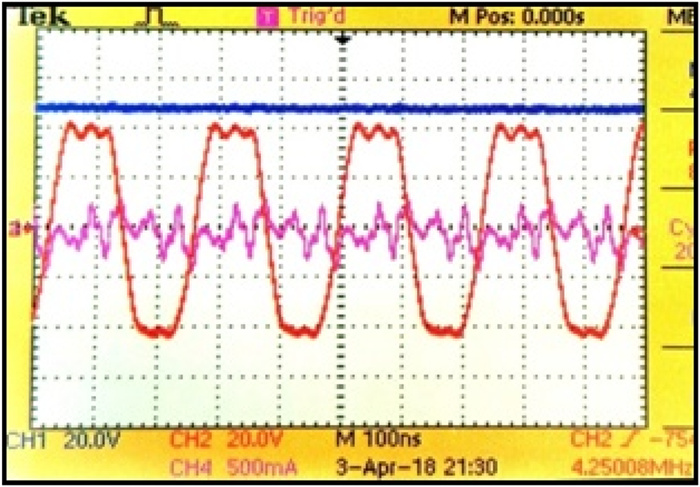
Figure 9.
Output AC voltage (red) in the rotor at 20 V/div, probe 10X, output DC voltage in the DC terminals of the rotor (blue) at 20 V/div, probe 10X, and input resonant current (pink) with 500 mA/div and 1A/V current probe. Time scale 100 ns/div. Maximum DC output at the open circuit was 49.8 V (only 10 MΩ probe resistance).
-
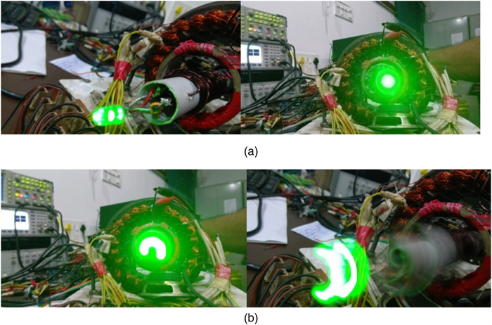
Figure 10.
(a) LED light intensity at a stationary rotor. (b) LED light intensity when rotated at approximately 500 rpm.
-
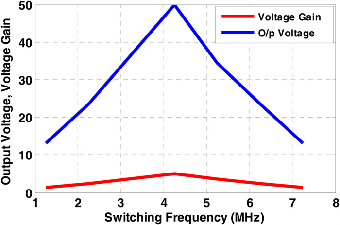
Figure 11.
Variation of rotor output dc voltage and voltage gain (Vo/Vinrms) with respect to the variation in the input switching frequency at input rms voltage of 9.950 Vrms.
-
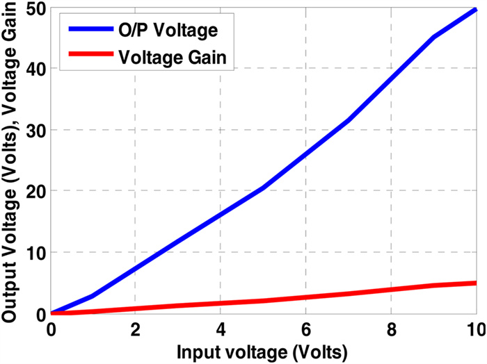
Figure 12.
Variation of no-load rotor output voltage with respect to input RMS voltage at a fixed frequency of 4.25 MHz.
Figures
(12)
Tables
(0)