-
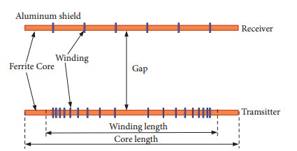
Figure 1.
Structure of inhomogeneous winding for loosely coupled transformers.
-
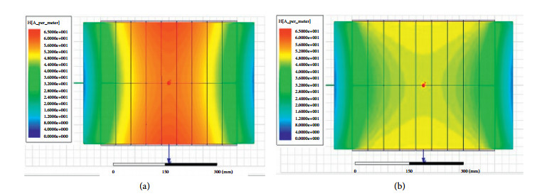
Figure 2.
Internal magnetic field. (a) Homogeneous winding. (b) Inhomogeneous winding.
-
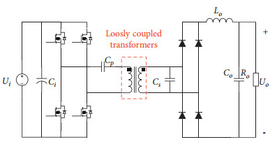
Figure 3.
Typical wireless power transfer system.
-
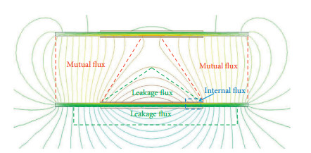
Figure 4.
Flux distribution of the solenoid structure.
-
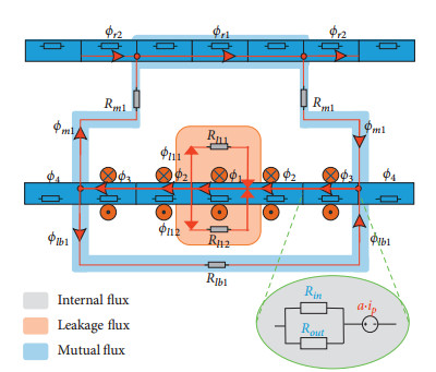
Figure 5.
Equivalent magnetic reluctance network.
-
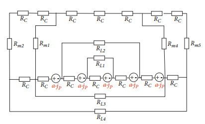
Figure 6.
Lumped magnetic reluctance model.
-
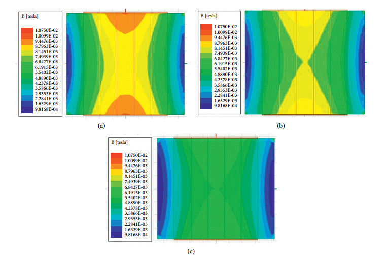
Figure 7.
Magnetic field distributions in core with different winding parameters. (a) Homogeneous winding (9 : 9 : 9 : 9 : 9). (b) Winding parameters (10 : 10 : 5 : 10 : 10). (c) Winding parameters (17 : 4 : 3 : 4 : 17).
-
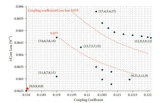
Figure 8.
Variation of core loss and coupling coefficient with different winding parameters.
-
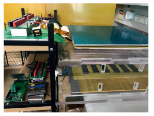
Figure 9.
Experimental setup for wireless power transfer under inhomogeneous winding.
-
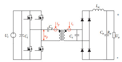
Figure 10.
The diagram of the setups for measuring.
-
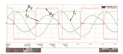
Figure 11.
Test waveforms of the system.
-
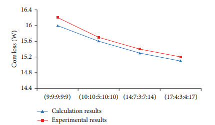
Figure 12.
Variation of core loss with different winding parameters.
-
Winding parameters Theoretical loss (W) Simulation loss (W) (9: 9: 9: 9: 9) 16.05 16.08 (10: 10: 5: 10: 10) 15.55 15.58 (17: 4: 3: 4: 17) 15.10 15.12 Table 1.
Comparison of core loss in theoretical and simulation results.
Figures
(12)
Tables
(1)