-
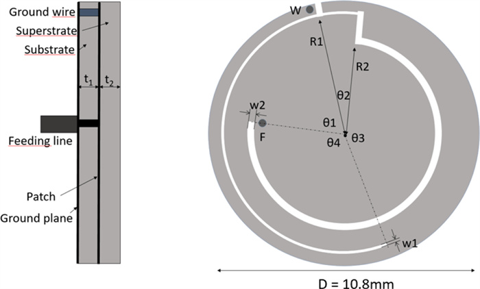
Figure 1.
The circular antenna.
-
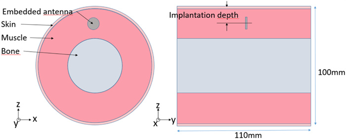
Figure 2.
The three-layer arm model.
-
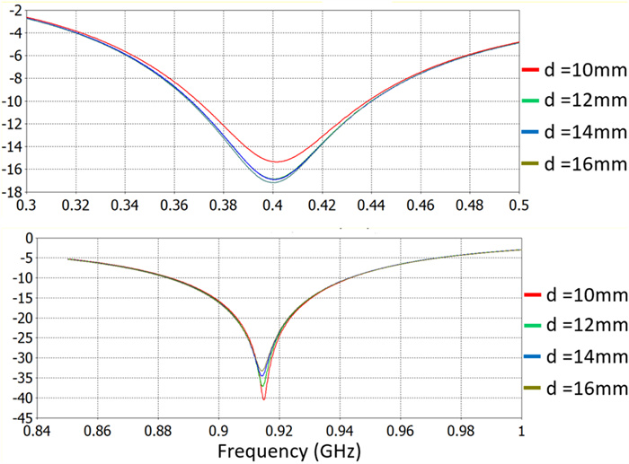
Figure 3.
Reflection coefficient of the antenna (at 400 MHz and at 915 MHz).
-
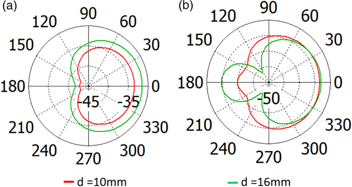
Figure 4.
2D radiation pattern of the antenna at 10 and 16 mm implantation depths ((a) at 400 MHz and (b) at 915 MHz).
-
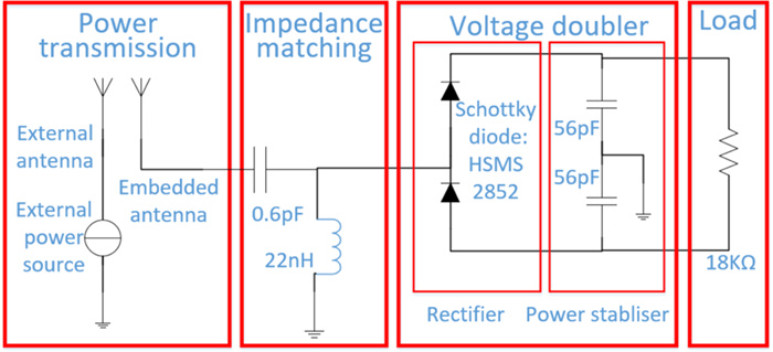
Figure 5.
Rectenna system structure (abstract).
-
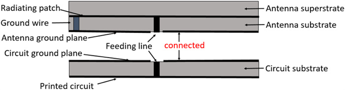
Figure 6.
Rectenna system structure (physical).
-
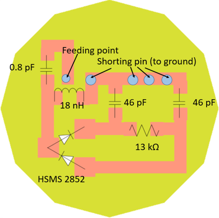
Figure 7.
Rectifying system pattern.
-
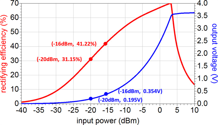
Figure 8.
Efficiency and output voltage results for different input power (rectifying efficiency = 41.22%, output voltage = 0.354 V with −16 dBm input power; rectifying efficiency = 31.15%, output voltage = 0.195 V with −20 dBm input power).
-
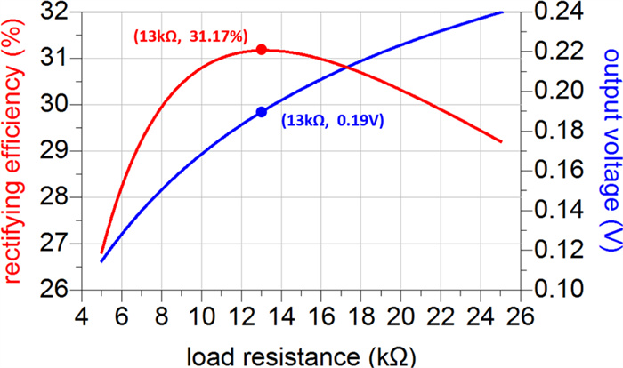
Figure 9.
Efficiency and output voltage for different load resistances (rectifying efficiency = 31.17%, output voltage = 0.19 V with 13 kΩ load resistance).
-
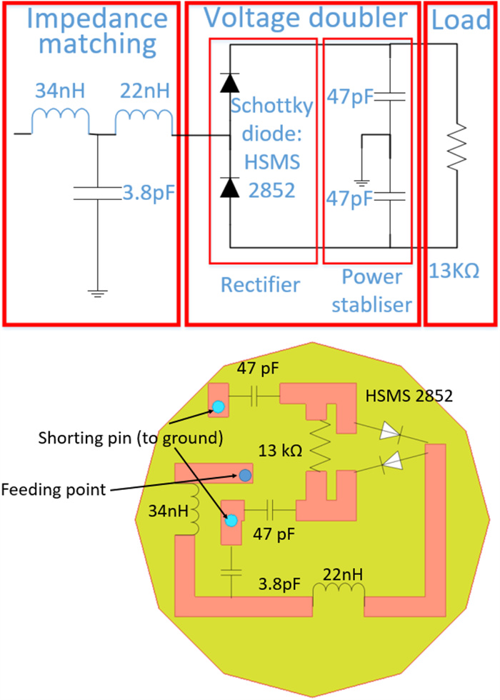
Figure 10.
Three-component rectifying system design.
-
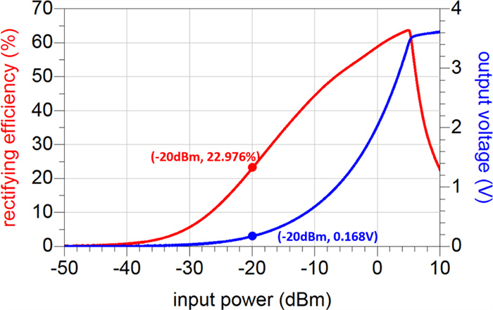
Figure 11.
Efficiency and output voltage results for three-component design (rectifying efficiency = 22.976%, output voltage = 0.168 V with −20 dBm input power).
-
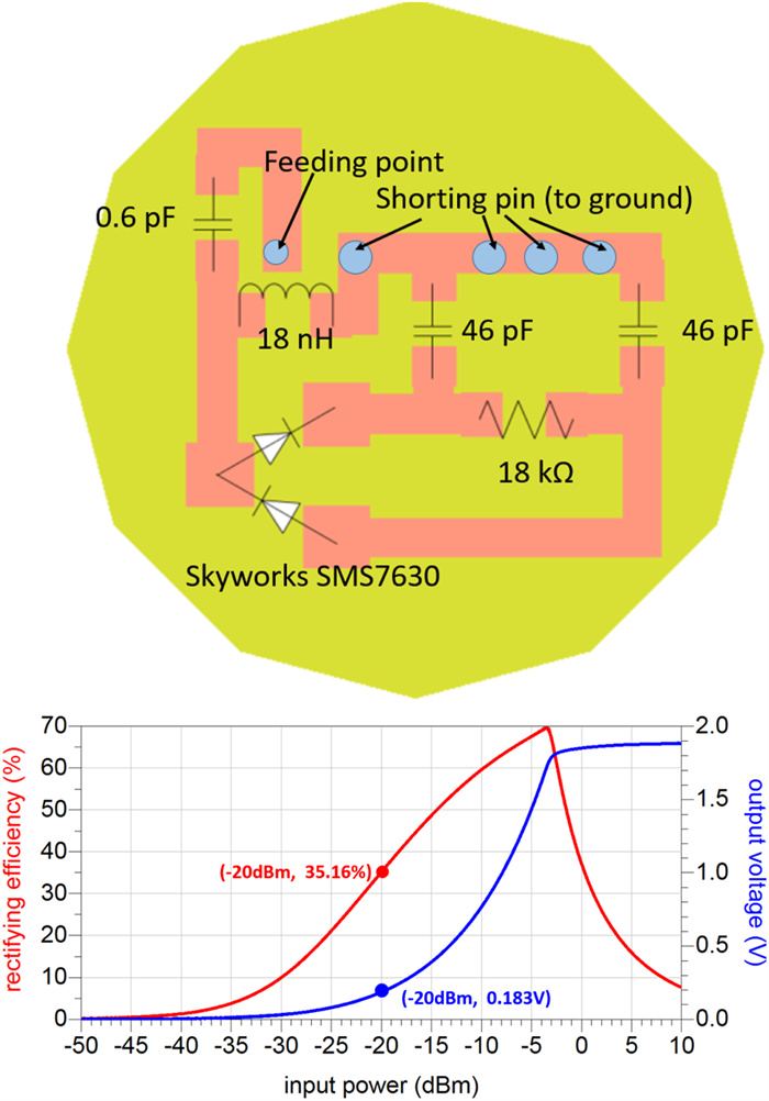
Figure 12.
Topology and rectifying results for Skyworks 7630 diode (rectifying efficiency = 35.16%, output voltage = 0.183 V with −20 dBm input power).
-
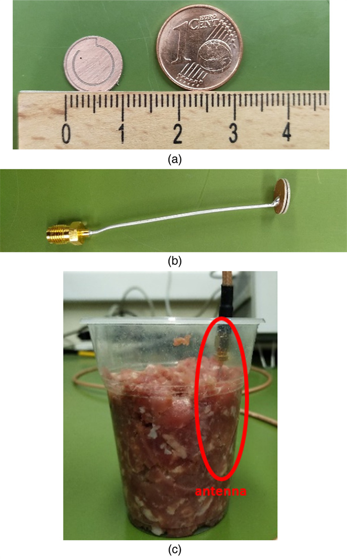
Figure 13.
(a) Fabricated antenna comparing with one euro cent, (b) complete antenna with coaxial cable and superstrate and (c) antenna embedded into minced pork.
-
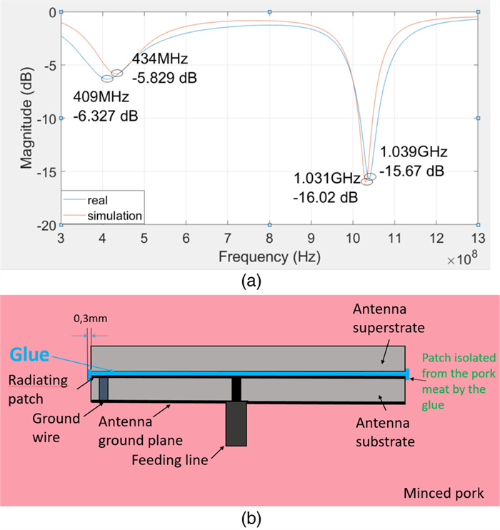
Figure 14.
(a) First measurement results and corresponding simulation when patch is isolated by glue and (b) corresponding simulation model.
-
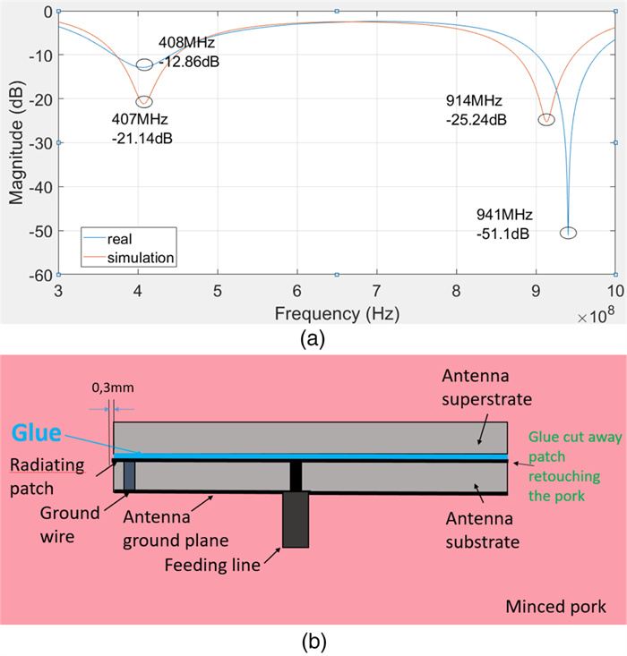
Figure 15.
(a) Second measurement results and corresponding simulation when patch is expose to the minced pork meat and (b) corresponding experimental model.
-
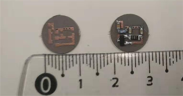
Figure 16.
Soldered and unsoldered circuits.
-
Parameter name Value (mm) Parameter name Value (°) R1 4.9 θ1 70 R2 3.76 θ2 18 w1 0.15 θ3 163 w2 0.32 θ4 109 t1 0.64 t2 0.64 D 10.8 Table 1.
Antenna parameters
-
Frequency Bone Muscle Skin 403 MHz ɛr 13.22 57.15 46.81 σ (S/m) 0.09 0.79 0.69 915 MHz ɛr 12.45 54.98 41.35 σ (S/m) 0.15 0.93 0.85 Table 2.
Dielectric constants of human tissue
-
1 g-average standard 10 g-average standard Implantation depth (mm) 10 mm 16 mm 10 mm 16 mm 403 MHz 15.38 mW 14.99 mW 72.22 mW 71.17 mW 915 MHz 14.08 mW 14.01 mW 86.33 mW 91.19 mW Table 3.
Maximum input power for the PIFA antenna
-
Table 4.
Low cost sensors and specific parameters
-
Transmission distance (mm) Rectifying efficiency (%) Voltage at load (V) Power at load (μW) 200 44.5 0.412 31.98 240 39.0 0.294 18.58 280 34.5 0.225 12.13 320 31.4 0.184 9.11 360 27.8 0.145 6.52 400 23.2 0.108 4.33 Table 5.
Received power at difference distances
Figures
(16)
Tables
(5)