-
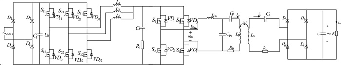
Figure 1.
Schematic diagram of the ICPT system based on the synchronous three-phase triple-parallel Buck converter.
-
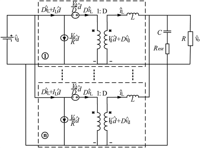
Figure 2.
Small-signal model of a synchronous three-phase triple-parallel parallel Buck converter.
-
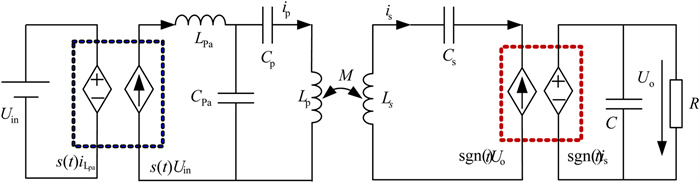
Figure 3.
Norton equivalent schematic diagram of the ICPT system.
-
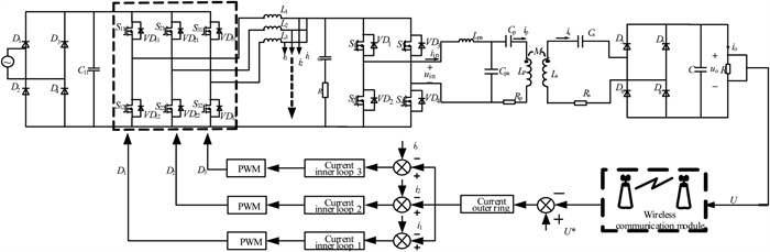
Figure 4.
Principle of current sharing and constant voltage output voltage control of the ICPT system.
-
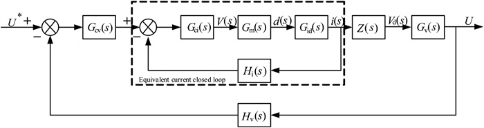
Figure 5.
Flow-sharing constant-voltage closed-loop output control block diagram for the ICPT system.
-
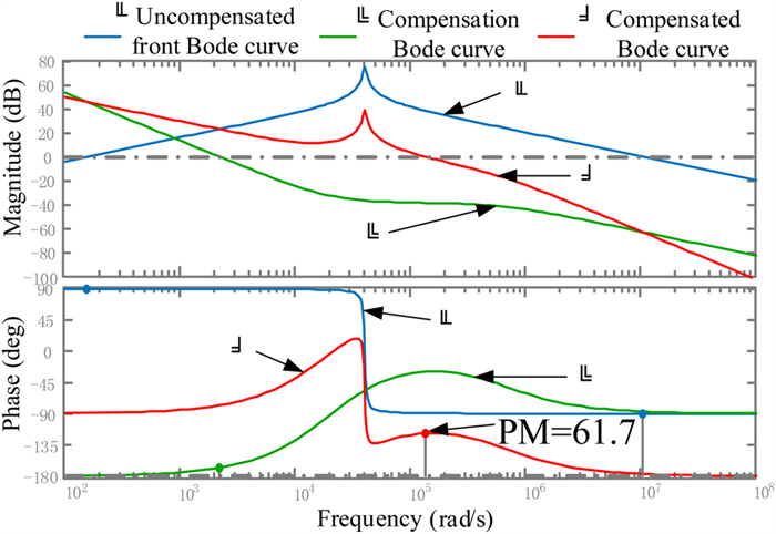
Figure 6.
Current loop frequency characteristic simulation curve.
-
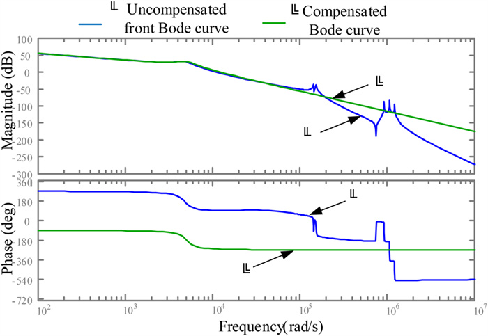
Figure 7.
Bode diagram before and after system fitting.
-
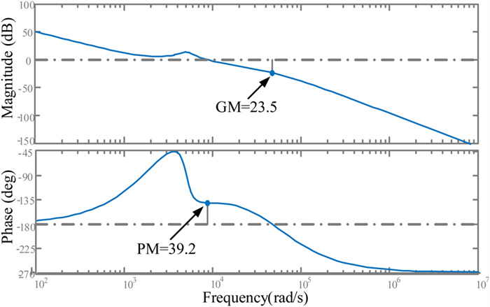
Figure 8.
Open-loop gain Bode diagram of the system with the voltage loop compensation network.
-
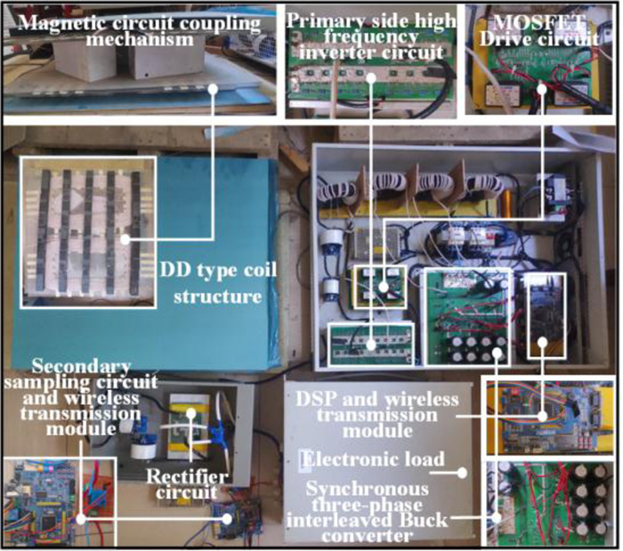
Figure 9.
Experimental platform of the ICPT system with current sharing and constant voltage output.
-
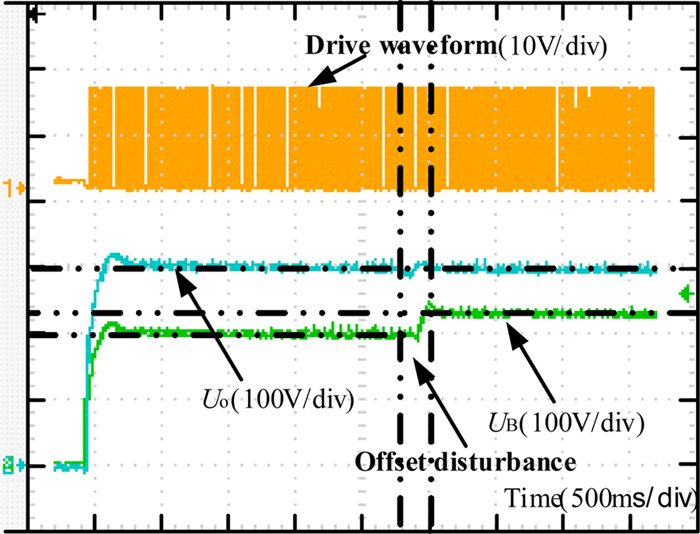
Figure 10.
Drive and output voltage waveforms of the output voltage and the synchronous three-phase triple-parallel Buck converter.
-
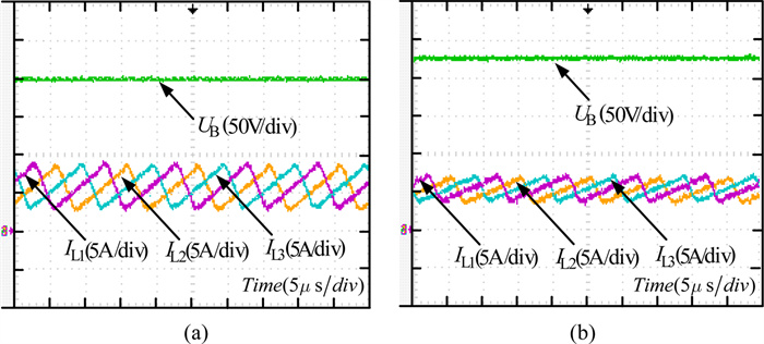
Figure 11.
Output voltage and inductor current waveforms of the synchronous three-phase triple-parallel Buck converter before and after coupling coefficient variation. (a) Before coupling coefficient variation. (b) After coupling coefficient variation.
-
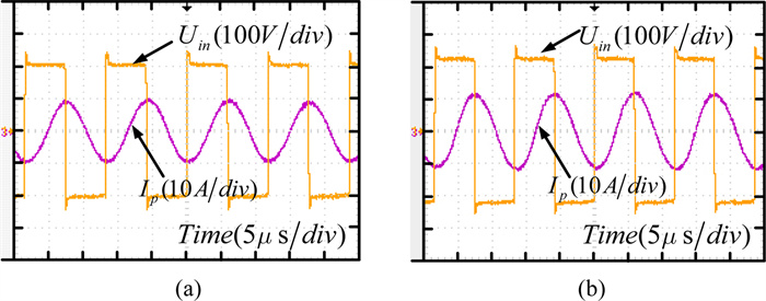
Figure 12.
Output voltage and primary side coil current waveform of the inverter before and after coupling coefficient variation. (a) Before coupling coefficient variation. (b) After coupling coefficient variation.
-
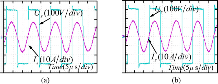
Figure 13.
Voltage and current waveform of the secondary side pick-up before and after coupling coefficient variation. (a) Before coupling coefficient variation. (b) After coupling coefficient variation.
-
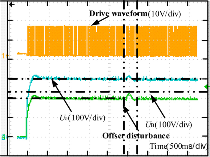
Figure 14.
Drive and output voltage waveforms of the system output voltage and the synchronous three-phase triple-parallel Buck converter.
-
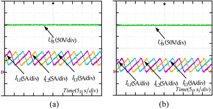
Figure 15.
Output voltage and inductance current waveforms of the synchronous three-phase triple-parallel Buck converter under full and half load conditions. (a) Full load. (b) Half load.
-
Parameter Value Parameter Value C11/μF 2050 Cpa/μF 0.0762 L1/μH 77 Cp/μF 0.018 L2/μH 77 Lp/μH 240 L3/μH 77 Ls/μH 240 C1/μF 23.5 Cs/μF 0.0146 D 0.75 C/μF 68 f1/kHz 100 R/Ω 27.3 Lpa/μH 46 k 0.3 Table 1.
Parameters of ICPT system
-
Three-phase Buck circuit Inverter circuit Secondary rectifier circuit Mosfet (six)
CREE-C2M0080120DMosfet (four)
CREE-C2M0080120DDiode (six)
FAIRCHILD-RURG8060Table 2.
Major components
-
Fault tolerance Switch tube stress Voltage ripple Power density Redundancy Volume Cost Single-phase Buck converter No Larger Larger Larger Lower A S Three-phase triple-parallel Buck converter Yes Smaller Smaller Smaller Higher < 3A < 3S Table 3.
Comparison of sign-phase Buck converter and three-phase triple-parallel Buck converter
Figures
(15)
Tables
(3)