-
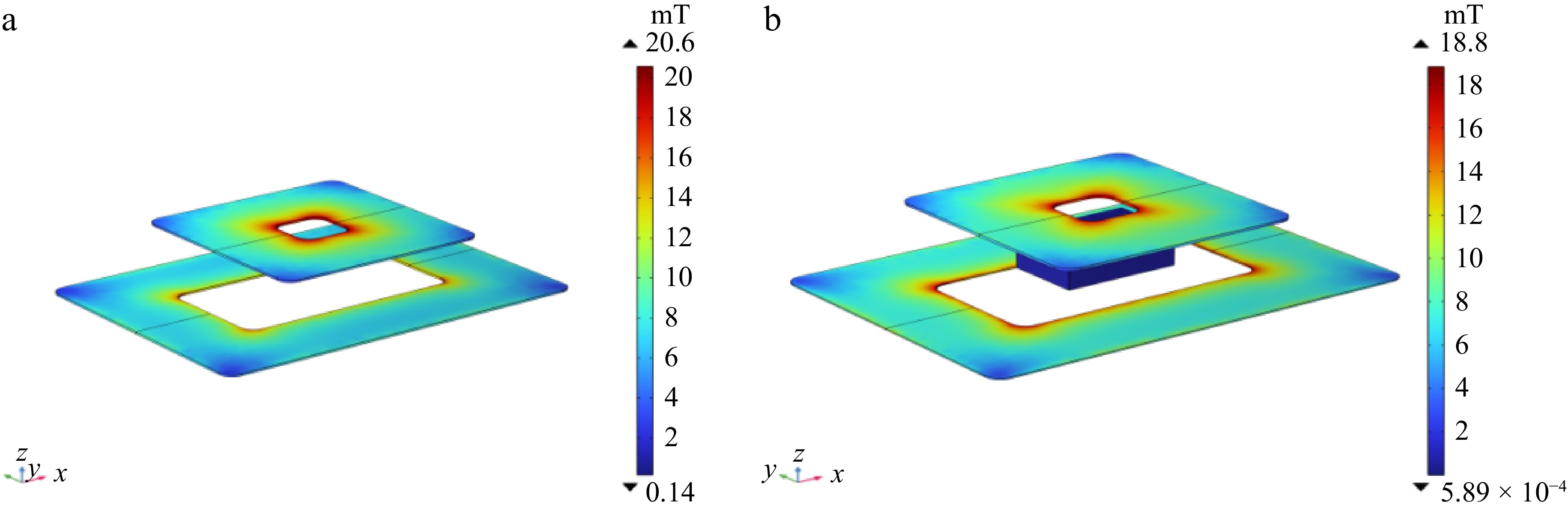
Figure 1.
The simulation model of the electromagnetic coupling mechanism: (a) in the absence of foreign objects, (b) in the presence of foreign objects.
-
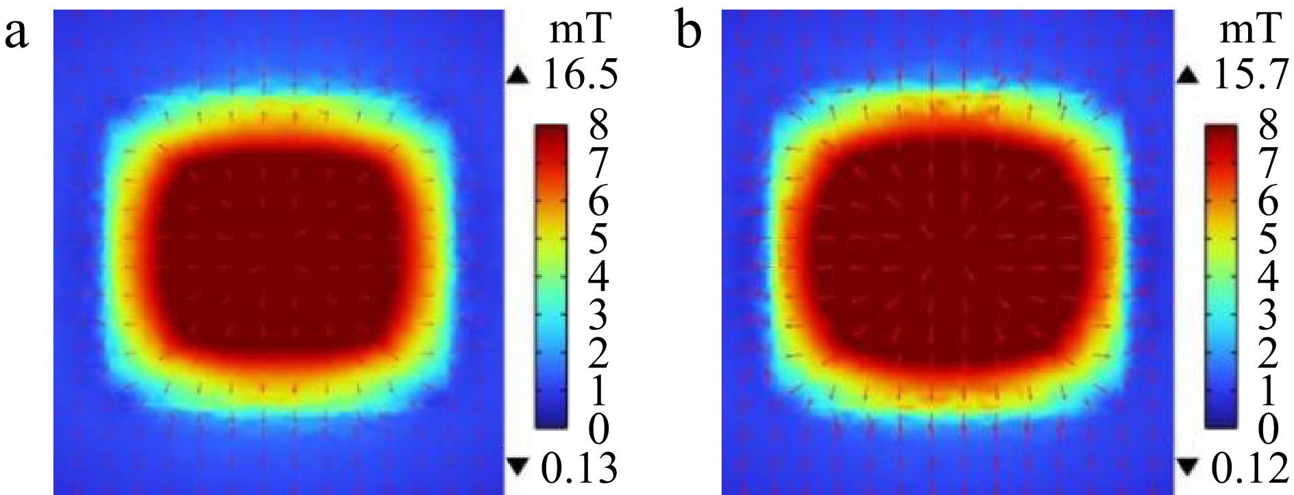
Figure 2.
Magnetic field intensity of the receiving coil: (a) in the state without foreign objects, (b) in the state with foreign objects.
-
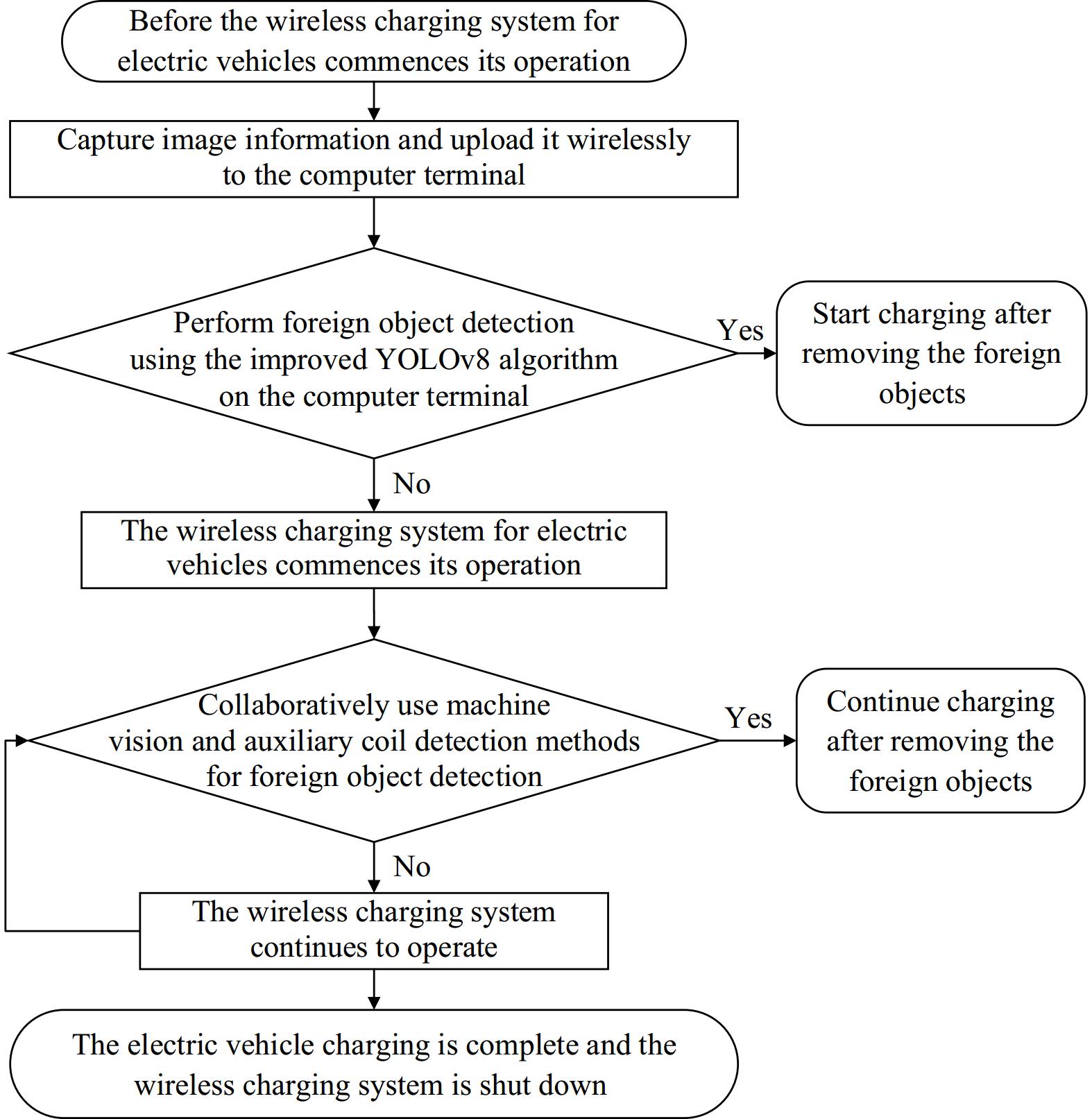
Figure 3.
Overall flowchart of metal foreign body detection implementation plan.
-
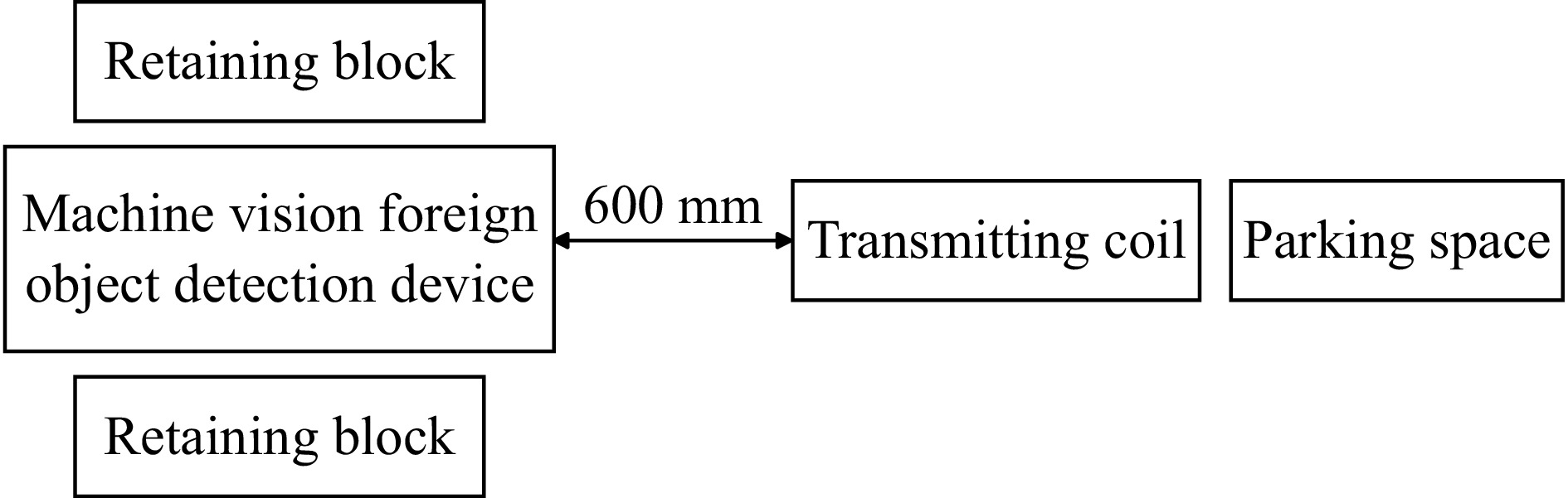
Figure 4.
Installation diagram of machine vision foreign object detection device.
-
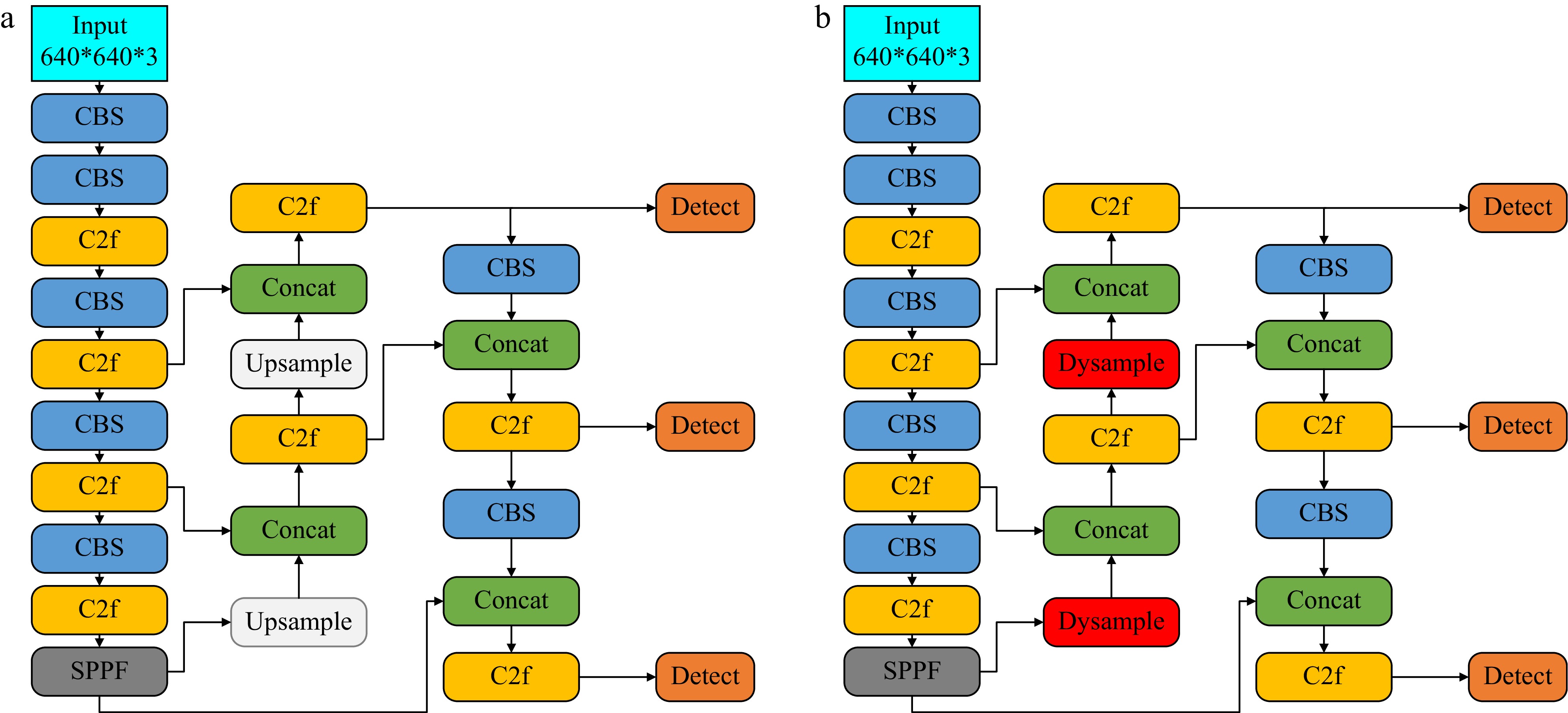
Figure 5.
Model structure diagram: (a) YOLOv8, (b) improved YOLOv8.
-
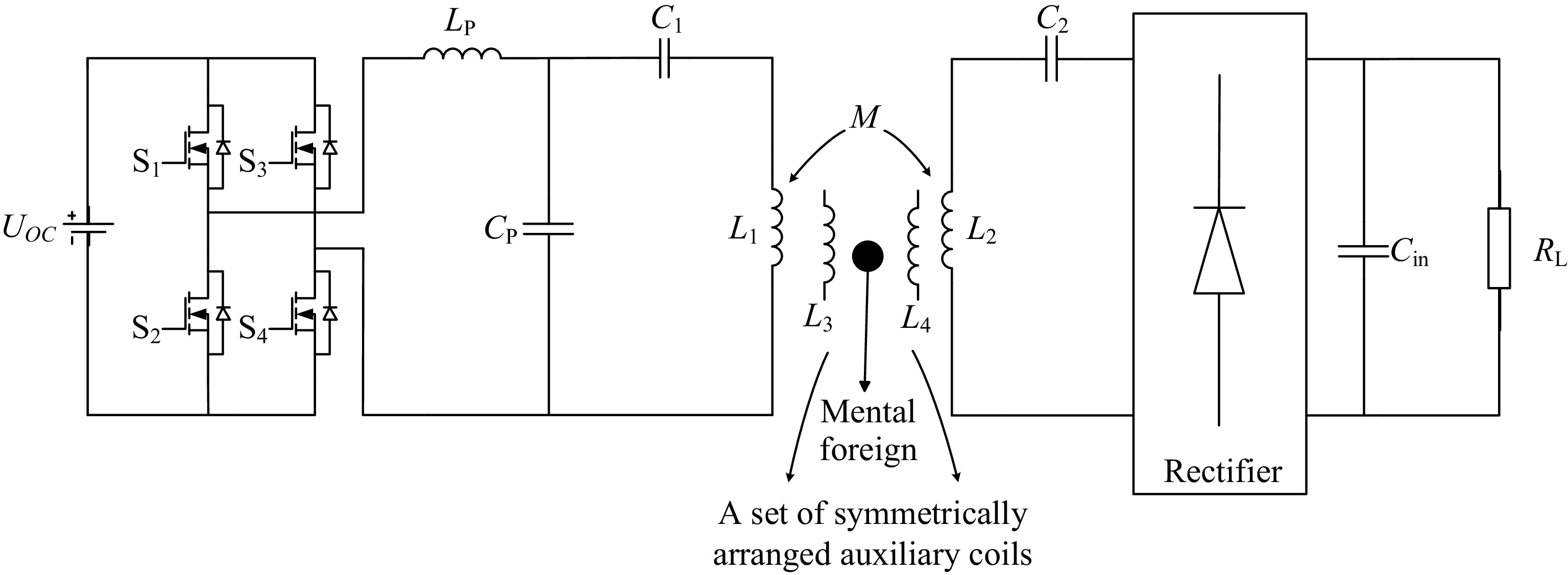
Figure 6.
Equivalent circuit of LCC-S wireless power transfer system.
-
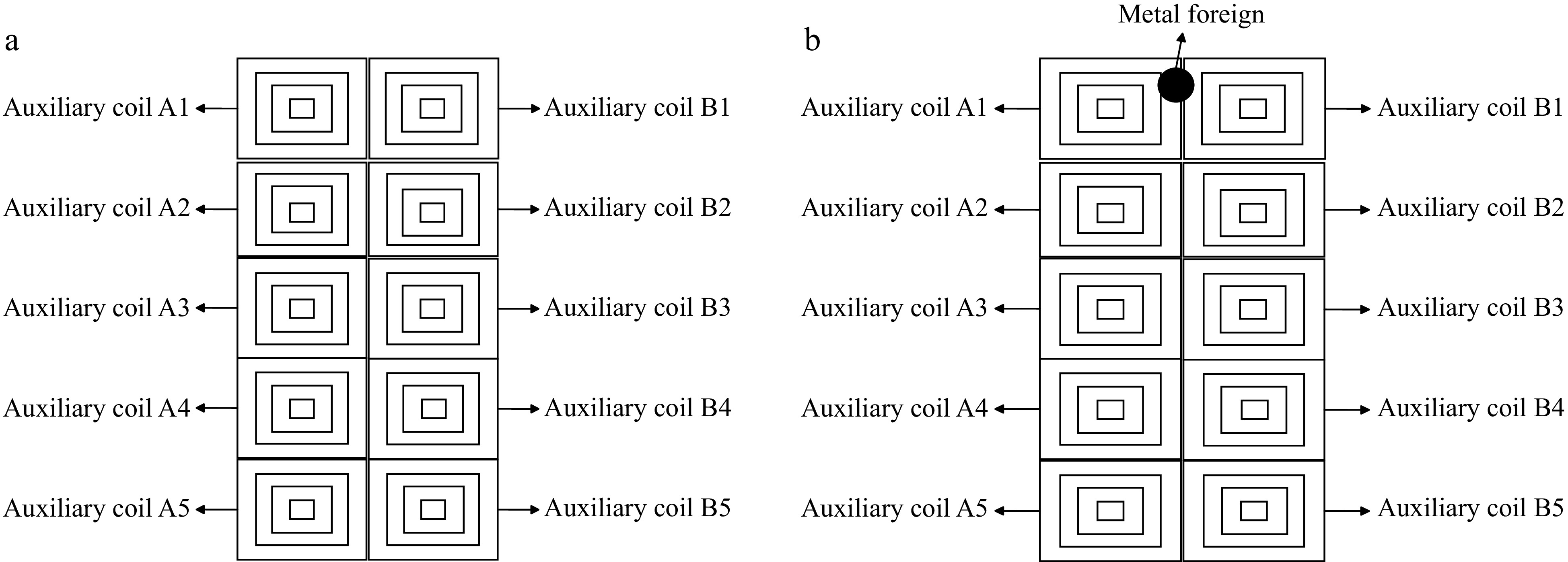
Figure 7.
Structure diagram of auxiliary coil: (a) without foreign object, (b) with foreign object.
-
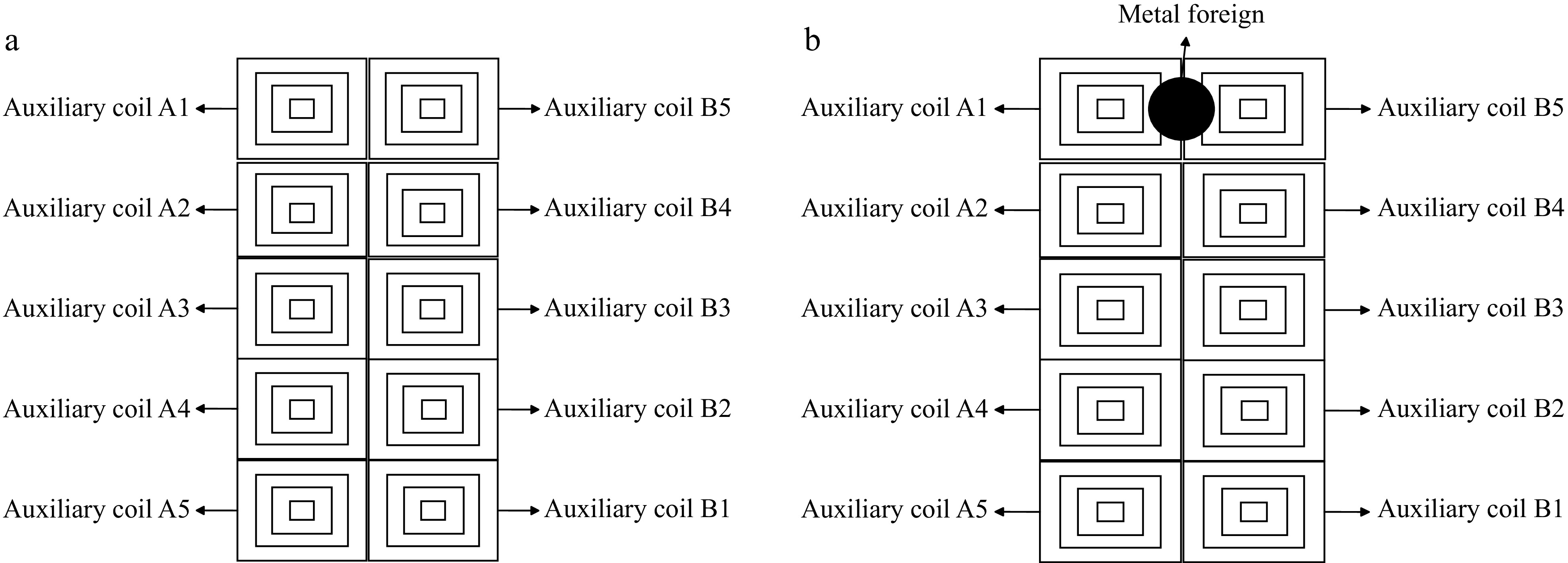
Figure 8.
Structural diagram of improved auxiliary coil: (a) without foreign object, (b) with foreign object.
-
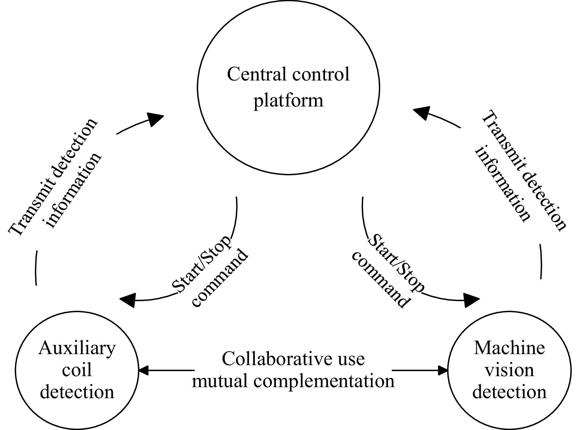
Figure 9.
Collaborative optimization-based foreign body detection method.
-
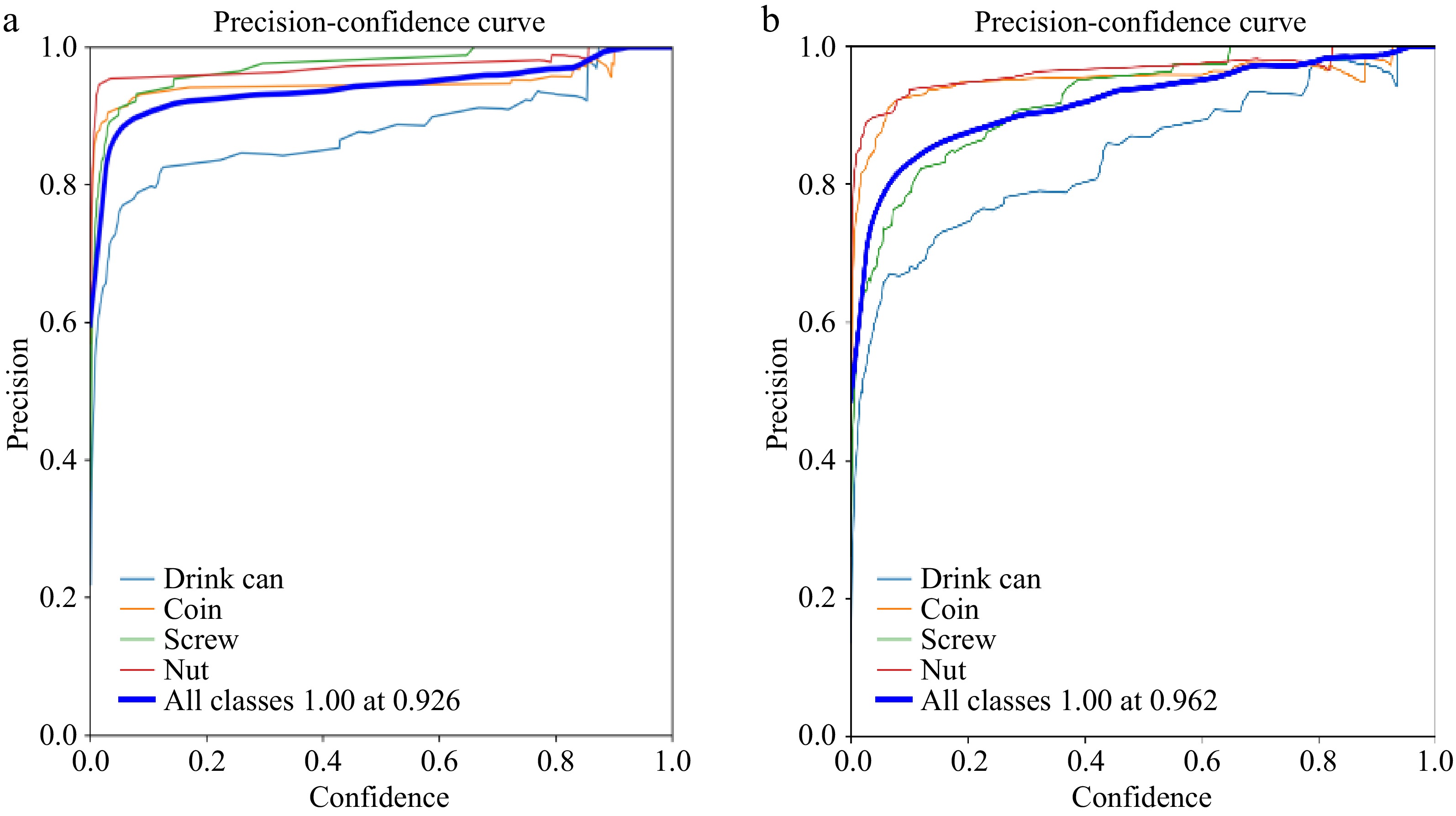
Figure 10.
Precision curve: (a) YOLOv8 model, (b) improved YOLOv8 model.
-
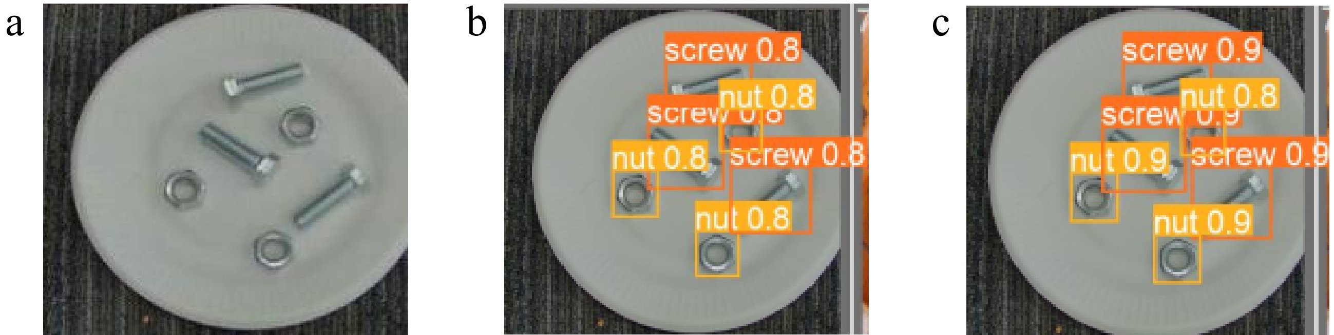
Figure 11.
Actual detection effect of screws and nuts: (a) original image, (b)YOLOv8n, (c) improved YOLOv8n.
-
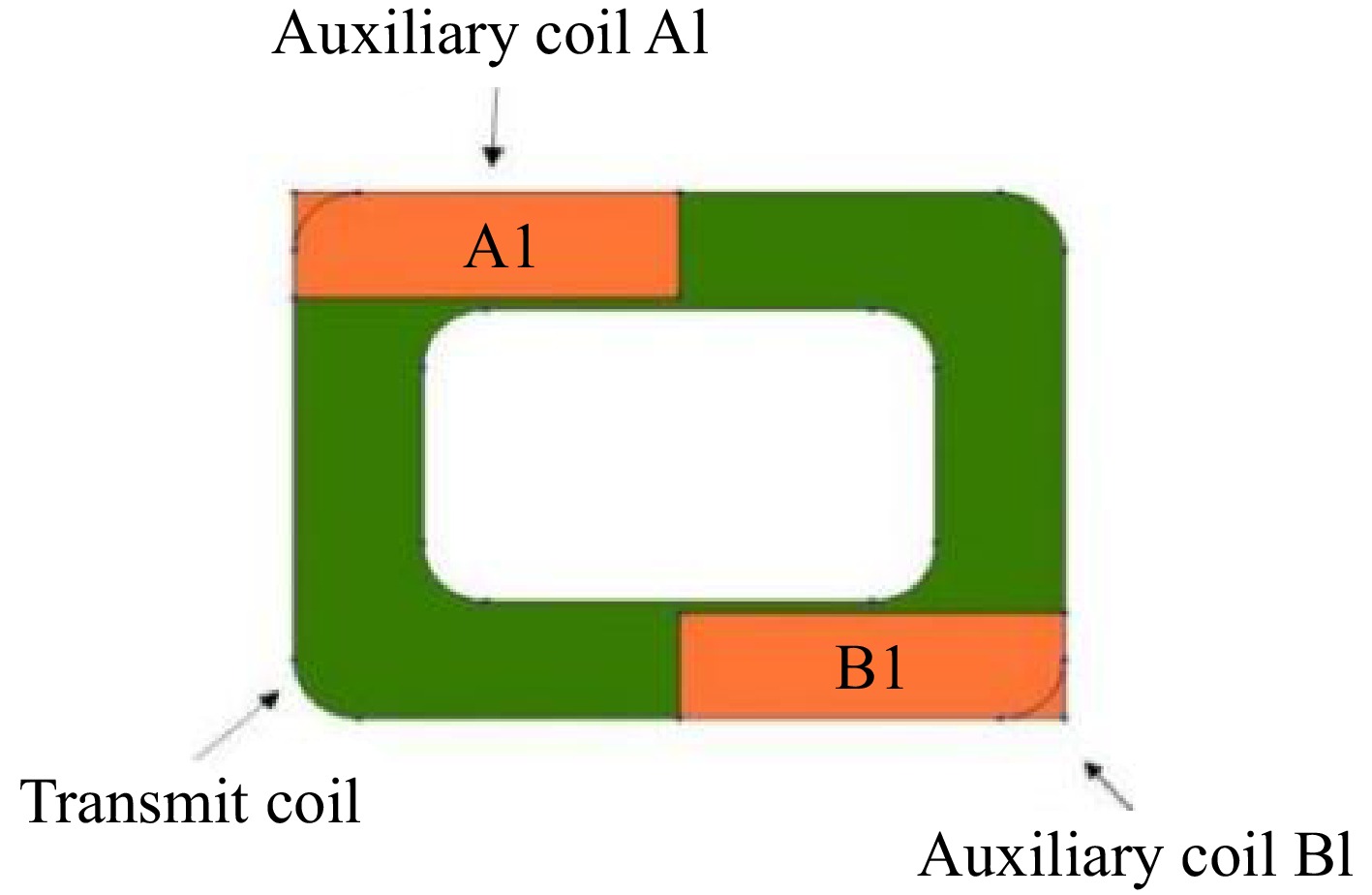
Figure 12.
Magnetic field simulation model.
-
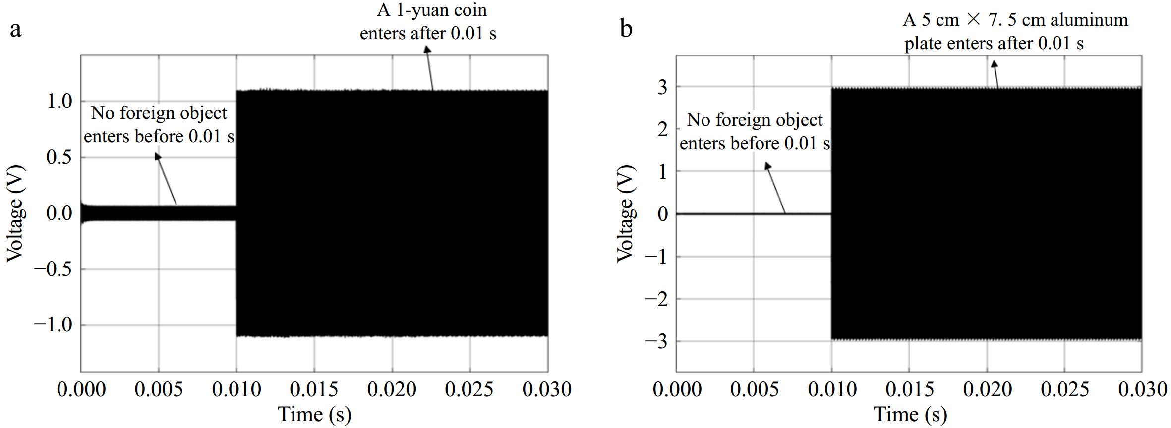
Figure 13.
Voltage fluctuation caused by foreign objects with a load of 19 Ω: (a) a 1-yuan coin, (b) a 5 cm × 7.5 cm aluminum plate.
-
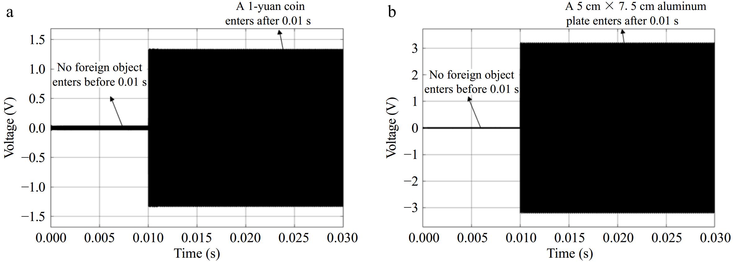
Figure 14.
Voltage fluctuation caused by foreign objects with a load of 15 Ω: (a) a 1-yuan coin, (b) a 5 cm × 7.5 cm aluminum plate.
-
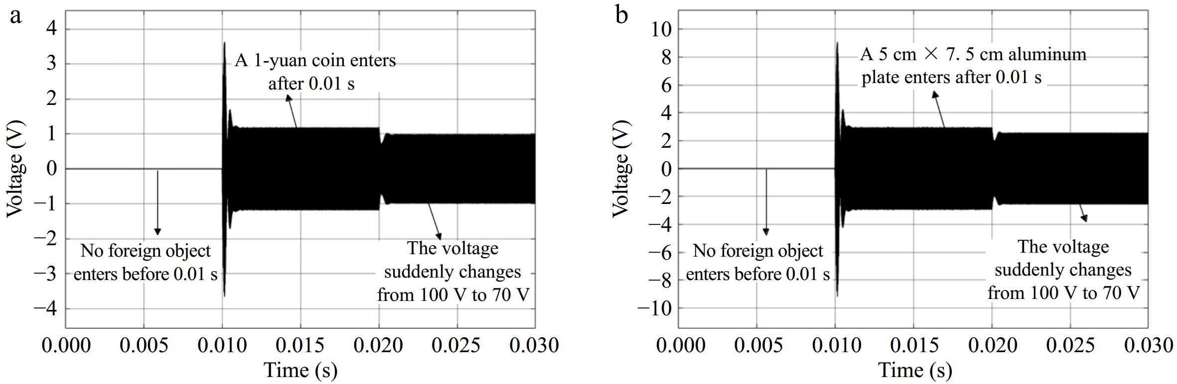
Figure 15.
Voltage fluctuation caused by system input voltage variation: (a) a 1-yuan coin, (b) a 5 cm × 7.5 cm aluminum plate.
-
Parameters Values Primary coil size (mm) 580 × 420 Primary coil wire diameter (mm) 5 Number of turns of primary coil 15 Secondary coil size (mm) 320 × 320 Secondary coil wire diameter (mm) 5 Number of turns of secondary coil 15 Iron material dimensions (mm) 150 × 100 × 80 Distance between primary and secondary coils (mm) 150 Current (A) 100 Table 1.
Simulation parameters of the electromagnetic coupling mechanism.
-
Parameters Values UOC/(V) 100 Initial value of system load RL/Ω 19 LP (μH) 7 CP (nF) 452 C1 (nF) 91 L3 (μH) 70 L1 (μH) 103.5 L2 (μH) 80 C2 (nF) 85 Cin (μF) 50 M (μH) 25 L4 (μH) 60 Table 2.
System simulation circuit parameters.
-
Parameters Values Auxiliary coil turns 4 Auxiliary coil wire diameter 5 Auxiliary coil size (mm) 30 × 9 Primary coil size (mm) 580 × 420 Primary coil diameter (mm) 5 Number of turns of primary coil 15 Secondary coil size (mm) 320 × 320 Secondary coil wire diameter (mm) 5 Auxiliary coil turns 4 Number of turns of secondary coil 15 Table 3.
Electromagnetic simulation model parameters.
Figures
(15)
Tables
(3)