-
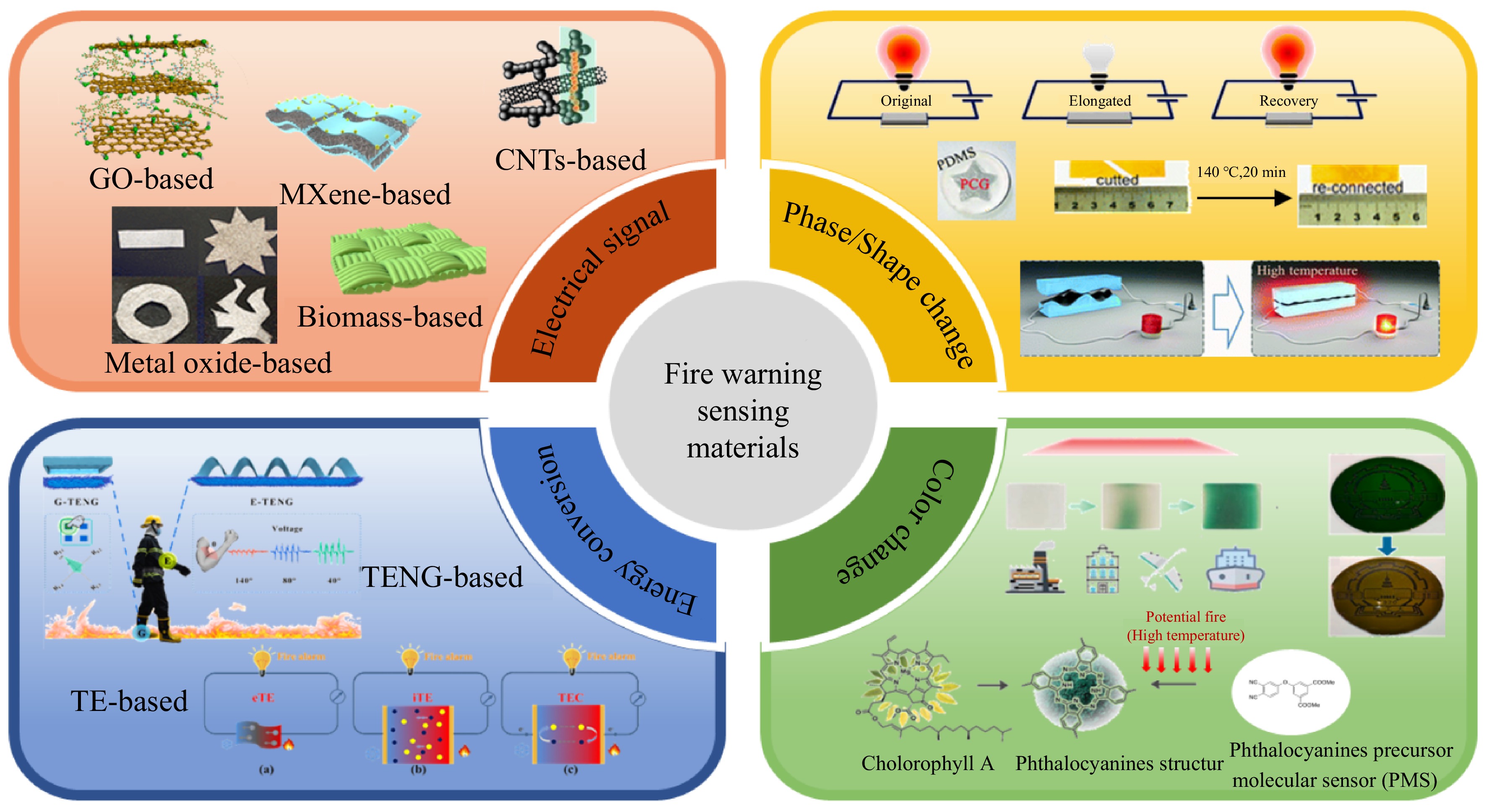
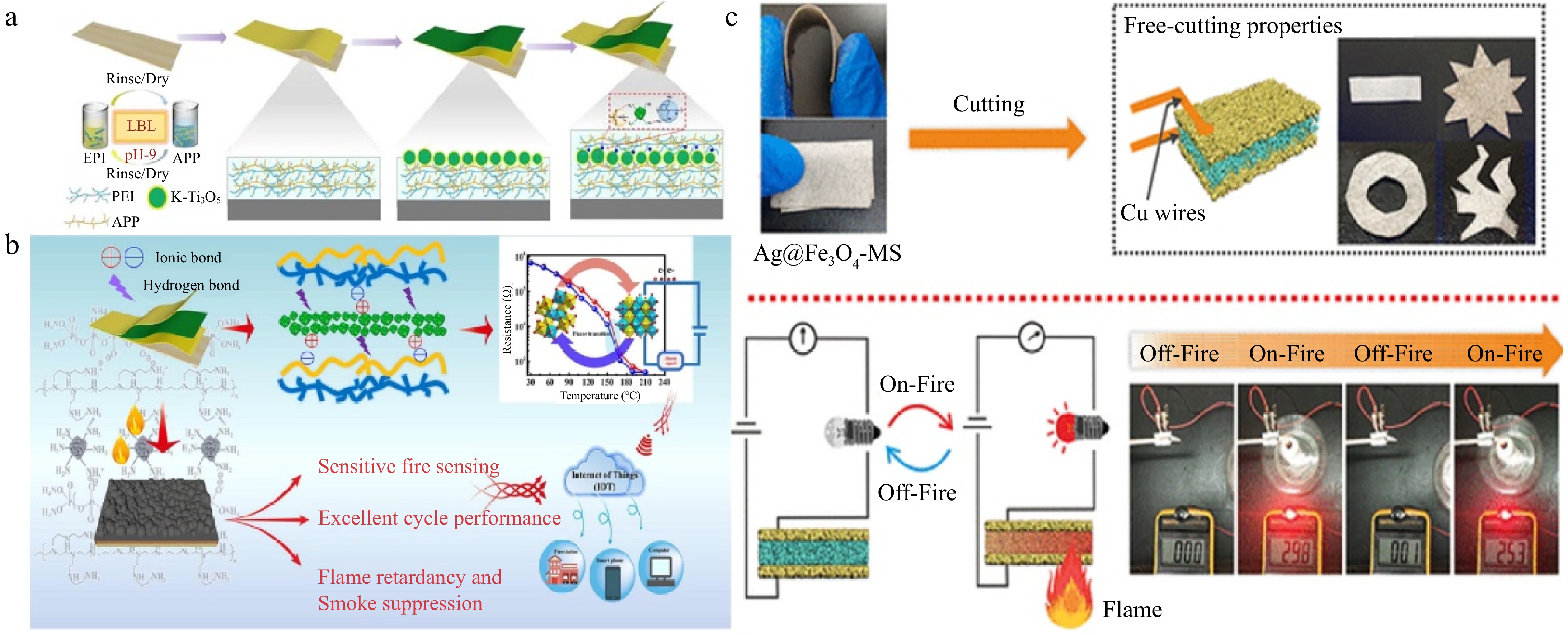
Figure 1.
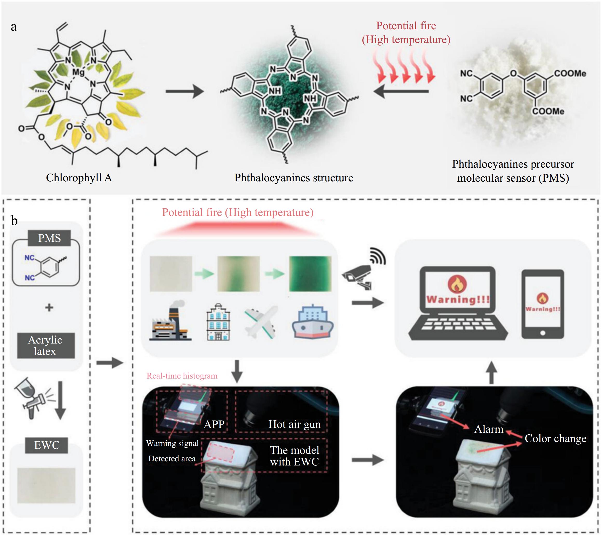
Research progress of sensing materials for fire warning. The cross-linked network of Tri-molecular compounds containing GO[17]. Structure diagram of C-MXene-coating in the early stage of a fire[18]. Conductive networks are formed by the carbonization of CB@KF[19]. The mechanical flexibility of Ag@Fe3O4-MS[20]. Nylon-cotton (NYCO) blend fabrics[21]. The phase change gel embedded in a polydimethylsiloxane (PDMS) encapsulant[22]. Using LED indicators to evaluate the conductivity of the sample in its initial state, stretched state, and shape-restored state[23]. Schematic illustration of the high-temperature or early fire-warning process of the assembled sensor[22]. Early fire-warning processes of PMS color change sensor and the remote monitoring alarm APP designed by the image recognition algorithm[24]. Design inspiration for molecular sensors[24]. The color of the PMF at 20 and 80 °C[25]. Mechanisms of the three types of heat-to-electricity energy conversion[16]. Emergency Gesture (E-TENG) sensor and Gait recognition (G-TENG) sensor[26].
-
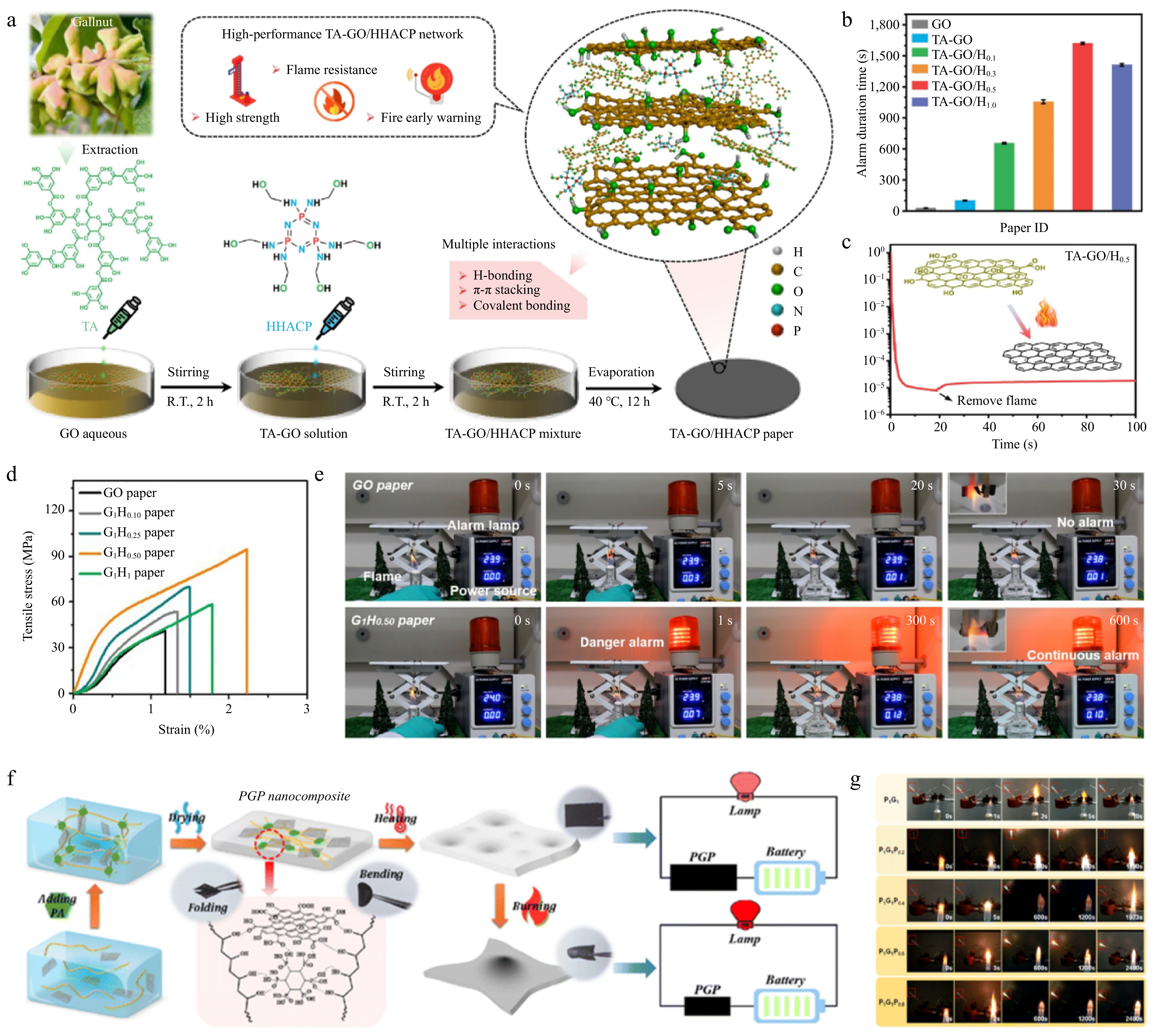
Figure 2.
(a) Schematic diagram of the preparation process of the nacre inspired TA-GO/HHACP hybrid network[17]. (b) Fire-alarm duration of graphene oxide based nanocomposite paper[17]. (c) Resistance change of TA-GO/H0.5 paper under flame attack and after extinguishing[17]. (d) Tensile stress-strain curves of pure GO paper and various GO/HCPA composite papers[31]. (e) Photo of flame detection process of GO paper and G1H0.50 paper[31]. (f) Process and conceptual design of PGP composite films prepared by water evaporation induced self-assembly method[32]. (g) Snapshot of LED lamp when PGP composite film burns[32].
-
-
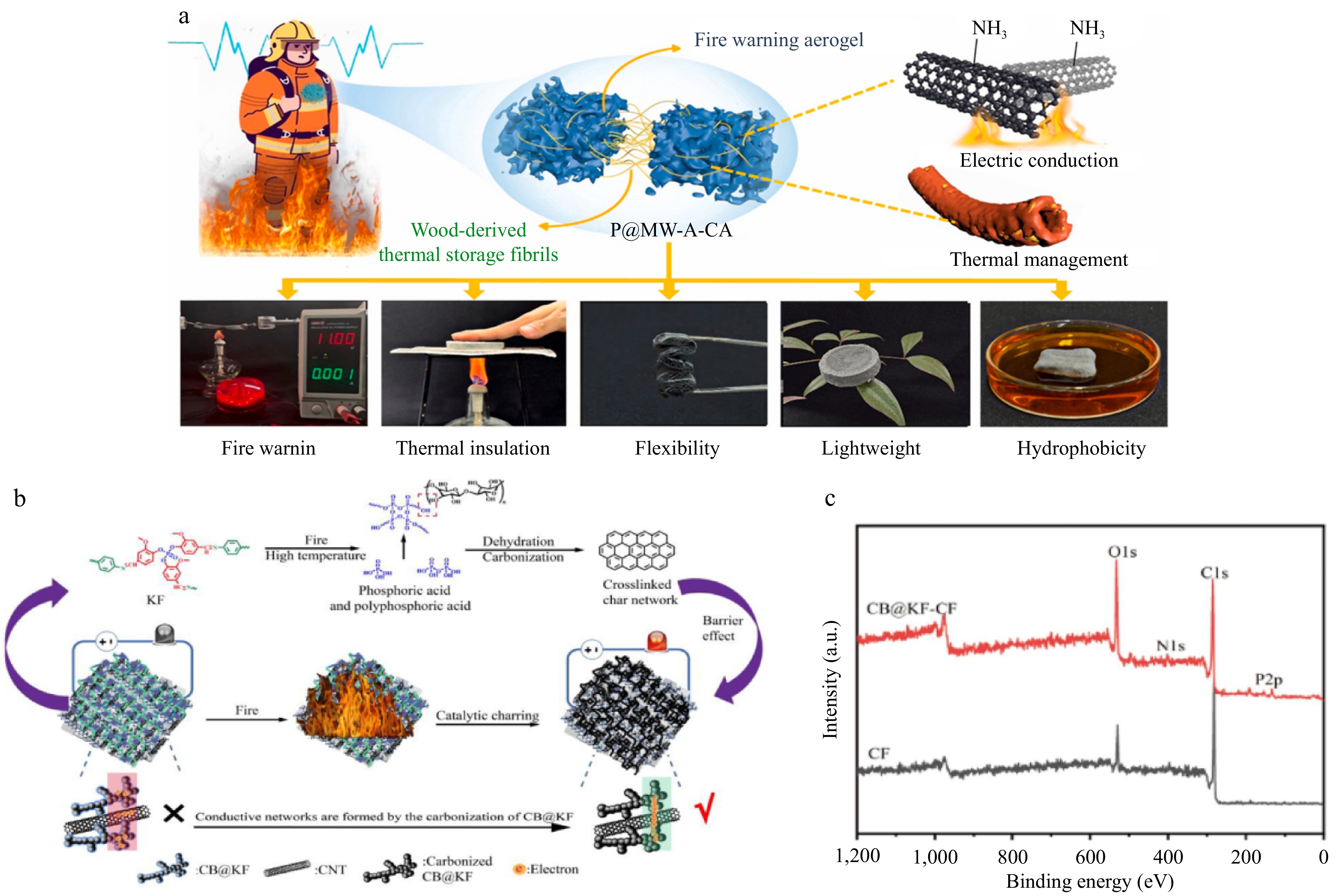
Figure 4.
(a) PEG-@ wood powder/carbon nanotubes/calcium alginate composite aerogel and its application in firefighting clothing[39]. (b) CB@KF-CF fire-alarm mechanism and flame retardant mechanism scheme[19]. (c) XPS survey spectra of the residual chars of CF and CB@KF-CF after fire-warning test[19].
-
-
-
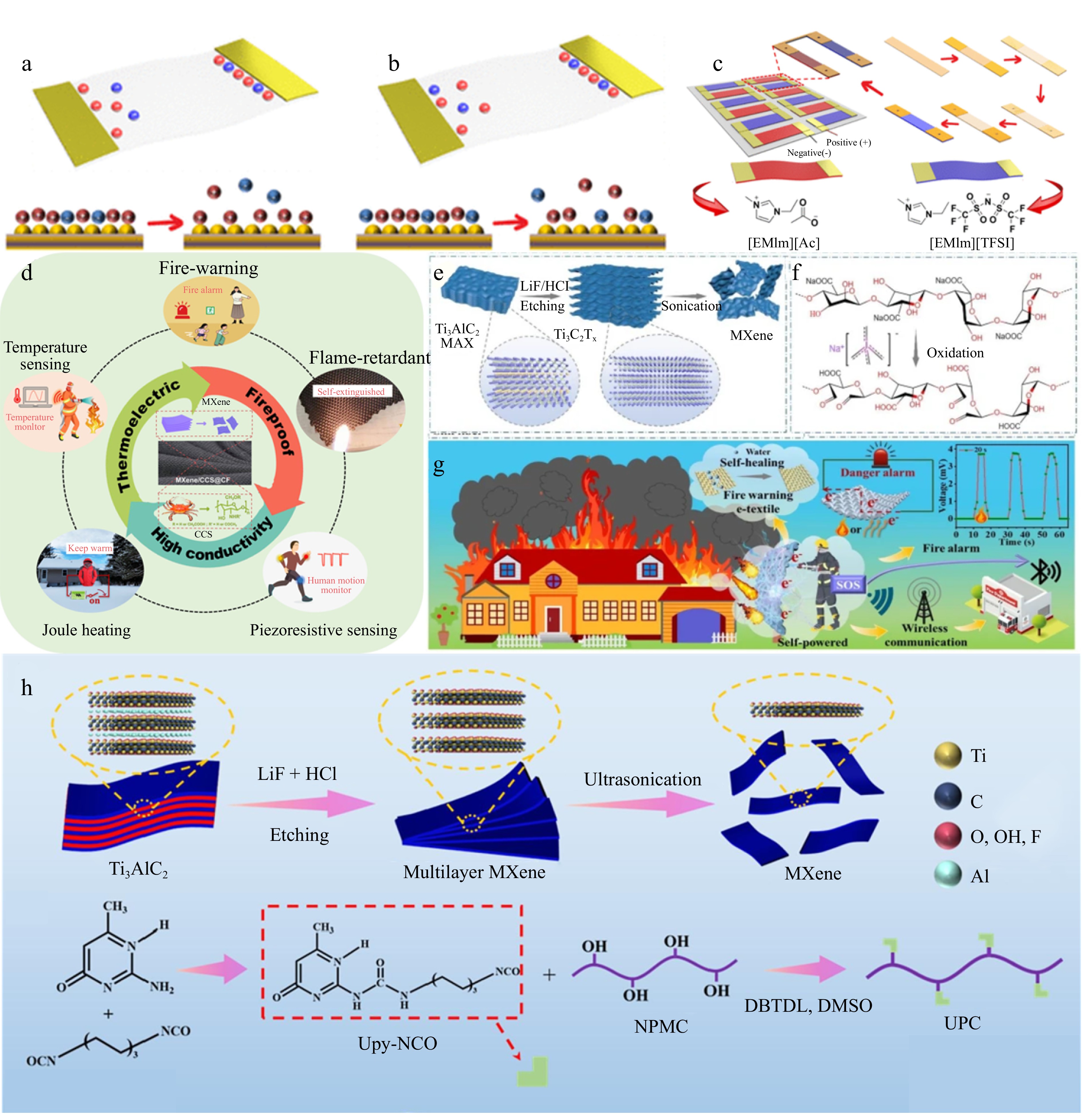
Figure 7.
Schematic illustration of ion desorption of (a) [EMIm][TFSI], and (b) [EMIm][Ac][48]. (c) Typical fabrication process of the single TE unit, TE module based on the connection of [EMIm][Ac] (p-type) and [EMIm][TFSI] (n-type) TE units in series[48]. (d) Design strategy of MXene/CCS@CF; schematic illustration of the application for MXene/CCS@CF including temperature sensing, fire-warning, flame retardancy, piezoresistive sensing, and joule heating performance[50]. (e) The etching process of MXene[50]. (f) Preparation mechanism diagram of OSA[50]. (g) Schematic view of the SS/OSA@MXene TE fiber-based self-powered high-temperature warning sensor simultaneously realized the early high-temperature warning and self-healing functions without external power supply in firefighting clothing[50]. (h) Synthesis rout of MXene and UPC. Fabrication route of MFNC[50].
-
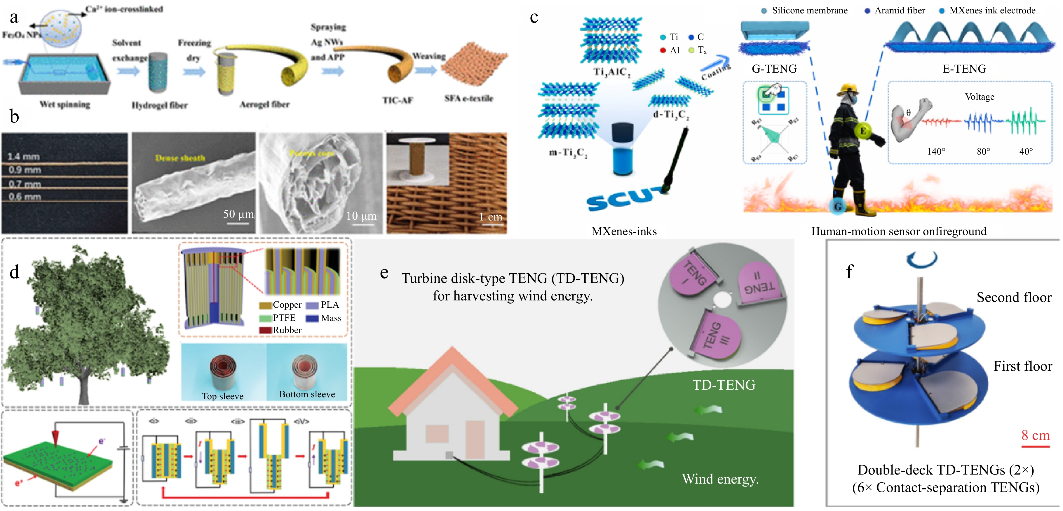
Figure 8.
(a) TIC-AF and SFA electronic textile manufacturing schematic[57]. (b) Photographs of TIC-AF and TIC-AF surfaces and cross sections manufactured with different diameters[57]. (c) The construction drawing of TENG sensors for monitoring human motion on fireground. Patterned inks electrodes: MXenes-inks; the E-TENG sensor and G-TENG sensor[26]. (d) Schematic diagram of MC-TENG for collecting kinetic energy of branch shaking[58]. (e) Application scenarios and overview of TD-TENG for wind energy harvesting[59]. (f) Schematic diagram of double-layer TD-TENG based on six TENG units[59].
-
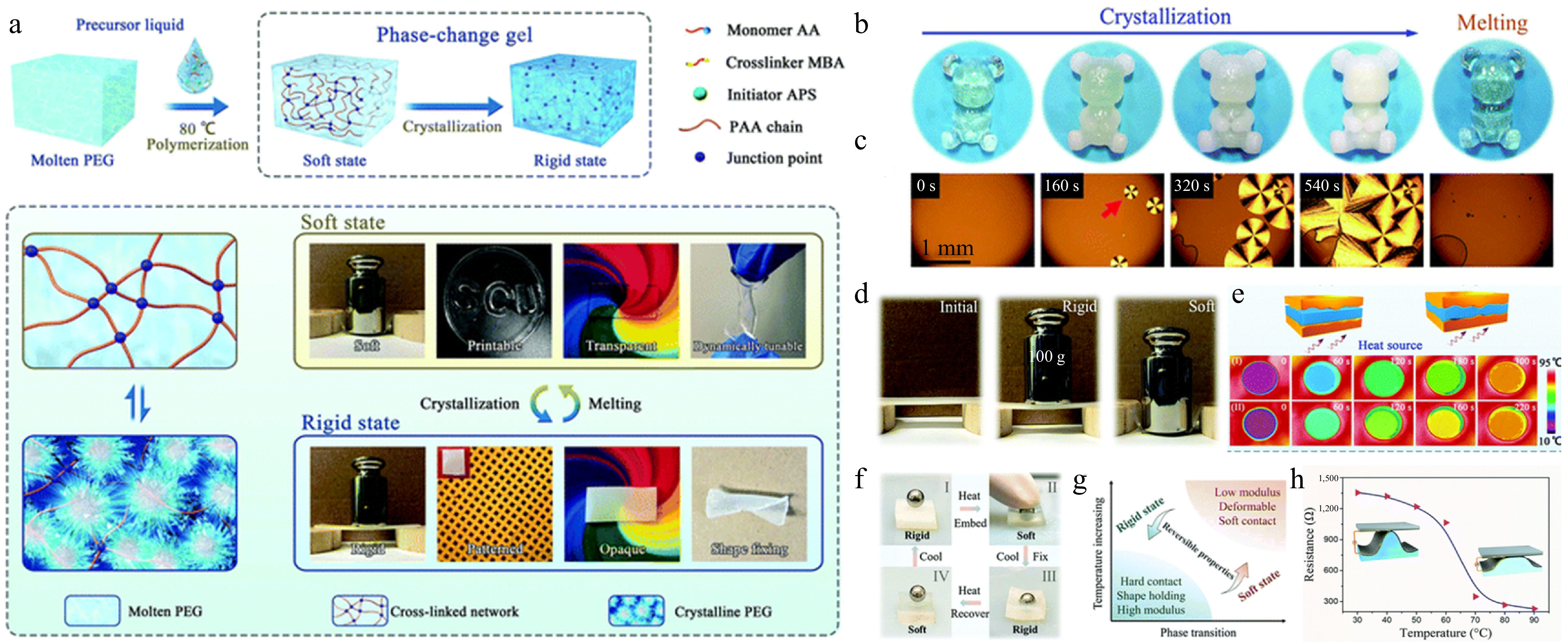
Figure 9.
(a) Preparation of phase change gels and their mechanical properties in soft and rigid states[22]. (b) Macroscopic and (c) microscopic images of the crystallization and re-melting process of the phase change gel[22]. (d) Digital images showing the stiffness difference for the phase change gel between the rigid and soft states[22]. (e) A comparison of heat conduction under two different states at 90 °C[22]. (f) Demonstration of the shape memory effect of the phase change gel[22]. (g) Schematic of the highly tunable and reversible features of the phase change gel[22]. (h) Electrical resistance change of the integrated circuit as a function of temperature[22].
-
-
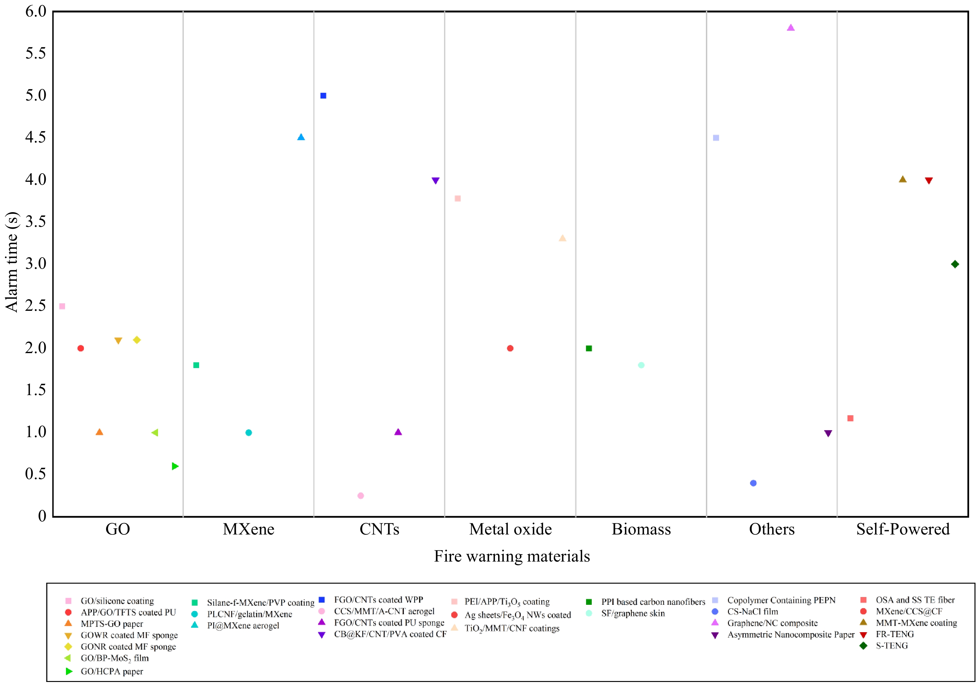
Figure 11.
Comparison of flame detection alarm time. Notes: GO/silicone coating[8]. APP/GO/TFTS coated PU[65]. MPTS-GO paper[66]. GOWR- coated MF sponge[67]. GONR coated MF sponge[67]. GO/BP-MoS2 film[31]. GO/HCPA paper[31]. Silane-f-MXene/PVP coating[33]. PLCNF/gelatin/MXene[49]. PI@MXene aerogel[68]. FGO/CNTs coated WPP[69]. CCS/MMT/A-CNT aerogel[37]. FGO/CNTs coated PU sponge[70]. CB@KF/CNT/PVA coated CF[19]. PEI/APP/Ti3O5 coating[43]. Ag sheets/Fe3O4 NWs coated[20]. TiO2/MMT/CNF coatings[71]. PPI-based carbon nanofibers[45]. SF/graphene skin[72]. Copolymer containing PEPN[62]. CS-NaCl film[73]. Graphene/NC composite[9]. Asymmetric Nanocomposite Paper[28]. OSA and SS TE fiber[50]. MXene/CCS@CF[51]. MMT-MXene coating[52]. FR-TENG[74]. S-TENG[75].
-
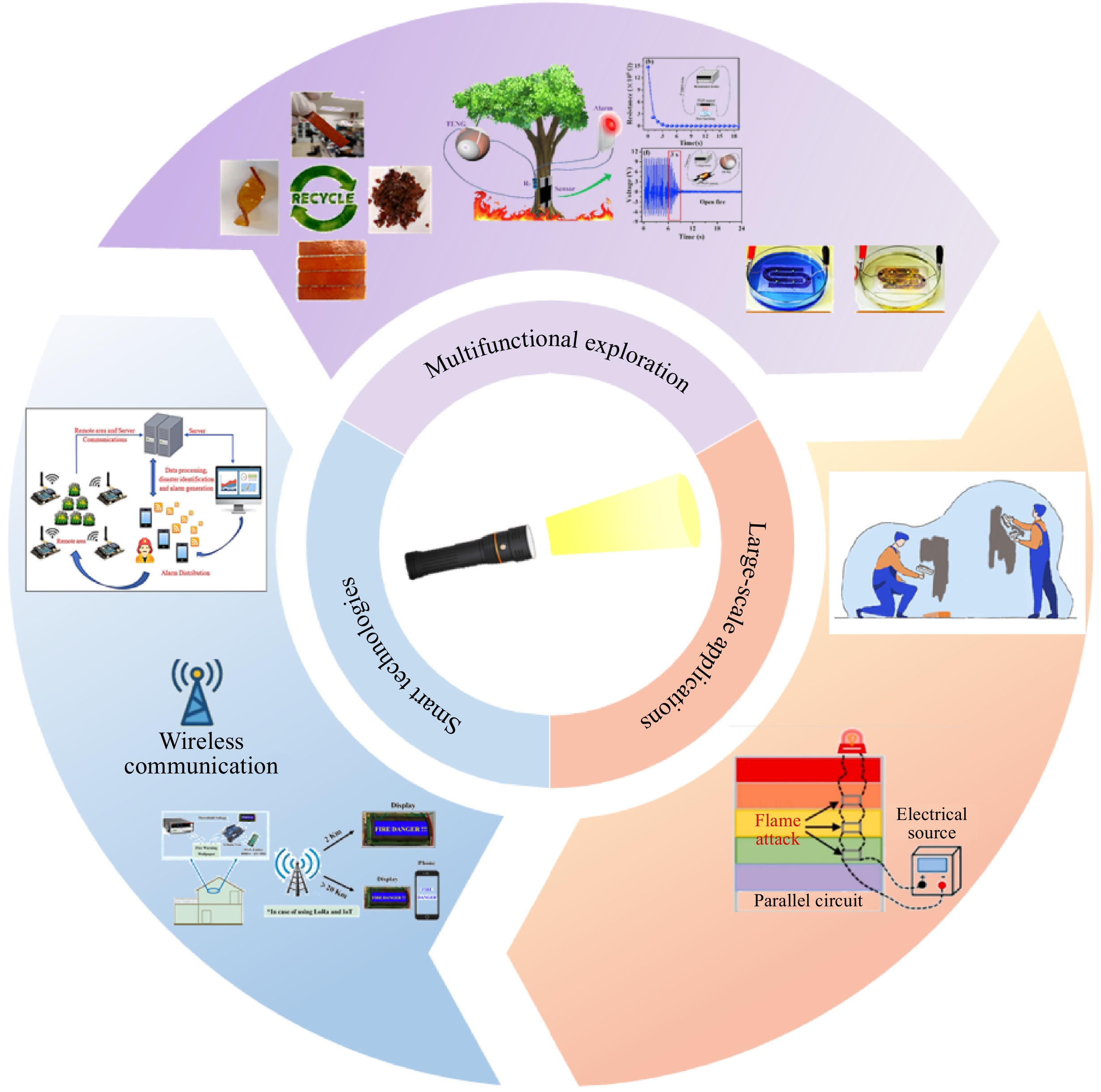
Figure 12.
Development prospects of fire-warning systems. Recyclability and processability of BRSC Schematic diagram of self-powered[76]. Forest fire- alarm system for spherical standalone TENG (S-TENG) as a wind energy collector[75]. Electrical stability test of the LED arrays under water and oil phase[77]. Wireless conversion diagram of fire signal to Wi-Fi signal for remote monitoring of fire-alarm process[78]. Remote area fire detection system based on Internet of Things[11]. Schematic diagram of multi-point flame cycle detection sensor circuit connection[71].
Figures
(12)
Tables
(0)