-
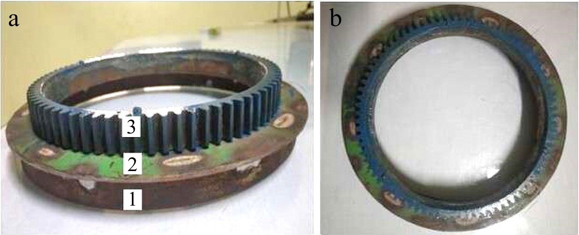
Figure 1.
(a) Front view of upper unit: 1. circular flat; 2. circular plate; 3. ring gear. (b) Top view of the upper unit.
-
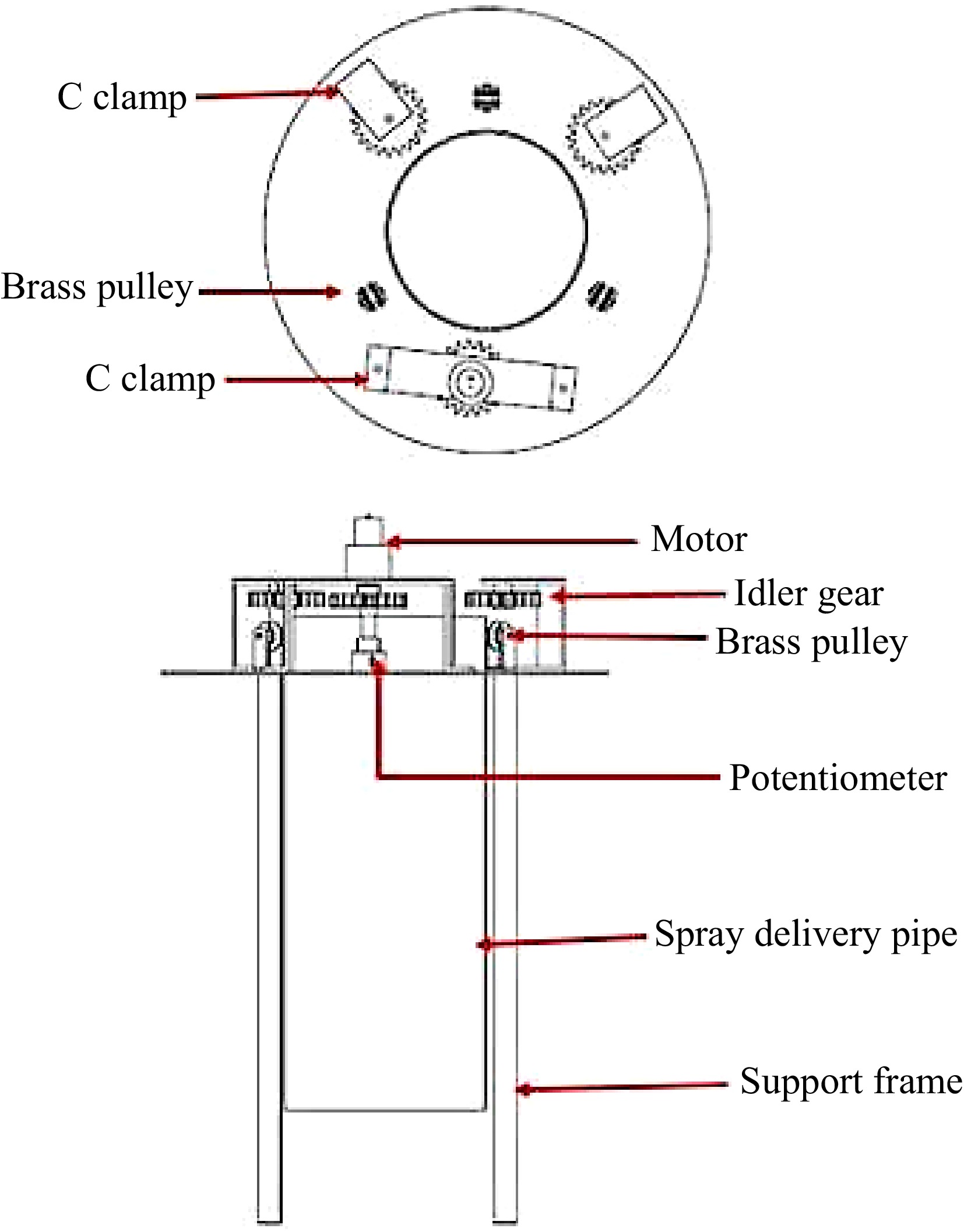
Figure 2.
Sketch of developed lower unit.
-
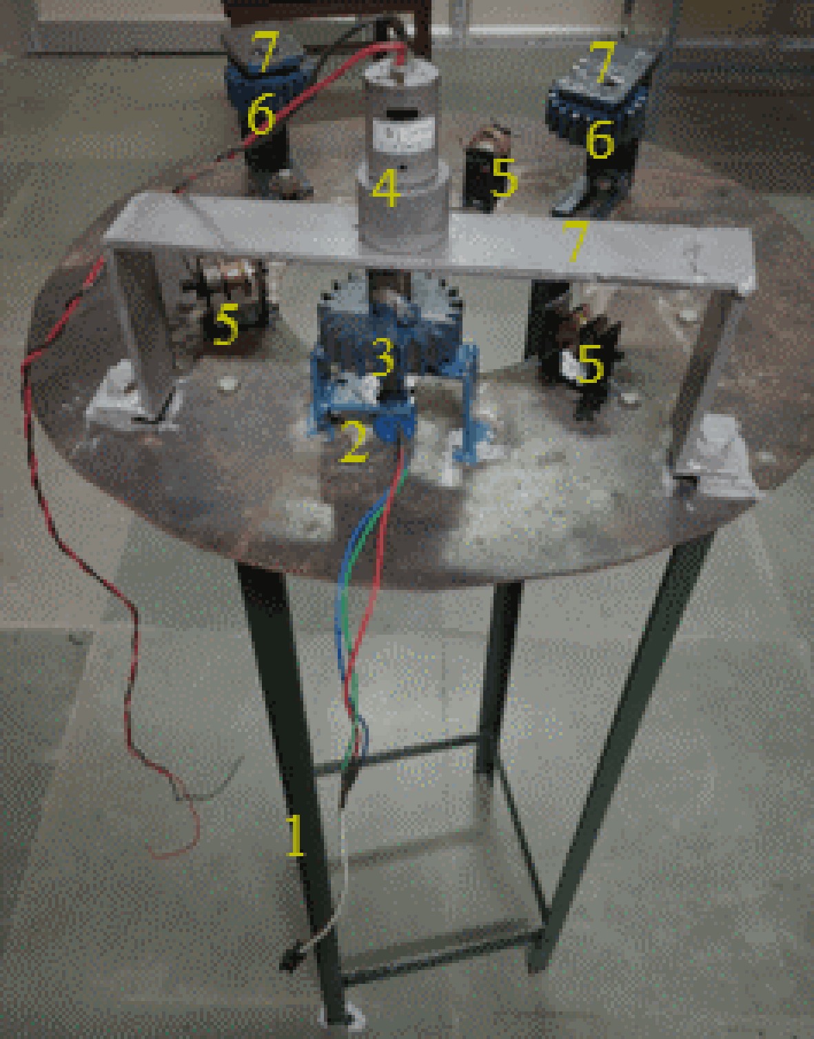
Figure 3.
Schematic view of lower unit: 1. four leg stand, 2. position sensor, 3. pinion gear, 4. motor, 5. brass pulley, 6. idler gear, 7. C clamp.
-
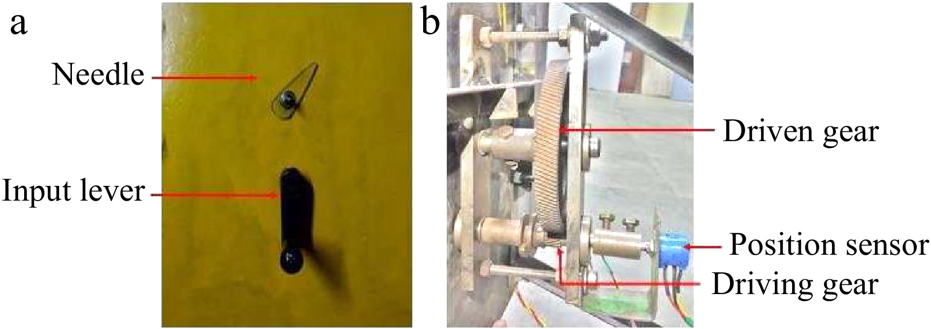
Figure 4.
Photograph of positioning and indicating unit.
-
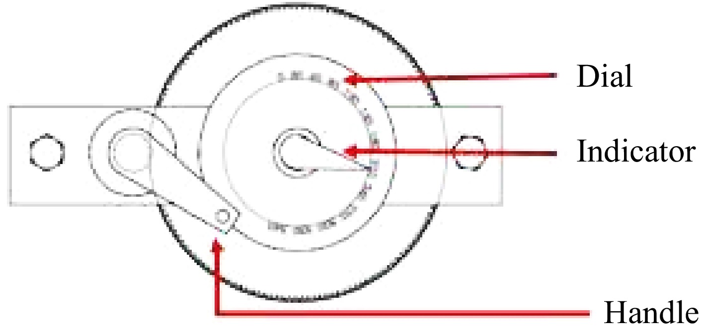
Figure 5.
Position indicator of spray delivery pipe.
-
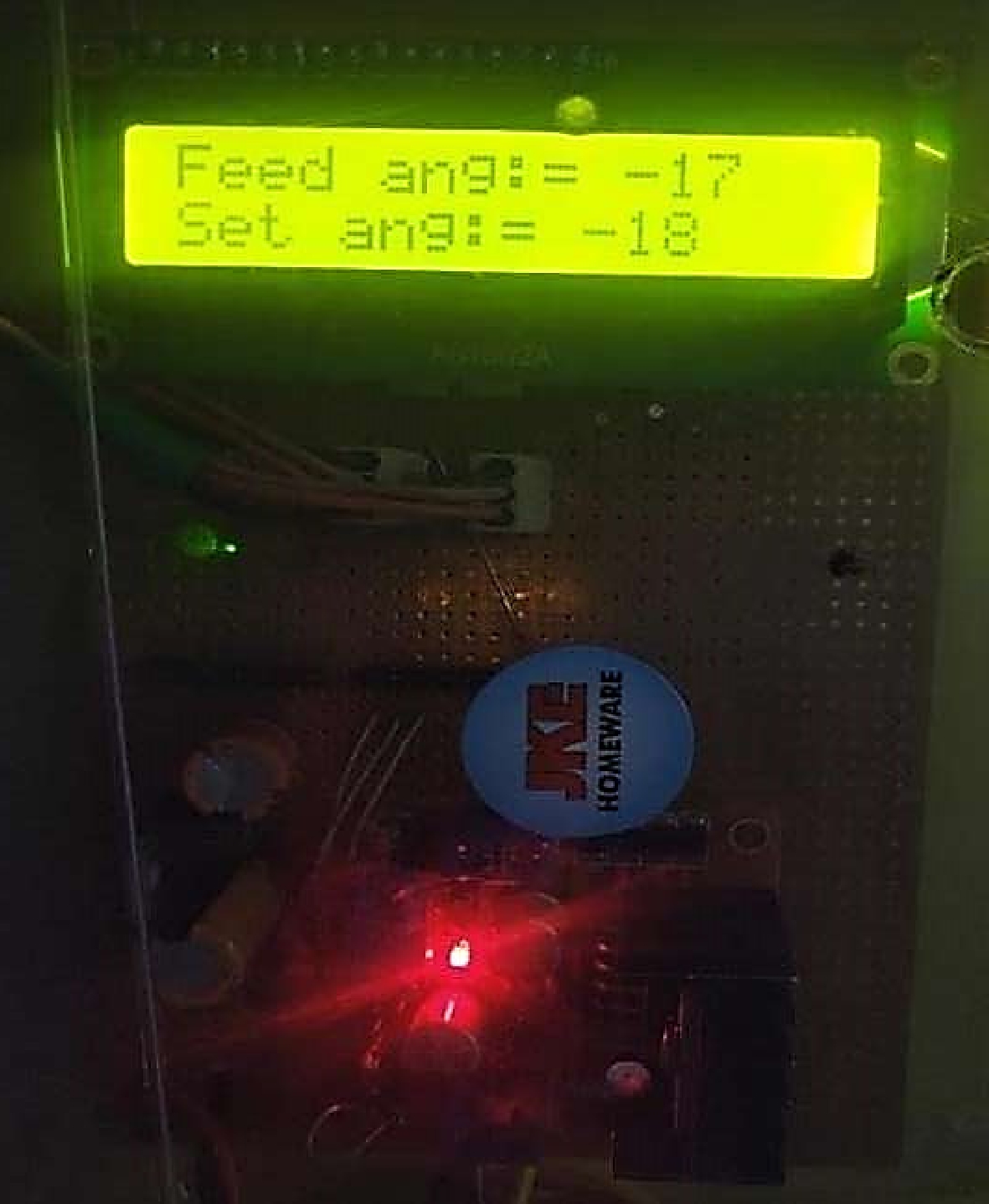
Figure 6.
Developed microcontroller-based embedded system.
-
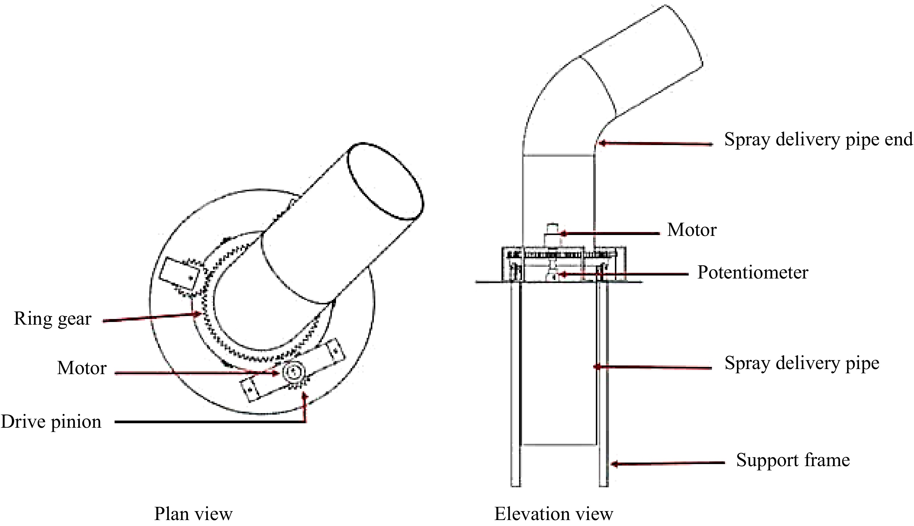
Figure 7.
Sketch of automatic control unit for spray delivery pipe.
-
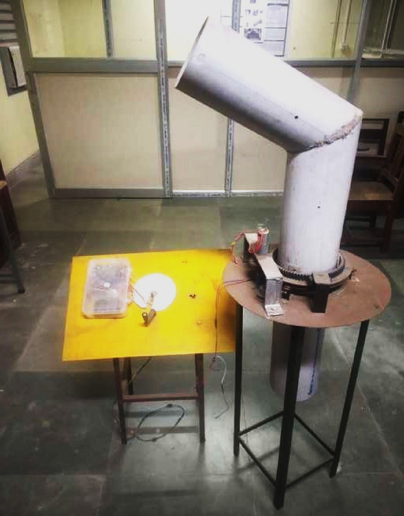
Figure 8.
Developed laboratory setup for the air blast sprayer.
-
Figure 9.
Schematic layout of the automatic spray pipe positioning and indicating system.
-
Figure 10.
Real-time position control of spray delivery pipe.
-
Figure 11.
Real-time response for every 30° rotation of spray delivery pipe.
-
Figure 12.
Comparison between set position and current position of delivery spray pipe.
Figures
(12)
Tables
(0)