-
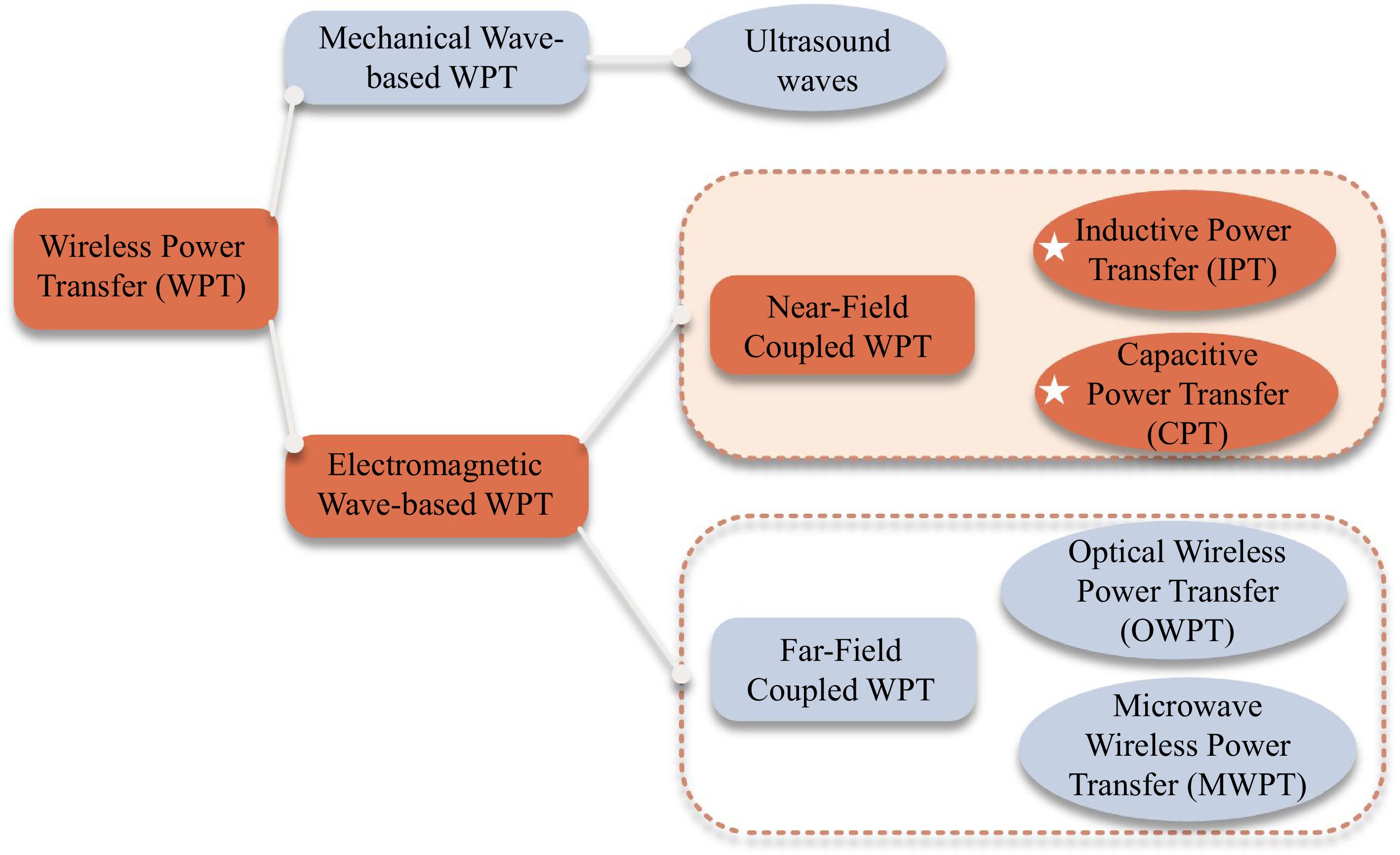
Figure 1.
Classification of WPT.
-
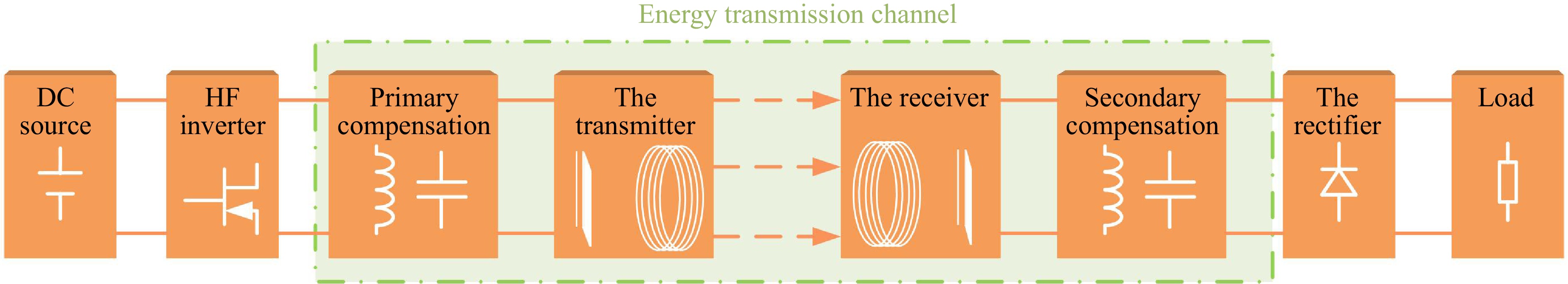
Figure 2.
Integral structure of the WPT system.
-
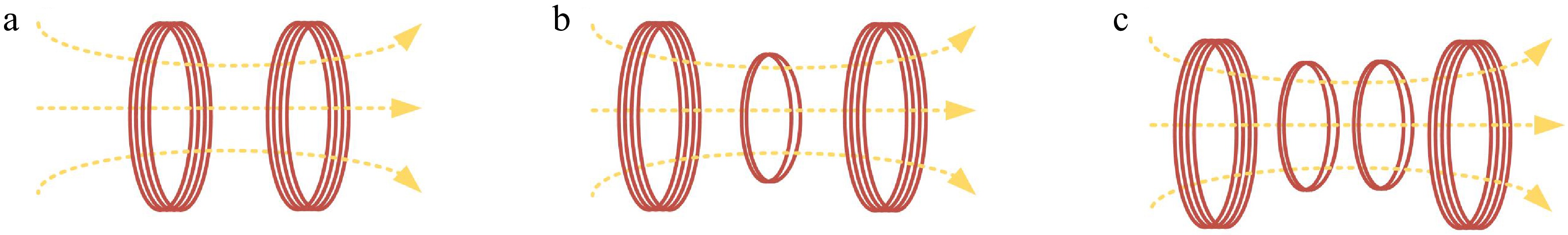
Figure 3.
Basic structures in the IPT system. (a) Two-coil. (b) Three-coil. (c) Four-coil.
-
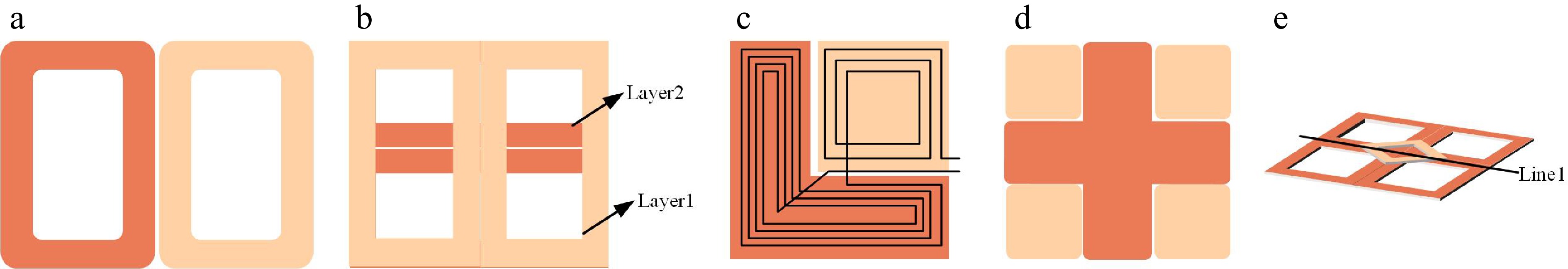
Figure 4.
Enhancing misalignment tolerance structures. (a) DD coil. (b) Double-layer DD coil. (c) LD coil. (d) Meter-type coil. (e) QDS coil.
-
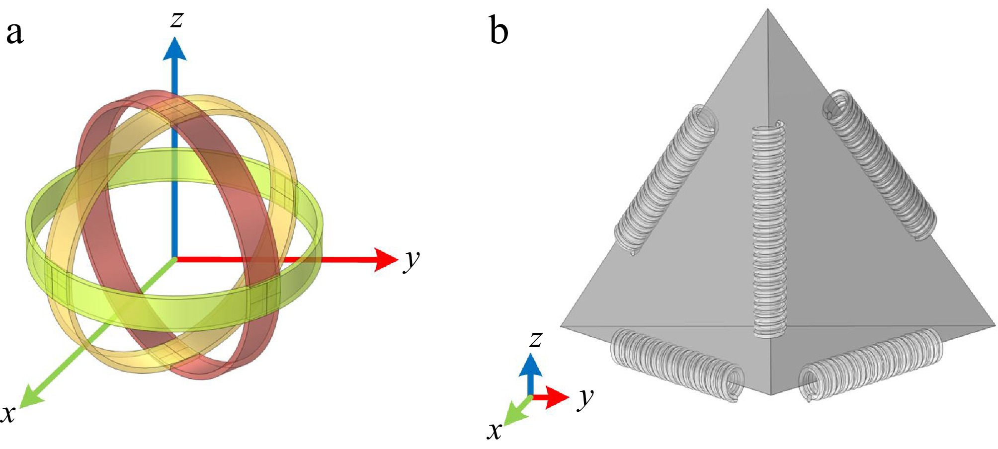
Figure 5.
Omnidirectional coupling coil structures. (a) Spherical coil. (b) Regular tetrahedron.
-
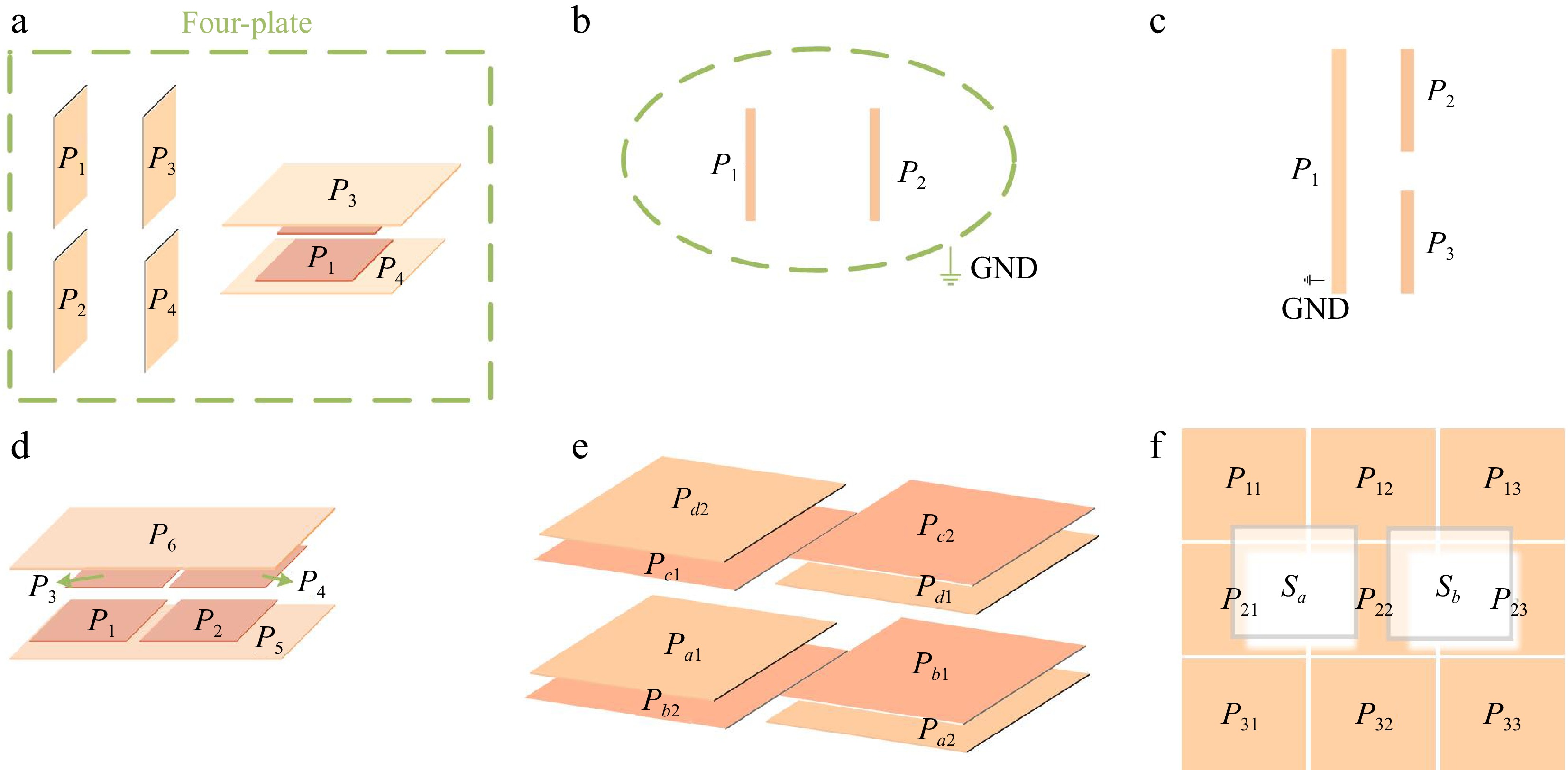
Figure 6.
The coupling structure researches of CPT systems. (a) Four-plate. (b) Two-plate. (c) Three-plate. (d) Six-plate. (e) Cross-coupling four-plate. (f) Matrix-type plate.
-
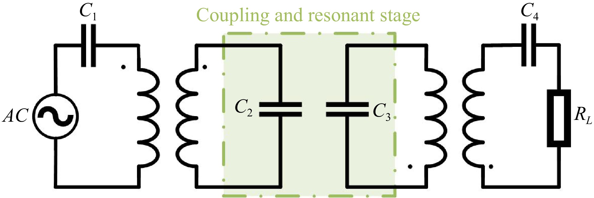
Figure 7.
A novel compensation incorporates coupling coils with mutual inductance.
-
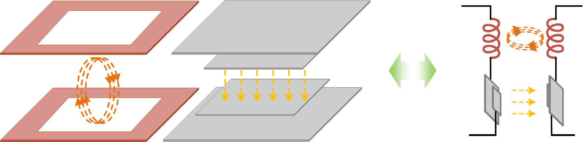
Figure 8.
Hybrid coupling structure with series configuration.
-
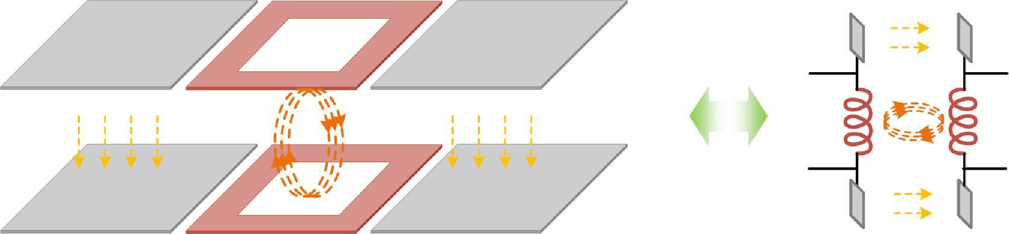
Figure 9.
Hybrid coupling structure with parallel configuration.
-
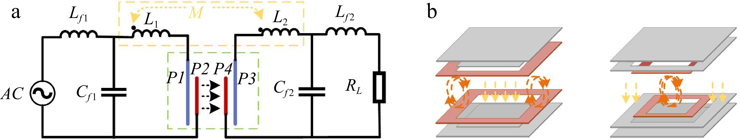
Figure 10.
Integrated coupling mechanism and shared compensation topology. (a) Shared compensation topology. (b) Coupling mechanisms.
-
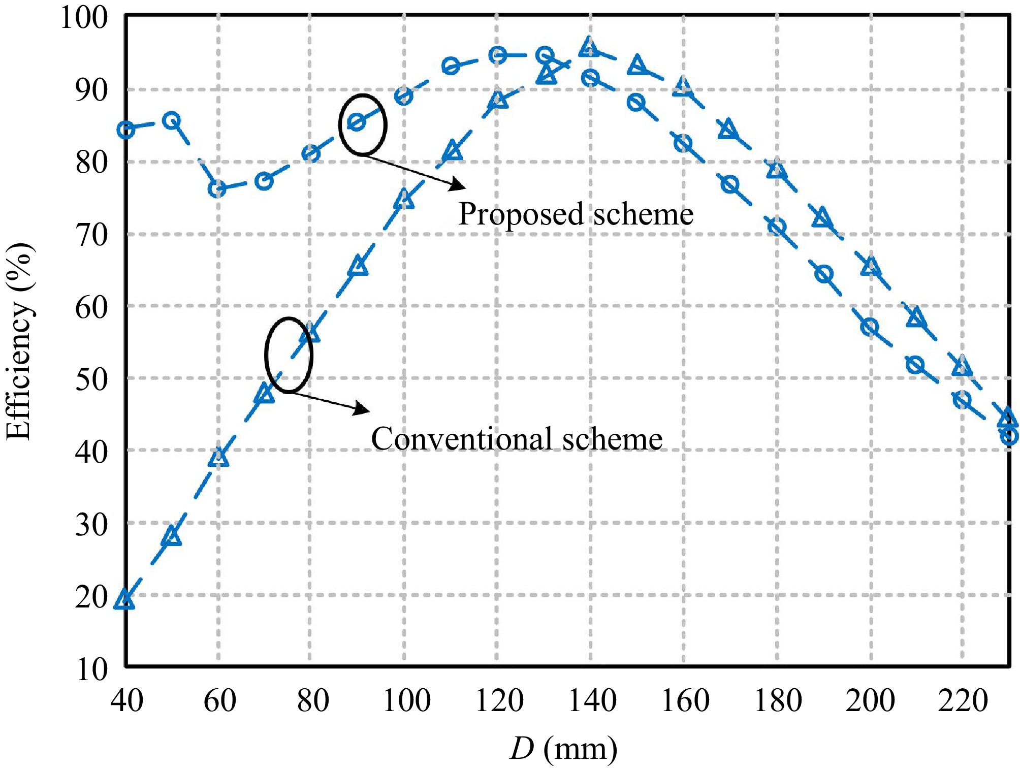
Figure 11.
The relationship between D and η between proposed systems[80].
-
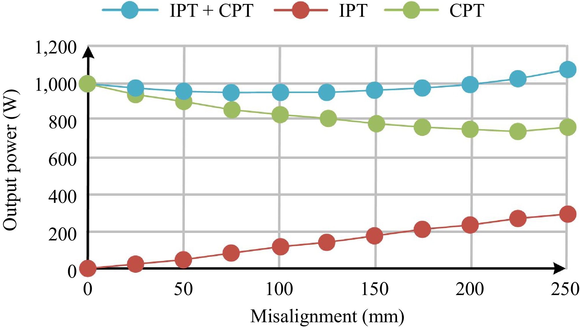
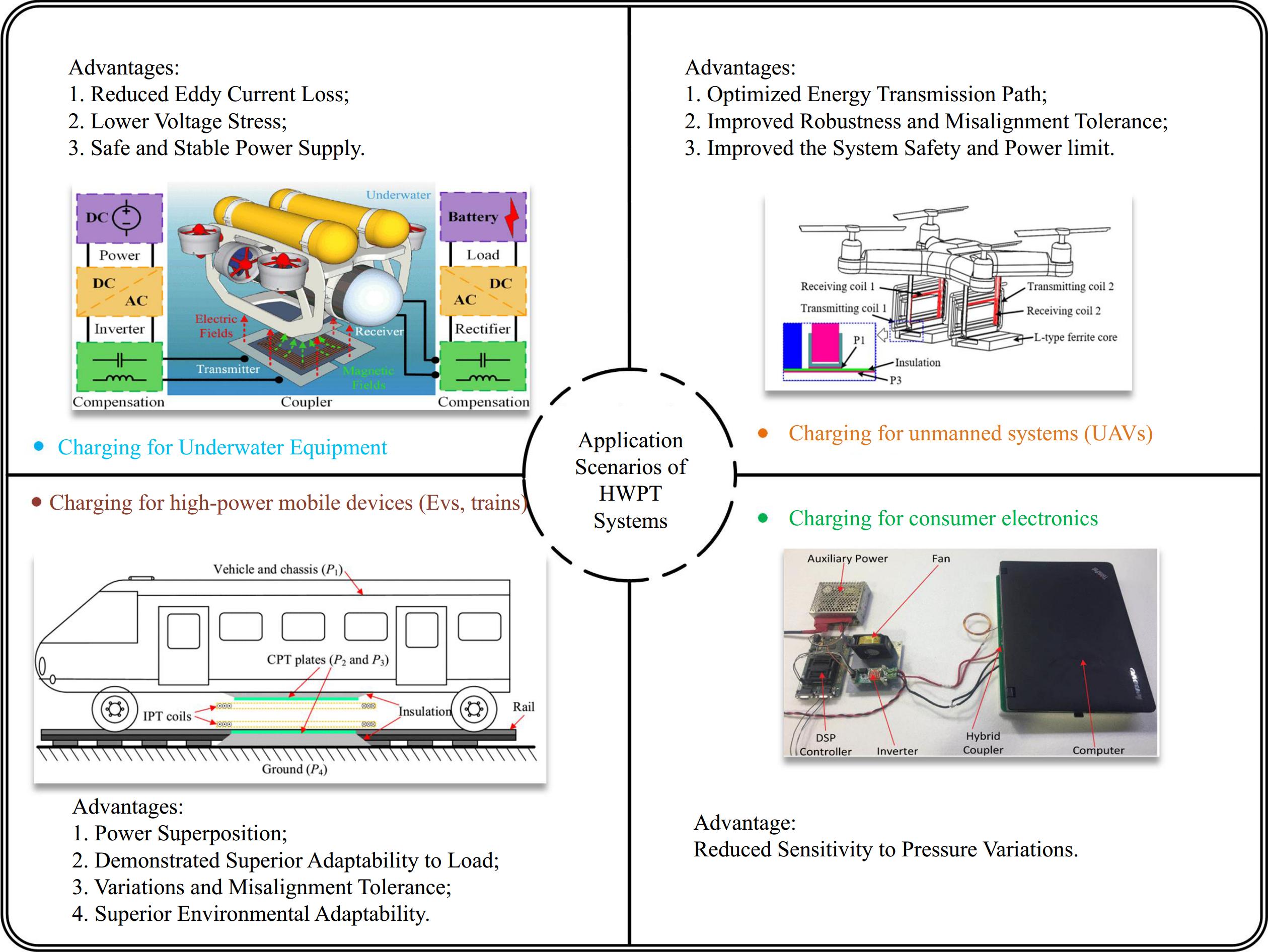
Figure 12.
The unique advantages of HWPT, enhanced tolerance to misalignment.
-
-
Compensation topologies Advantages Disadvantages Application scenarios Series-Series (SS) 1. Straightforward and readily implementable; 2. High transmission efficiency. Sensitive to load variations. Constant load. Series-Parallel (SP) Adaptable to load changes. High voltage required on the transmitter. Dynamic load and large load resistance. Parallel-Series (PS) Flexible adjustment of the receiver functions. Poorly adapted to load variations and high impact of parasitic impedance. Small to medium power transmission. Parallel-Parallel (PP) Highly adaptable. High reactive power loss and low efficiency and complex circuit design. Stable voltage output and small power transmission. LCL Impedance matching and misalignment tolerance. High requirements for matching coil parameters and load dependency. Multiple loads and dynamic wireless charging application. LCC 1. Adaptable to the load and higher misalignment tolerance[27];
2. Adjustable I/O gain.Sensitivity to parameter changes and a higher cost. Require high output voltage stability and large load variations[28]. Table 1.
Summary of compensation topologies of IPT.
-
Compensation topologies Characteristics Ref. Inductive compensation (single L) 1. High-level compensation inductance;
2. Suitable for low-power, high-frequency applications.[48,49] LC compensation Resonant frequency can be effectively adjusted, but poor at adjusting to changing loads. [50−52] Higher resonance compensation LCL Better adaptability to load variations and misalignment. [53] CLLC Optimized system performance with high robustness. [54] LCLC 1. Bilateral LCLC compensation provides higher efficiency and better dynamic response;
2. Capable of maintaining stable power transfer over a wide range of load variations and misalignment.[55] Table 2.
The existing compensation topologies of CPT.
-
Technical indicators IPT CPT HWPT Transmission channel Magnetic 
Electric 
Magnetic and Electric Fields 
Frequency At kHz (85 kHz is the most used) MHz Depend on the form of coupling
between IPT and CPT (kHz ~ MHz)Distance Well (Range from centimeters to meters) Poor (10−100 mm) Better Electromagnetic shielding effect Low (need external shielding) Medium High Ability to pass through obstacles Low Medium High Others Easy to cause Eddy current problems Electric field leakage problem 1. Complementary functions of IPT and CPT;
2. Suppression of Frequency Splitting;
3. Misalignment Tolerance is increasedTable 3.
Analysis of IPT, CPT, and HWPT systems.
Figures
(13)
Tables
(3)