-
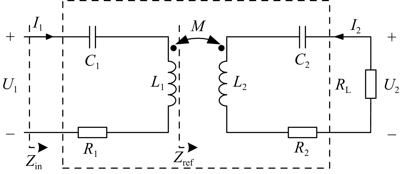
Figure 1.
Topology of S/S compensated WPT system.
-
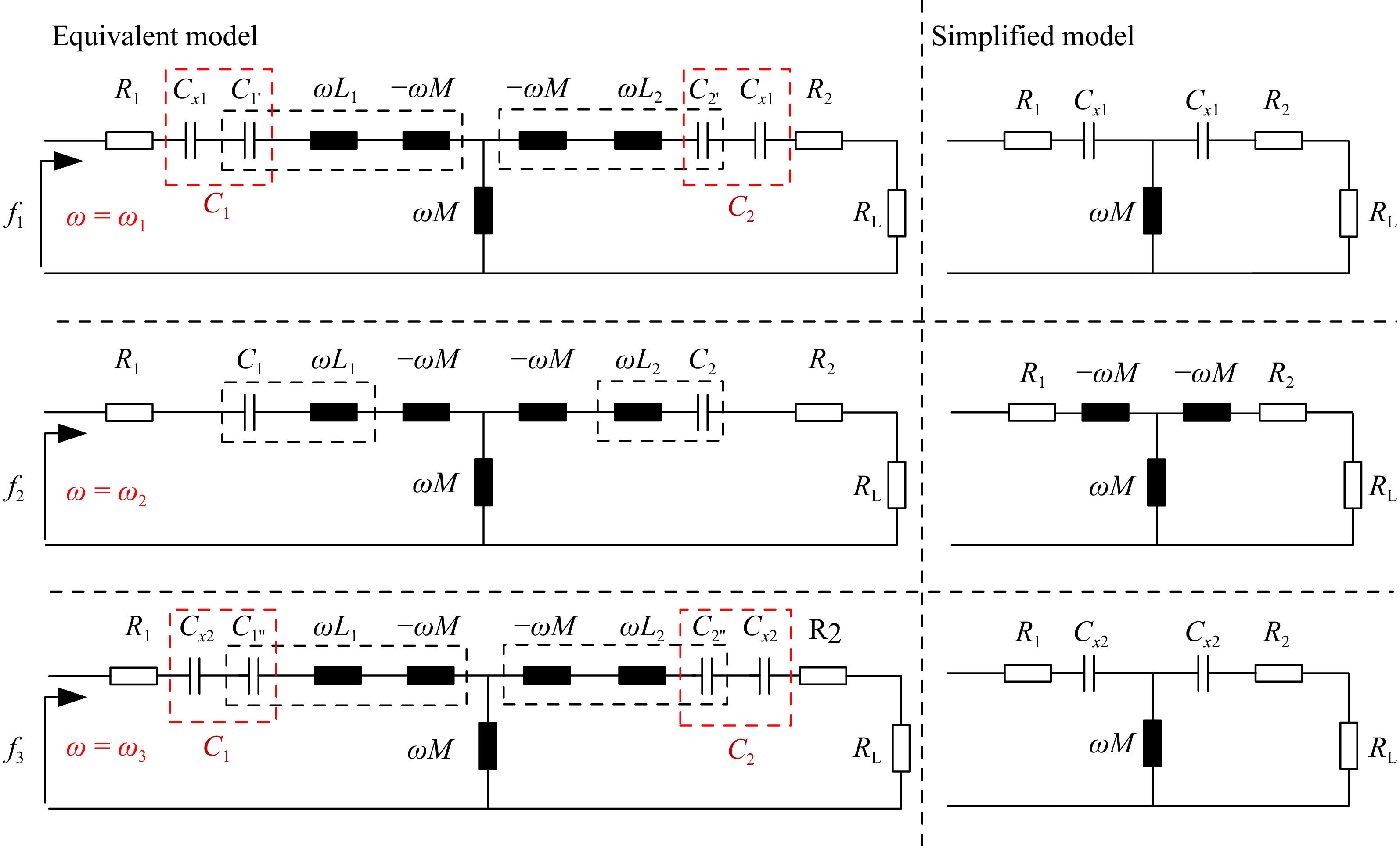
Figure 2.
T-equivalent model and the simplified model when Im(Zin) = 0.
-
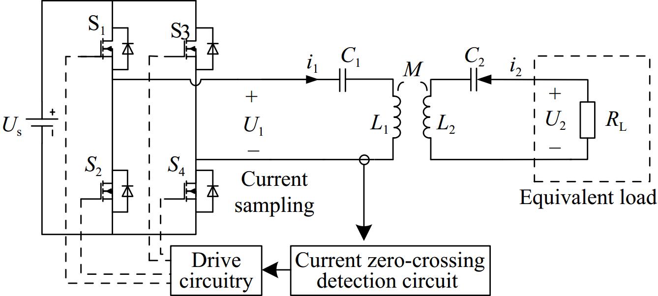
Figure 3.
Circuit implementation.
-
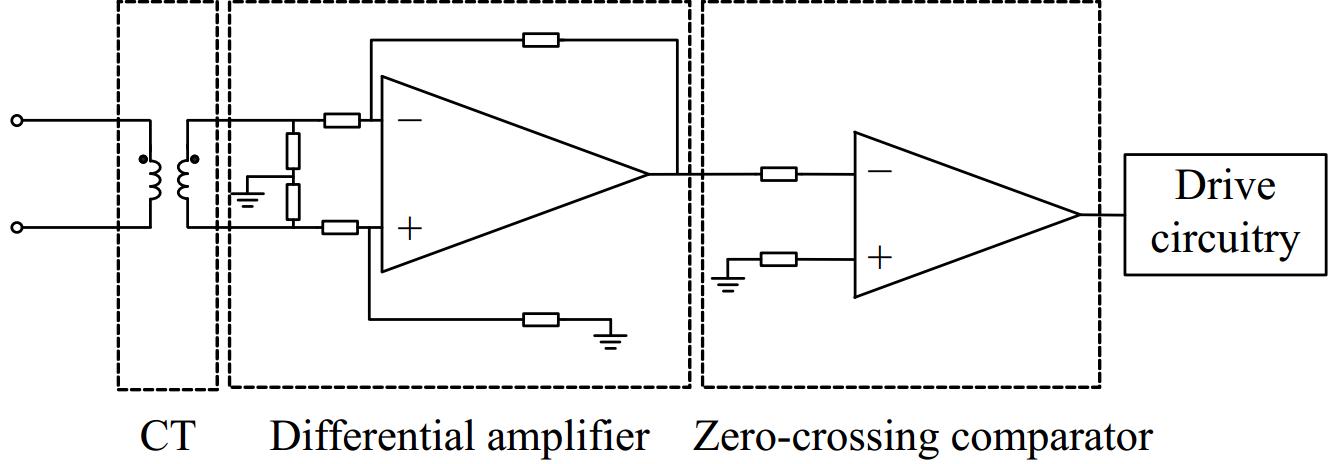
Figure 4.
Controller structure.
-
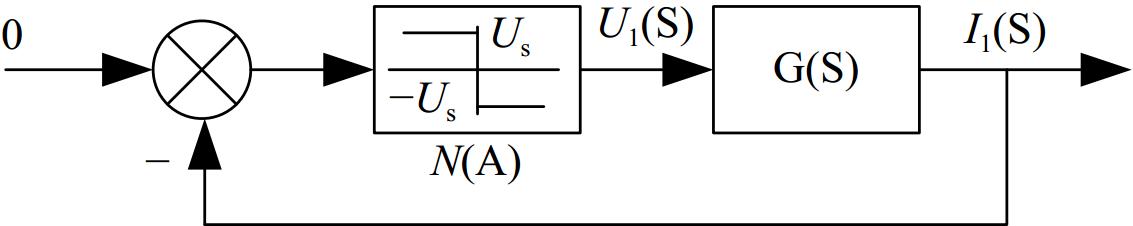
Figure 5.
Structure diagram of the system.
-
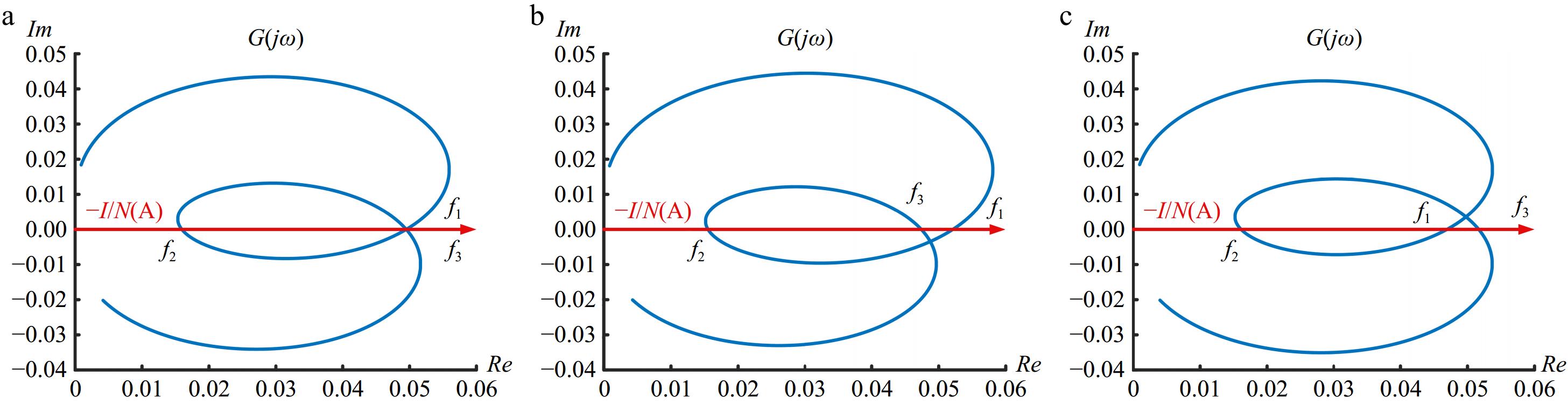
Figure 6.
Polar coordinate diagram. (a) ωp = ωs, (b) ωp < ωs, and (c) ωp > ωs.
-
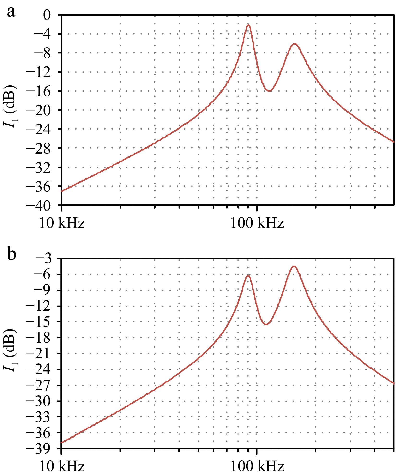
Figure 7.
Current amplitude frequency characteristics. (a) ωp < ωs, (b) ωp > ωs.
-
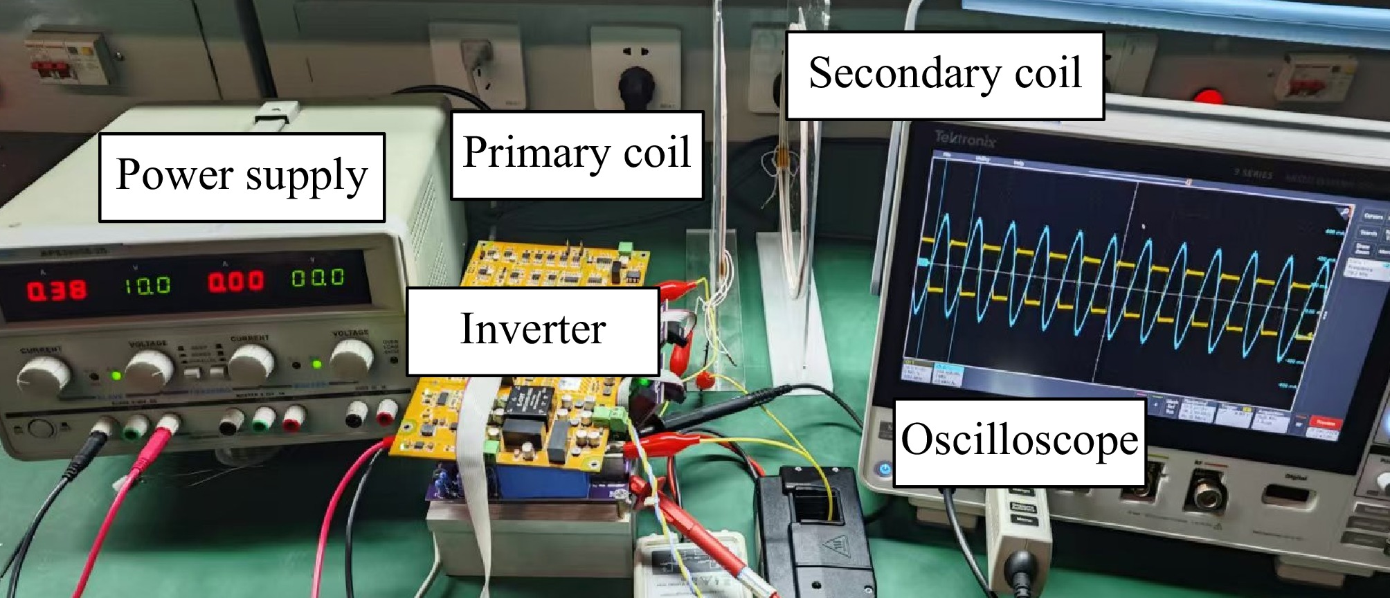
Figure 8.
Experimental device.
-
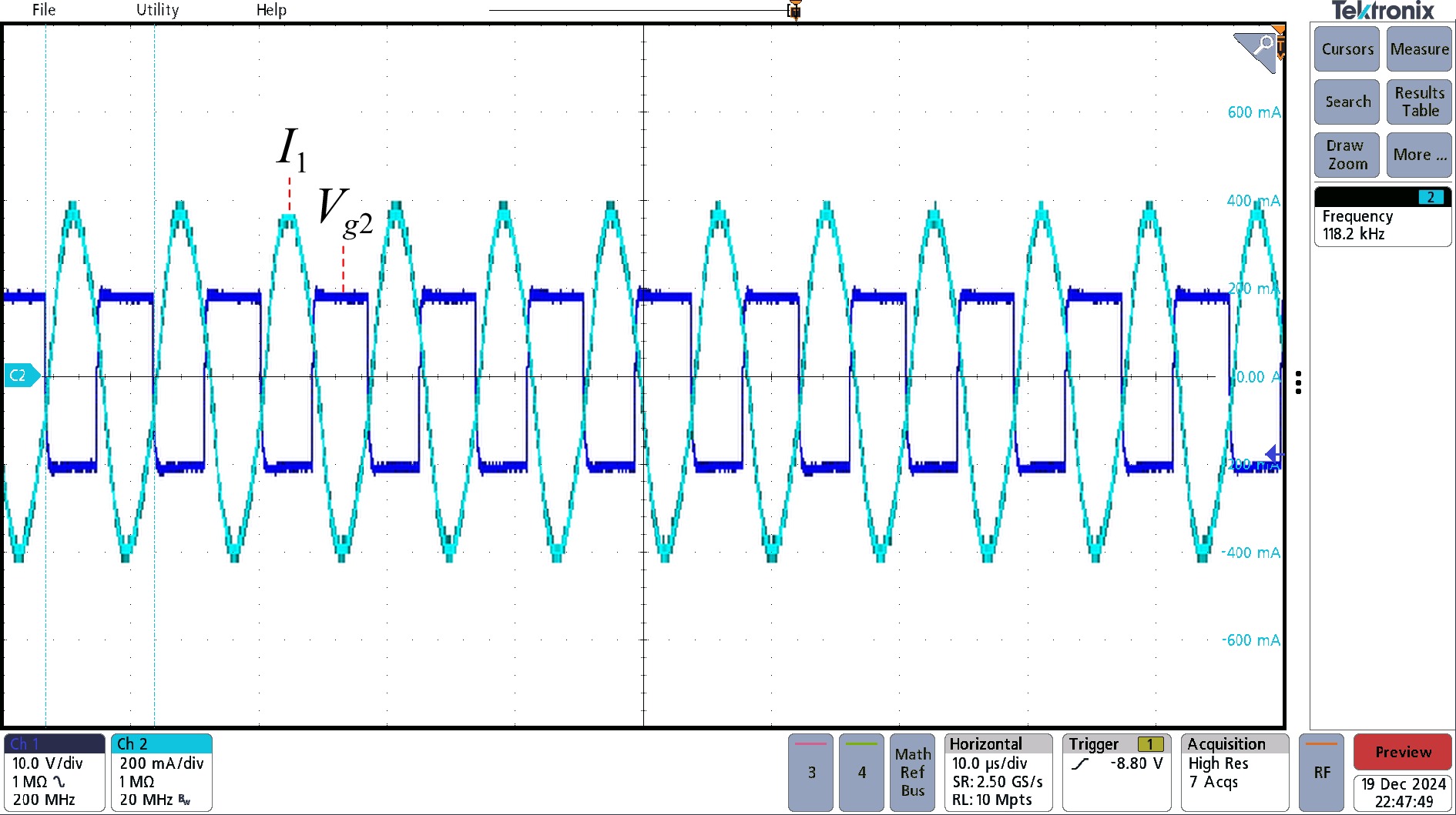
Figure 9.
Oscilloscope waveform.
-
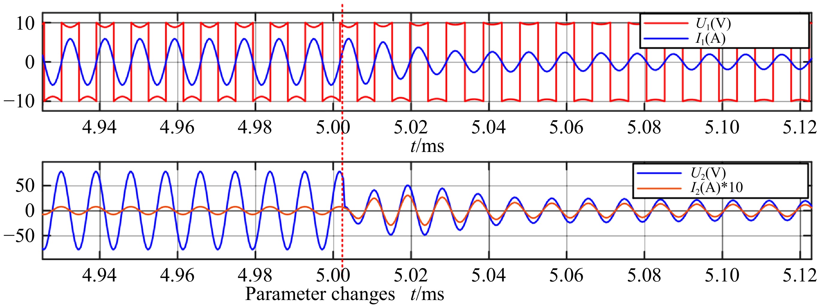
Figure 10.
Input and output waveforms during parameter changes.
-
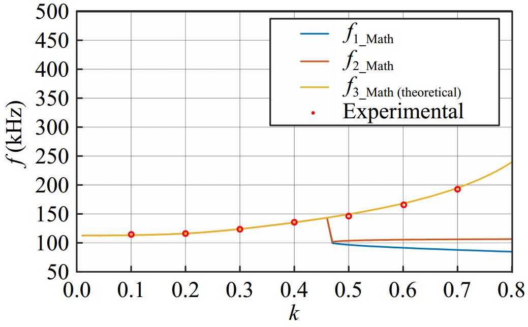
Figure 11.
Relationship between system operating frequency and coupling coefficient when ωp < ωs.
-
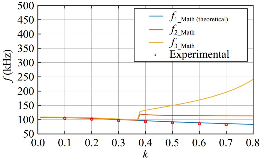
Figure 12.
Relationship between system operating frequency and coupling coefficient when ωp > ωs.
-
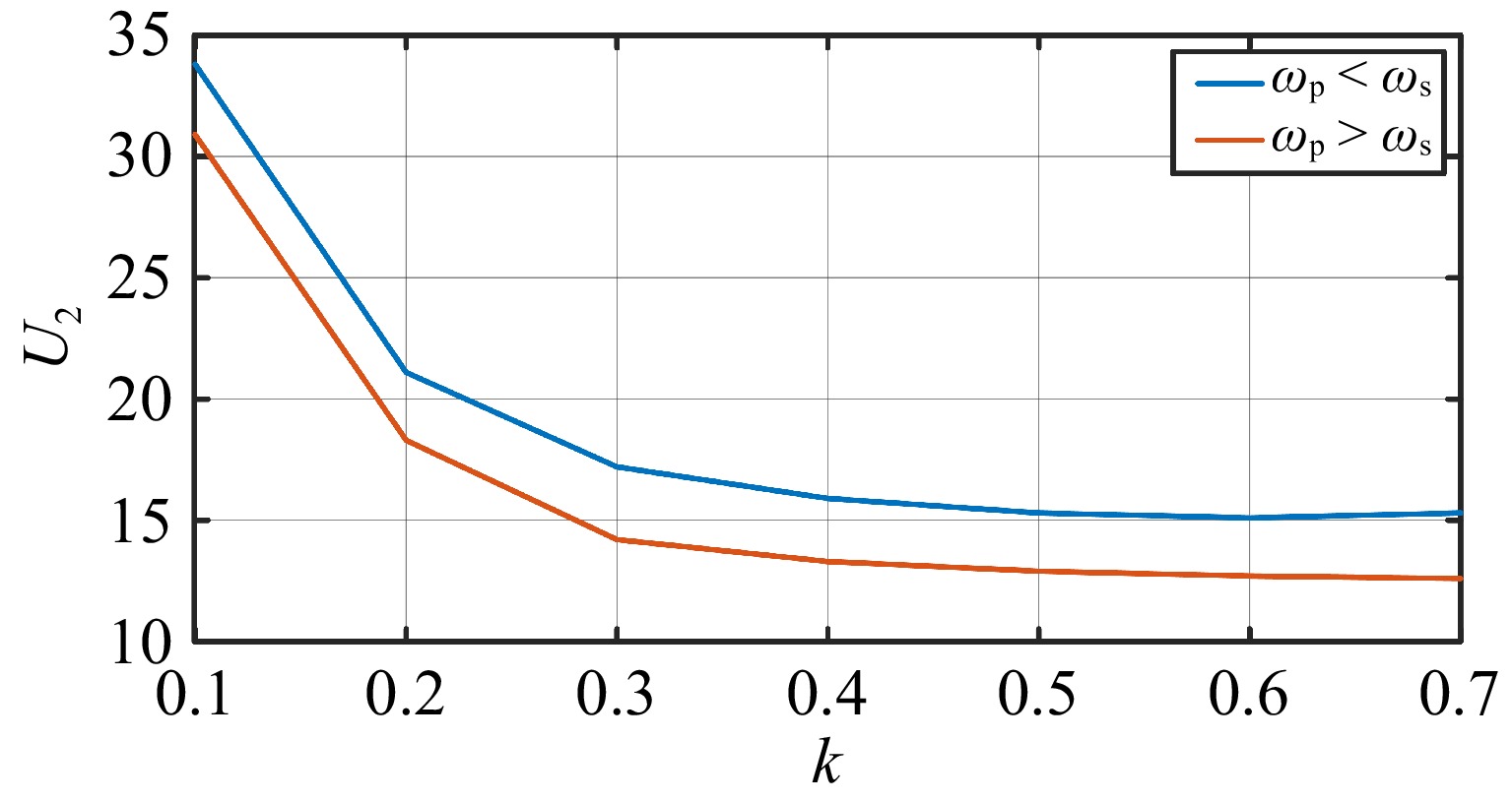
Figure 13.
Output voltage amplitude.
-
Parameters Value Input voltage Us 10 V Primary side compensation capacitor C1 20.1 (22.2) nF Primary coil self-inductive L1 103.2 μH Secondary coil self-inductance L2 103.4 μH Secondary side compensation capacitor C2 20.0 (22.1) nF Equivalent load RL 20 Ω Table 1.
System parameters.
Figures
(13)
Tables
(1)