-
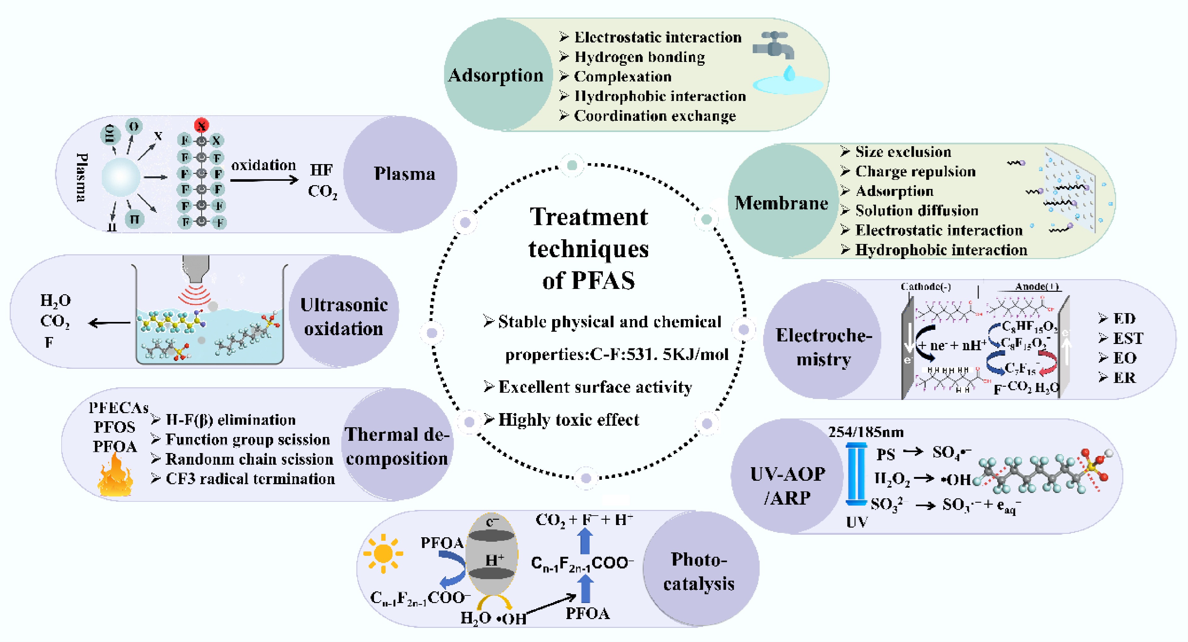
Figure 1.
Physical (green), and chemical (purple) technology principles for treating PFAS wastewater.
-
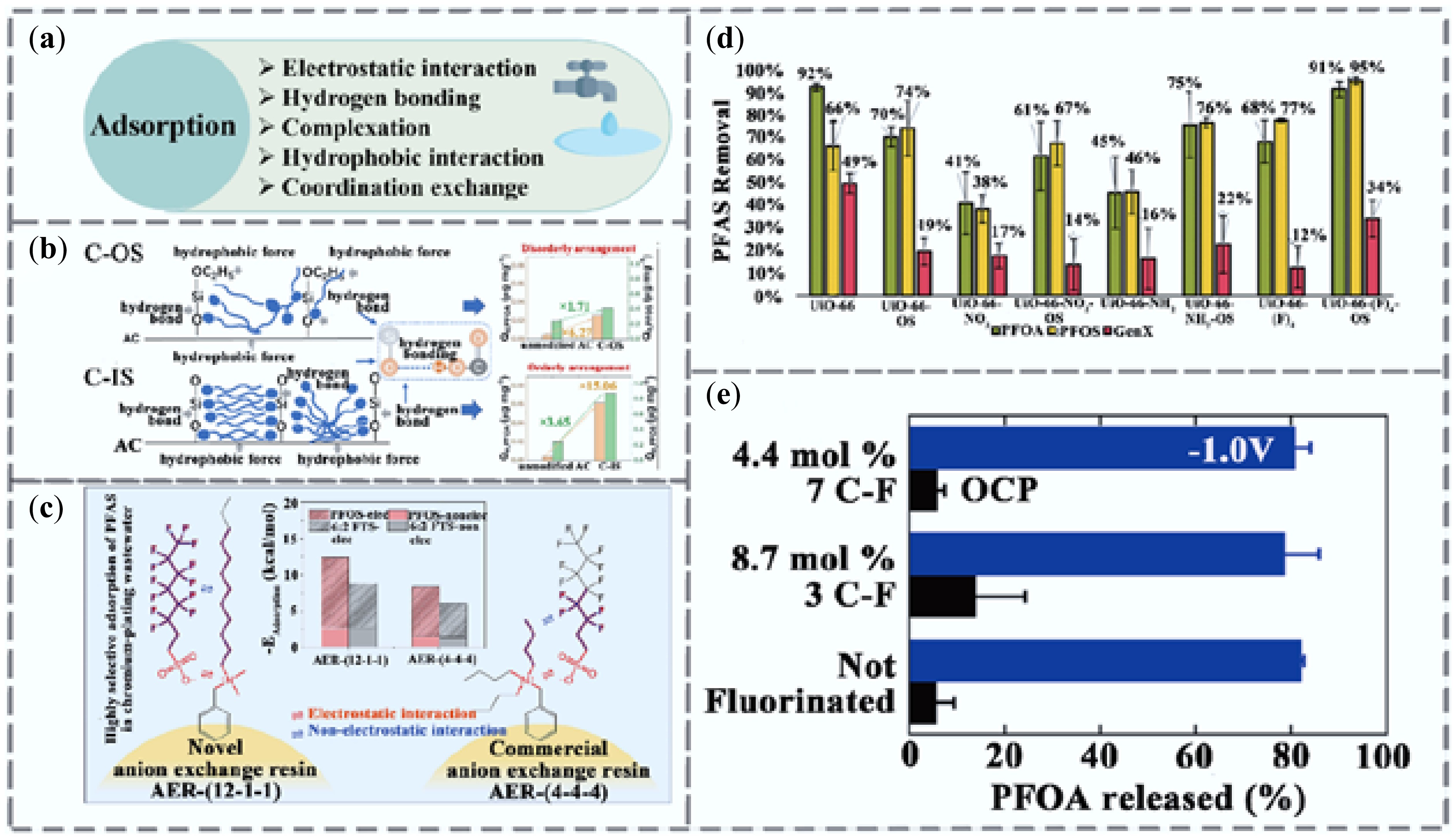
Figure 2.
Research progress on adsorption technologies for PFAS removal. (a) Adsorption removal mechanism. (b) Removal of PFAS using organosilicon (C-OS) and inorganic silicon (C-IS) modified activated carbon[33]. (c) Adsorption of PFAS by AERs with different quaternary ammonium functional groups and pore structures[34]. (d) Adsorption performance of UiO-66 MOFs for PFOA, PFOS, and GenX[35]. (e) Open circuit potential (OCP) of PFOA after 1-h adsorption at −1 V vs Ag/AgCl or at 1 V. Error bars represent standard deviations (n = 3)[36].
-
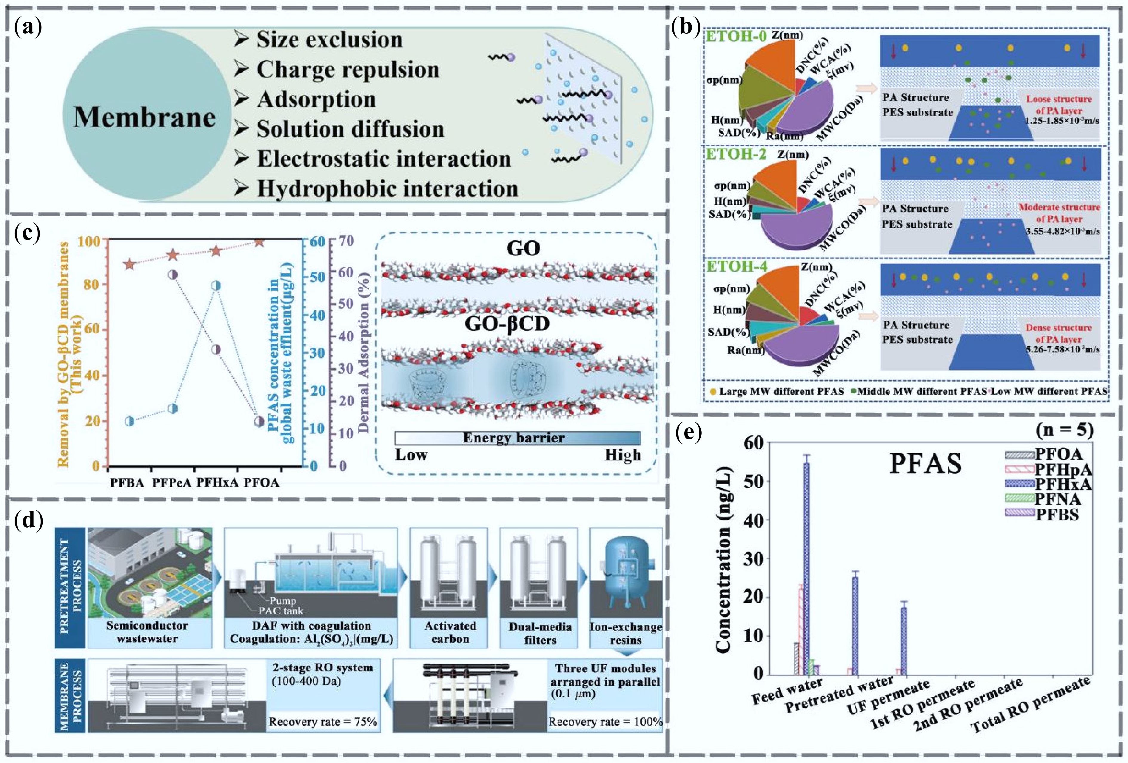
Figure 3.
Research progress on membrane separation technology for PFAS removal. (a) Membrane separation removal mechanism. (b) PFAS removal mechanism of ETOH-regulated NF membranes[49]. (c) Retention of PFAS by GO-βCD composite membranes[50]. (d) Trends in the removal of PFAS from semiconductor wastewater reuse systems on a pilot scale (n = 3)[51]. (e) Schematic diagram of pilot-scale semiconductor wastewater reuse system composed of DAF, activated carbon, ion exchange resin, dual-media filter, UF and two-stage reverse osmosis membrane[51].
-
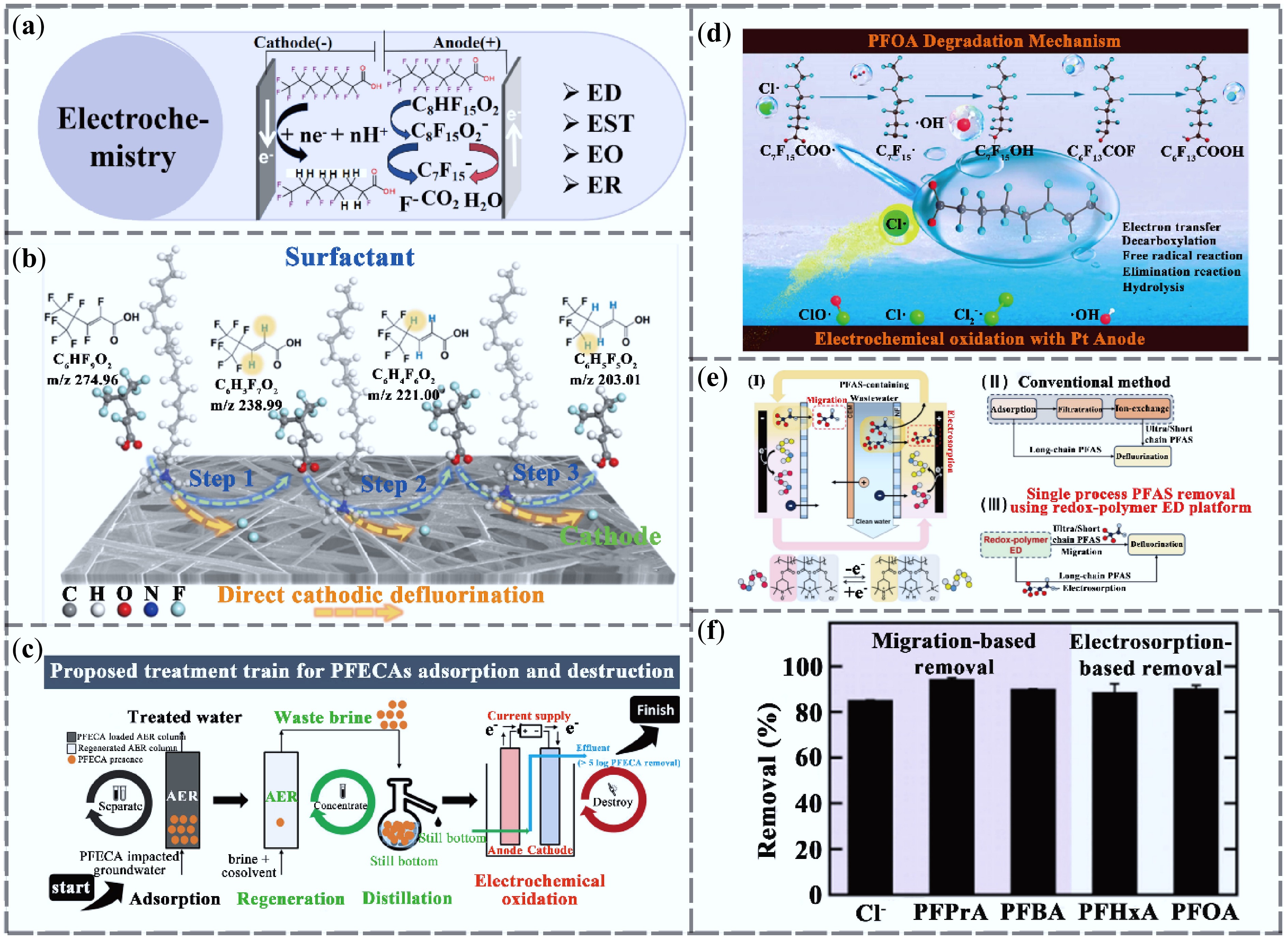
Figure 4.
Research progress in electrochemical technologies for PFAS removal. (a) Electrochemical removal mechanism. (b) Electroreduction system with quaternary ammonium surfactant-modified cathode for the degradation of unsaturated PFAS[60]. (c) Combined AER and EO process for removal and degradation of four structurally different perfluoroalkyl ether carboxylic acid (PFECA) compounds[61]. (d) Study on PFOA degradation in an EO system triggered by Cl• radicals[62]. (e) Electrodialysis system for removal of PFAS from oxidized polymers and mechanism diagram[63]. (f) Removal efficiencies of PFAS with different carbon chain lengths by the redox polymer electrodialysis system[63].
-
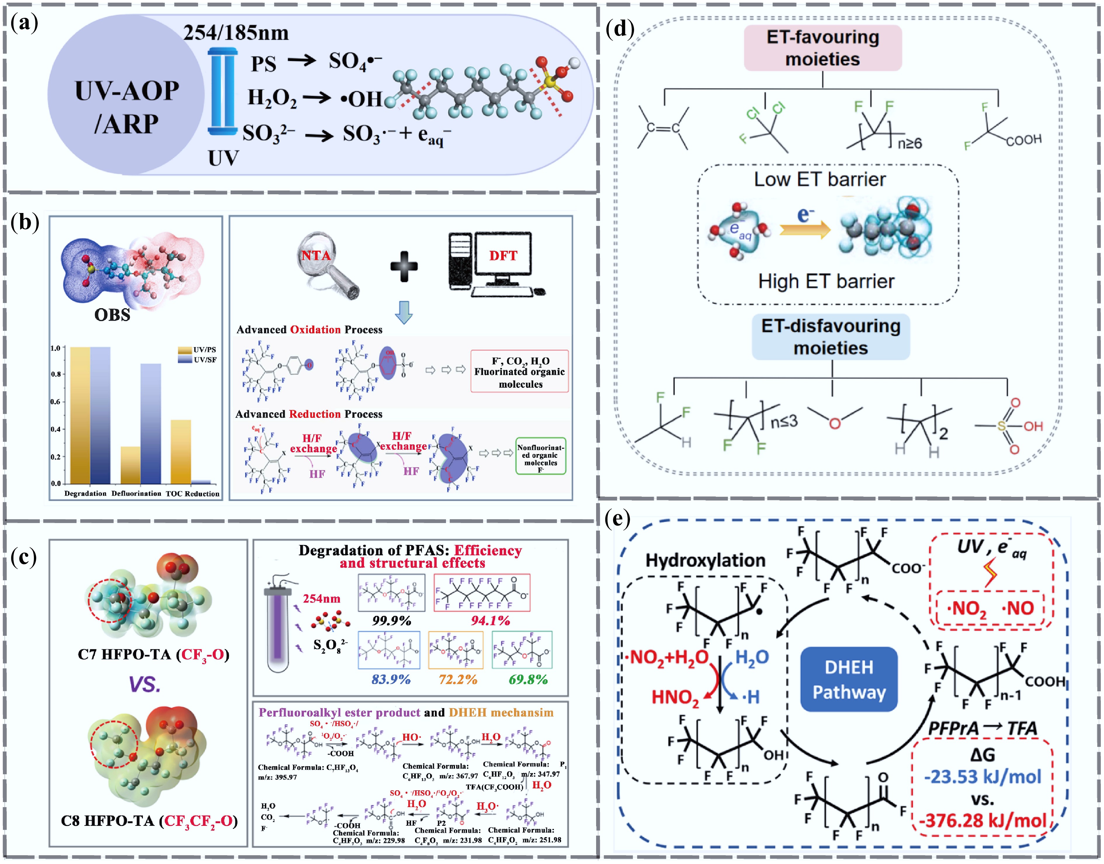
Figure 5.
Research progress of ultraviolet advanced oxidation and reduction technologies for PFAS removal. (a) UV-AOP/ARP removal mechanism. (b) Mechanisms of OBS degradation by UV/PS and UV/SF processes, along with degradation, defluorination, and TOC reduction after 10 h treatment of OBS-based fluorescent protein foam[72]. (c) Mechanism of C7 HFPO-TA degradation in the UV/PS system and the effect of carbon chain length on degradation efficiency[73]. (d) Functional groups promoting ET shown in pink regions, and those inhibiting ET shown in blue regions[74]. (e) DHEH pathway of nitrate-assisted PFAS degradation in the UV/S system[75].
-
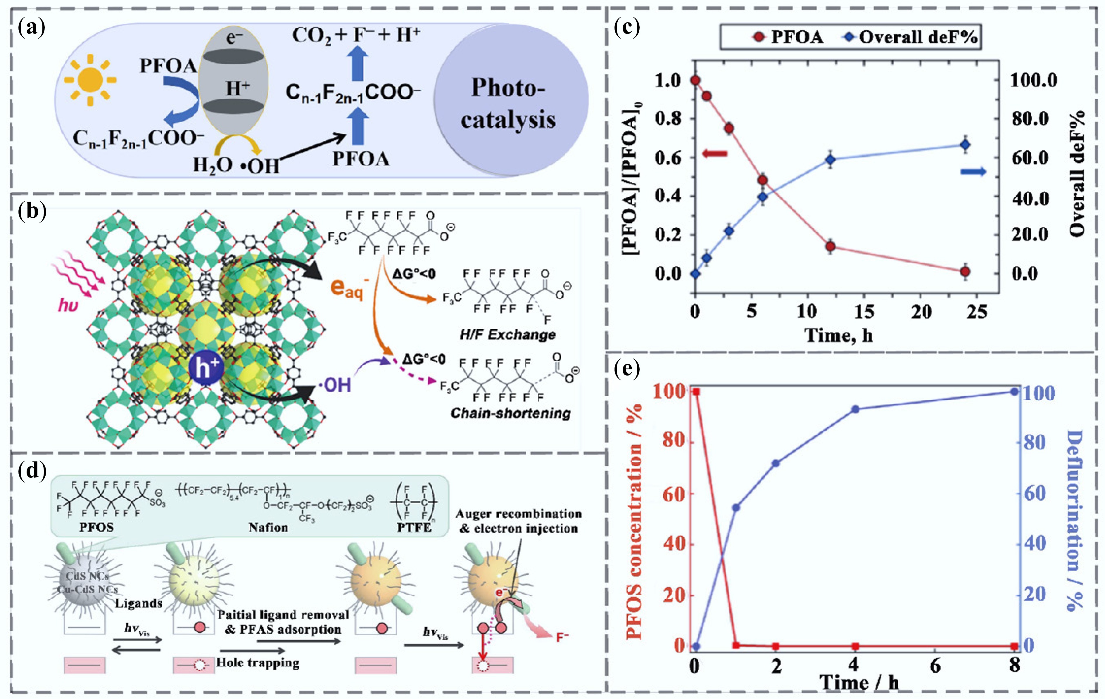
Figure 6.
Research progress on PFAS removal by photocatalytic technology. (a) Photocatalytic removal mechanism. (b) eaq−-dominated reductive defluorination of PFOA using Ti-based MOF materials[79]. (c) degradation of PFOA under irradiation and corresponding defluorination rate[79]. (d) reaction mechanism of PFAS defluorination by CdS under visible light[80]. (e) Concentration of PFOS in the reaction solution and its defluorination rate[80].
-
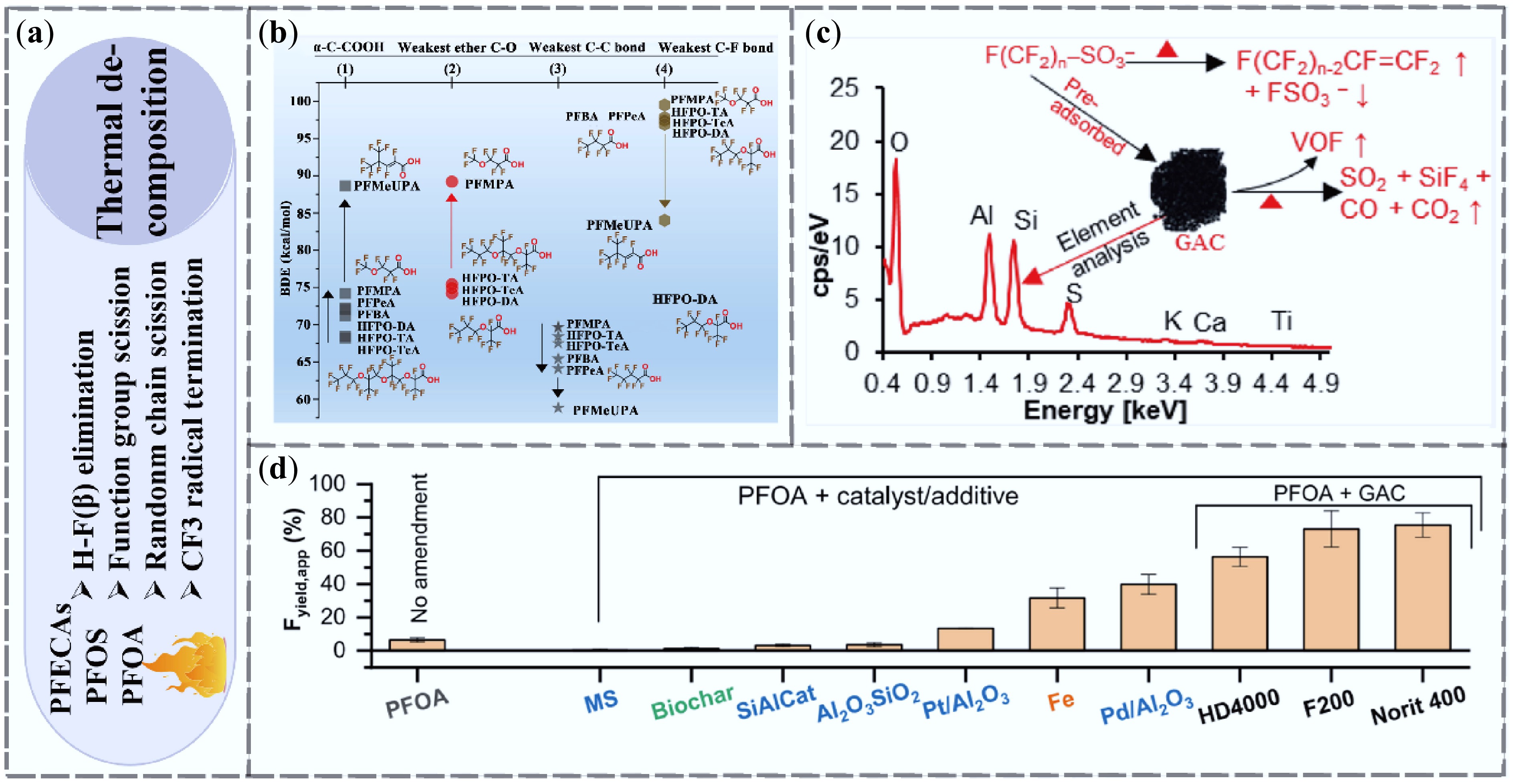
Figure 7.
Research progress on PFAS removal by thermal decomposition technologies. (a) Mechanism of thermal decomposition removal. (b) Thermal decomposition mechanisms of perfluoroalkyl ether carboxylic acids (PFECAs) and short-chain perfluoroalkyl carboxylic acids (PFCAs) based on functional group bond dissociation energies[89]. (c) Mechanism by which activated carbon promotes PFAS decomposition[90]. (d) Defluorination efficiency of supported and other catalysts for PFOA[91].
-
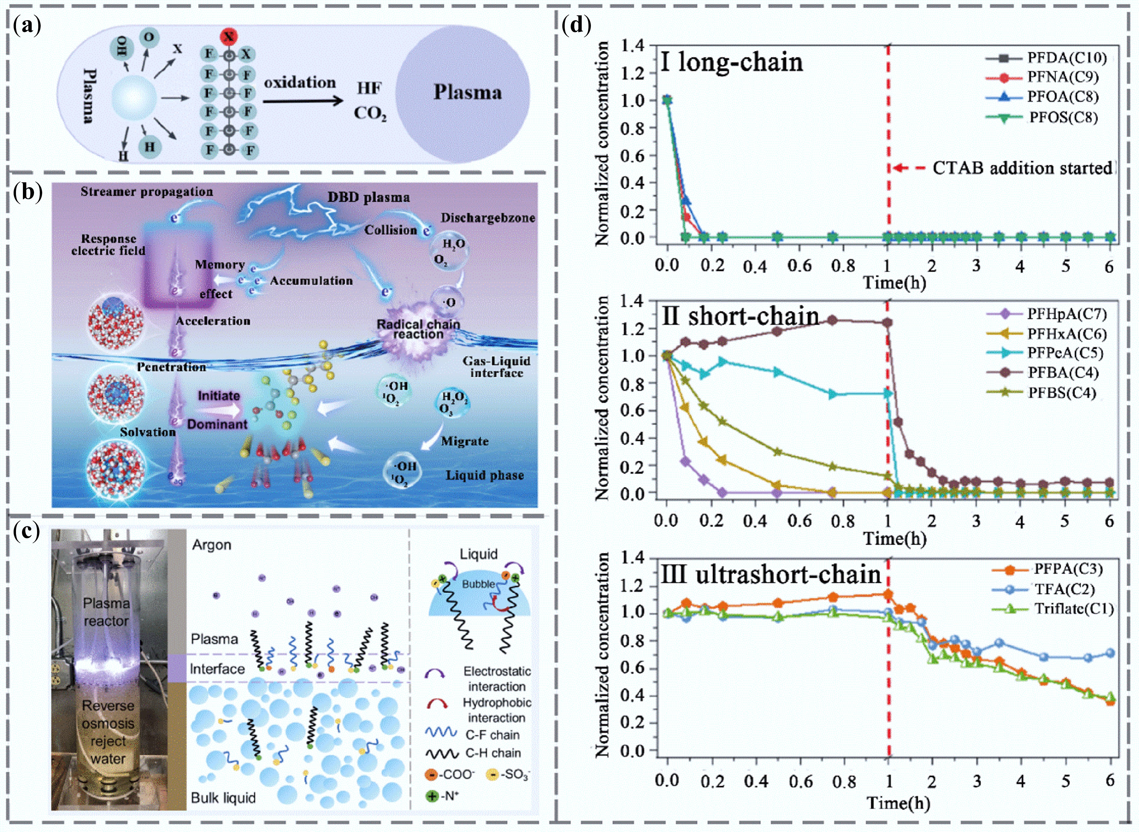
Figure 8.
Research progress of plasma technology for PFAS removal. (a) Plasma removal mechanism. (b) Schematic diagram of PFOA degradation initiated by electrons in DBD plasma[105]. (c) Degradation mechanism of PFAS in RO wastewater by plasma[106]. (d) Degradation rates of (I) long-chain, (II) short-chain, and (III) ultra-short-chain PFAS in RO wastewater by plasma[106].
-
Technology Target PFAS Degradation
efficiencyDefluorination rate Scalability
potentialEnergy
consumptionAdsorption Medium- to long-chain,emerging PFAS 72%–100% < 10% High Low Membrane separation Most PFAS species 80%–99.99% < 10% Moderate Medium Electrochemical treatment All PFAS chain lengths > 67% 16.7%– ~100% High High UV-AOP/ARP PFOA, PFOS, emerging PFAS > 85.3% 40% – ~100% Moderate High Photocatalysis PFOA, PFOS, emerging PFAS 70%– ~100% 16.5%–100% High Medium–high Thermal decomposition Almost all PFAS, including short-chain 90%–100% 30%–100% Low Extremely high Ultrasonic oxidation PFOS, PFOA, some short-chain PFAS 28.0%–93.4% 33.84%–95% Low High Plasma treatment Broad-spectrum PFAS 32%–99% 10%–80% Medium–high High Table 1.
Performance comparison of PFAS removal technologies
-
Technology Advantage Disadvantage Adsorption Low cost, simple operation, high selectivity Does not degrade PFAS; only transfers contaminants Membrane separation Highly efficient retention, applicable to a wide range of PFAS Prone to membrane fouling; requires regular replacement Electrochemical treatment Enables complete mineralization, effective for full degradation Expensive anode materials, high energy demand UV-AOP/ARP Can be enhanced with oxidants/reductants to increase reactivity May generate toxic intermediate products Photocatalysis Suitable for solar-driven systems, environmentally friendly Catalyst instability and limited lifespan Thermal decomposition Completely destroys PFAS structures Requires high-temperature and high-pressure equipment Ultrasonic oxidation No need for chemical reagents, relatively safe operation Efficiency highly dependent on solution composition Plasma treatment Strong mineralization potential, effective across diverse PFAS types Complex equipment, requires precise operational control Table 2.
Advantages and disadvantages of PFAS treatment technologies
-
Comparison dimension Traditional PFAS (e.g., PFOA, PFOS) Emerging alternative (e.g. F-53B, HFPO-DA) Treatment difficulty Treatment technologies are relatively mature with extensive literature support; several processes (e.g., activated carbon, RO, electrochemical) are industrialized More structurally complex; conventional technologies show lower removal efficiency; higher water solubility complicates adsorption Degradation pathway Typically begins at carboxylic or sulfonic acid groups; involves α-C cleavage, decarboxylation, and sequential C–F bond breakage More diverse, involving ether linkages and branched structures; may include oxidative/reductive mechanisms and persistent intermediates Environmental persistence Long half-life, high mobility, and bioaccumulative in aquatic/biological environments Often more persistent; short-chain products are highly mobile and difficult to detect Defluorination efficiency 16%–100% possible with chemical methods Generally < 50%, but Genx can sometimes achieve a 90% rate, intermediate products may pose unknown risks Adsorption behavior Strong affinity for activated carbon and ion-exchange resins Weak interaction with conventional adsorbents; lower adsorption capacity Analytical challenges Well-established detection standards and databases No unified detection protocol; often requires high-resolution, non-targeted analysis Table 3.
Comparative analysis of traditional and emerging PFAS
Figures
(8)
Tables
(3)