-
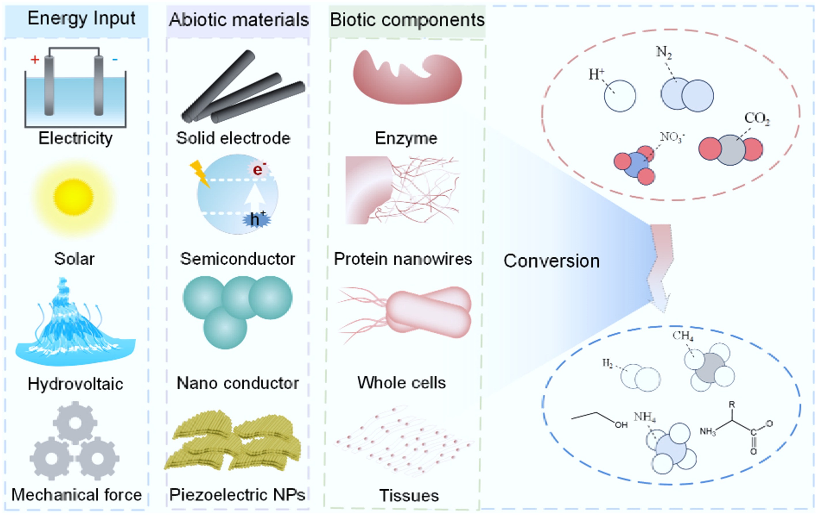
Figure 1.
Biohybrids for sustainable chemical synthesis. These systems leverage diverse energy inputs, a wide range of abiotic materials, and various biotic components to produce valuable products from multiple substrates.
-
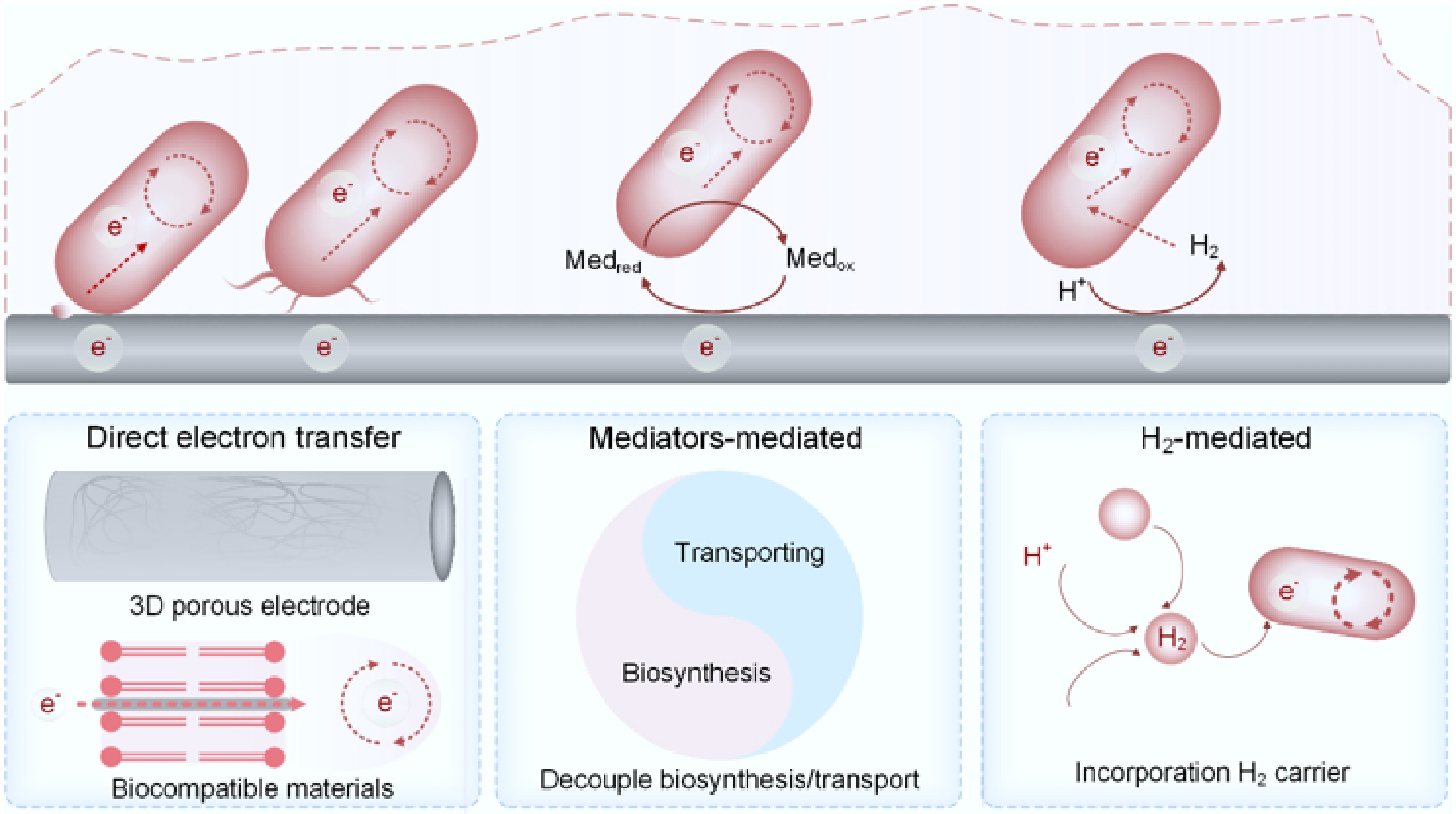
Figure 2.
MES based on biocathode architectures and strategies to address their limitations.
-
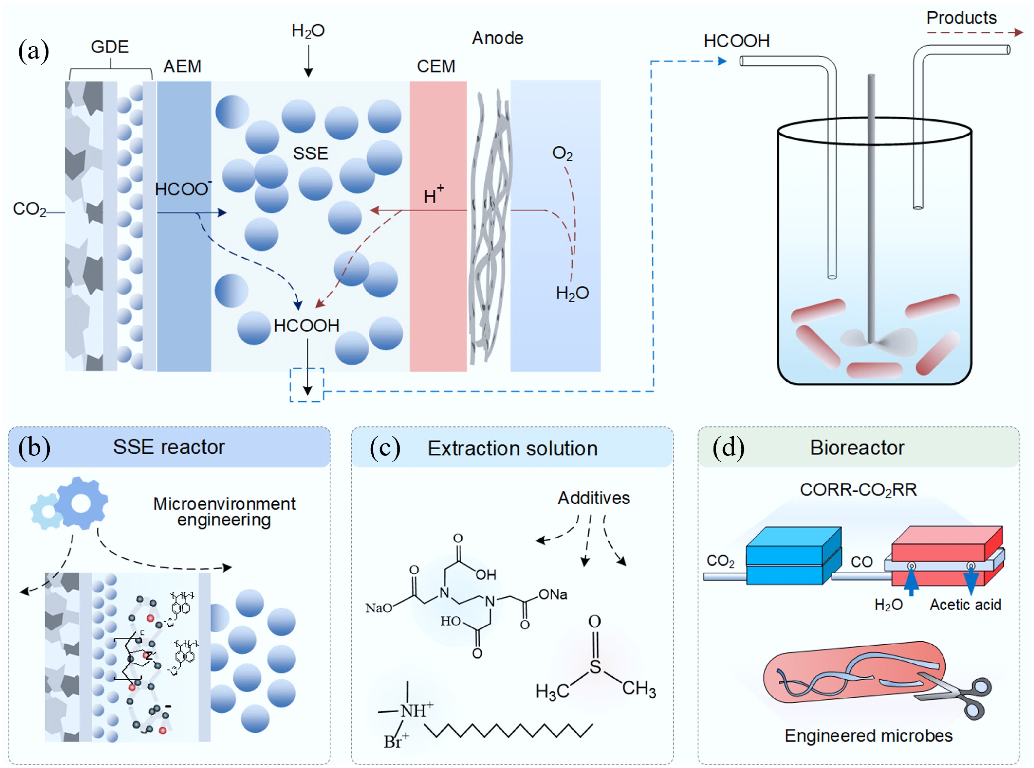
Figure 3.
SSE-based electrocatalytic–biocatalytic tandem systems and strategies to address the associated limitations. (a) Schematic illustration of an SSE-based electrocatalytic–biocatalytic tandem system. (b) Rational modulation of the interfacial microenvironment to improve the CO2 reduction efficiency. (c) Application of chemical additives to enhance CO2 reduction performance, with consideration of their potential impacts on microbial metabolism. (d) Two-step conversion pathway in which CO2 is first reduced to CO, followed by microbial conversion of CO to acetate; alternatively, this process can be facilitated by genetically engineered microbial strains.
-
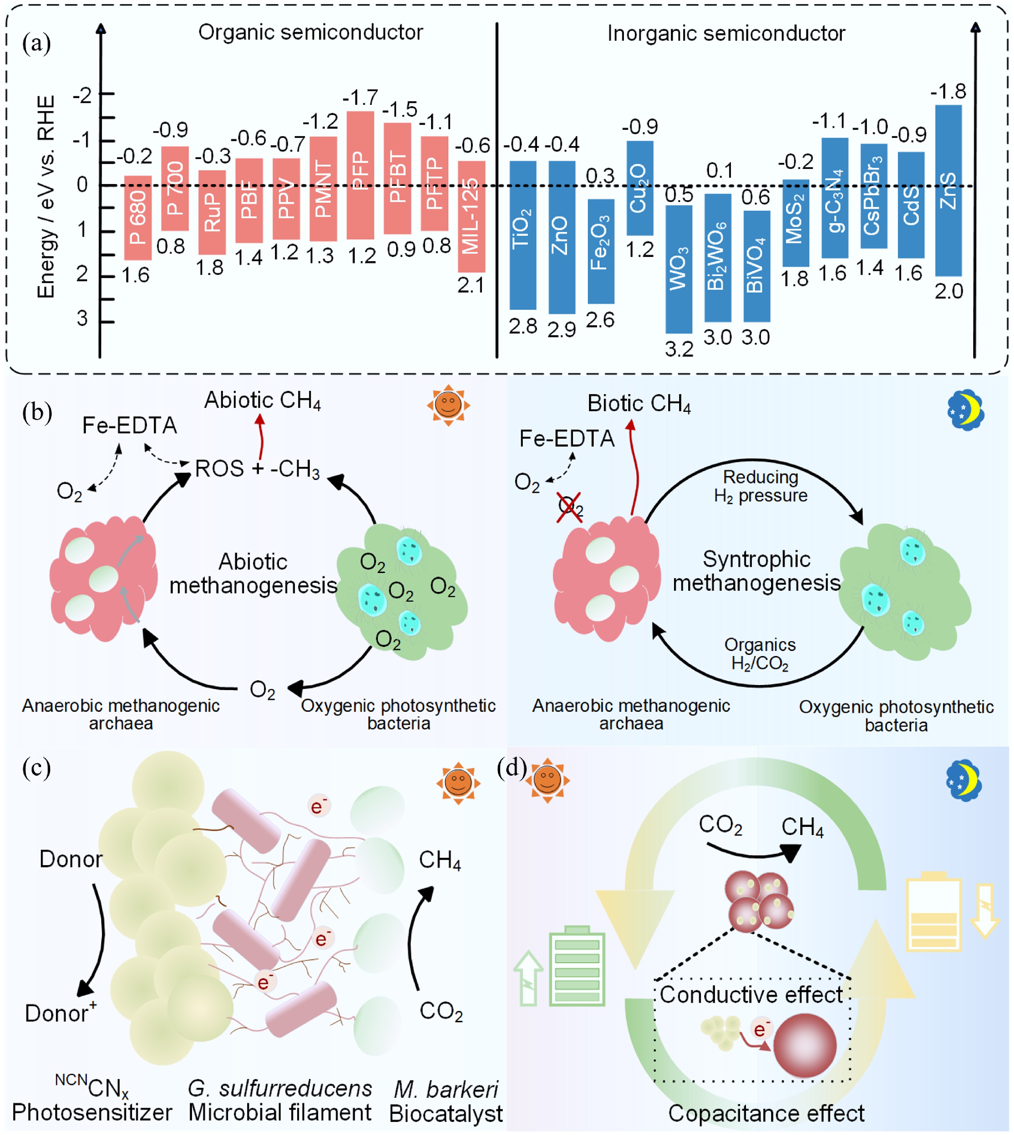
Figure 4.
Representative organic and inorganic semiconductors and studies on semi-artificial photosynthetic systems. (a) The conduction band (CB) and valence band (VB) of common semiconductors. Reproduced with permission from Song et al.[53]. (b) Biotic and abiotic CH4 production under anoxic dark and oxic light conditions with oxygenic photosynthetic bacteria. Reproduced with permission from Ye et al.[180]. (c) Engineering a microbial ecosystem to balance electron generation and utilization. Reproduced with permission from Kalathil et al.[167]. (d) Capacitive modification of biohybrid interfaces. Reproduced with permission from Hu et al.[166].
-
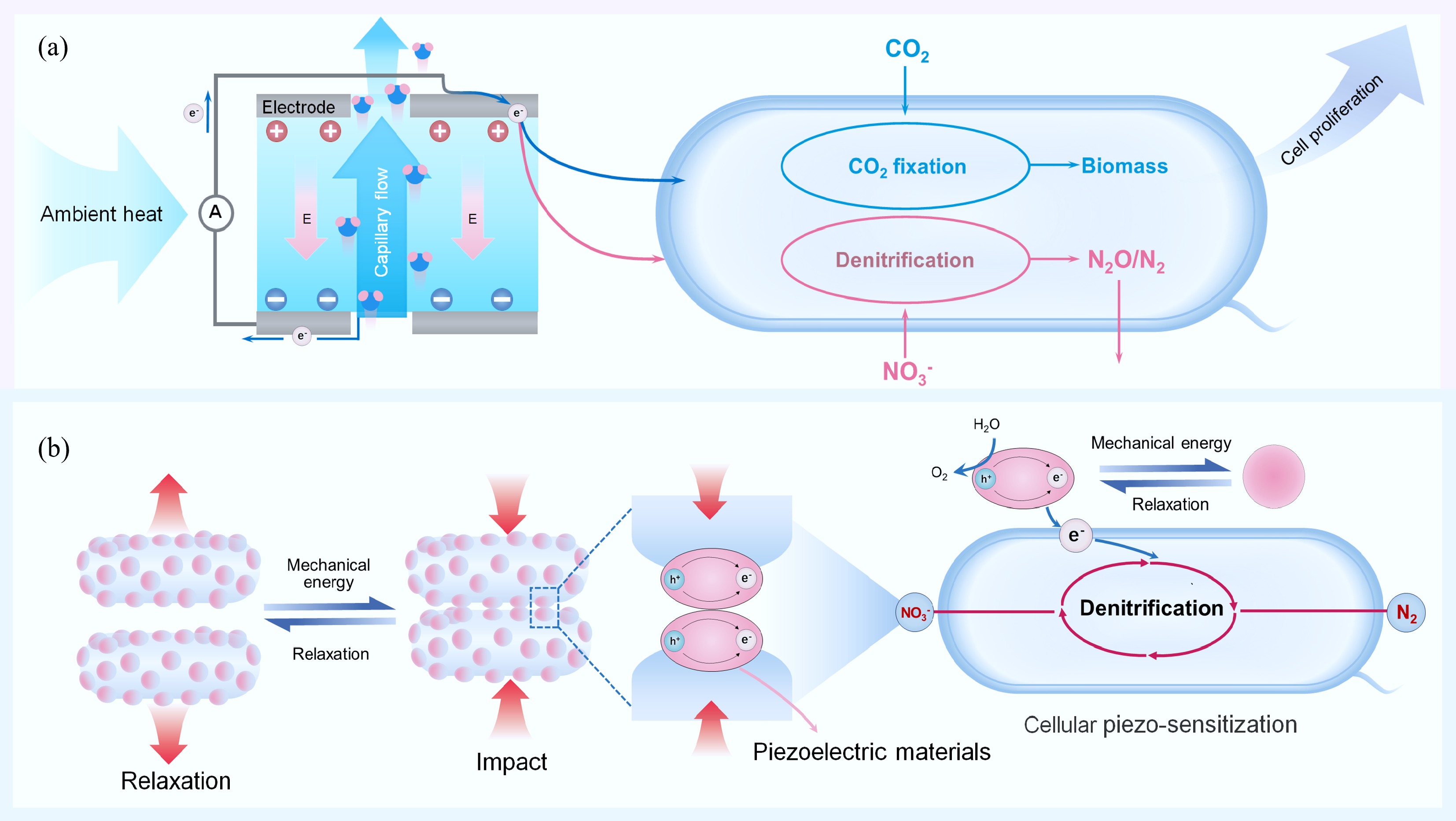
Figure 5.
Biohybrids with hydrovoltaic energy and mechanical energy input. (a) Schematic diagram of hydrovoltaic electron generation within a biofilm supporting microbial growth. Reproduced with permission from Ren et al.[191]. (b) Schematic diagram of mechanically driven denitrification. Reproduced with permission from Ye et al.[192].
-
Items MES systems based on biocathode structures Semi-artificial photosynthetic systems Energy input Direct current electricity Solar Abiotic materials Electrode Semiconductor Biofilm attachment Yes Not necessary Table 1.
Comparison of MES systems based on biocathode structures and semi-artificial photosynthetic systems
-
Microorganisms Photosensitizer Products Ref. M. barkeri CdS CH4 [163,164] M. barkeri Ni: CdS CH4 [165] M. barkeri CNx CH4 [166−168] M. barkeri EGaIn CH4 [169] M. barkeri R. palustris CH4 [170] M. thermoacetica CdS Acetate [171,172] S. ovata Photocatalyst sheet Acetate [154] S. ovata Si nanoarrays Acetate [152] S. ovata InP/ZnSe/ZnS QDs Acetate [173] C. autoethanogenum CdS Acetate [156] S. oneidensis MR-1 CdS Acetate [174] E. coli CdS Formic acid [175] Azotobacter vinelandii CdS/CdSe/InP/
Cu2ZnSnS4@ZnSFormic acid [21] Cupriavidus necator CdS/CdSe/InP/
Cu2ZnSnS4@ZnSC2H4, PHB, IPA, BDO, MKs [21] Chlorella zofingiensis Gold nanoparticles Carotenoid [158] R. eutropha g-C3N4 PHB [176] R. eutropha Organic polymer dots PHB [177] X. autotrophicus CdTe Biomass [178] Synechococcus sp. Poly(fluorene-co-phenylene) derivative (PFP) Biomass [179] Polyhydroxybutyrate, PHB; isopropanol, IPA; 2,3-butanediol, BDO; methyl ketones, MKs; polymeric carbon nitride, CNx; eutectic gallium–indium alloys, EGaIn. Table 2.
Summary of reported semi-artificial photosynthetic systems for chemical synthesis from valorization of CO2
Figures
(5)
Tables
(2)