-
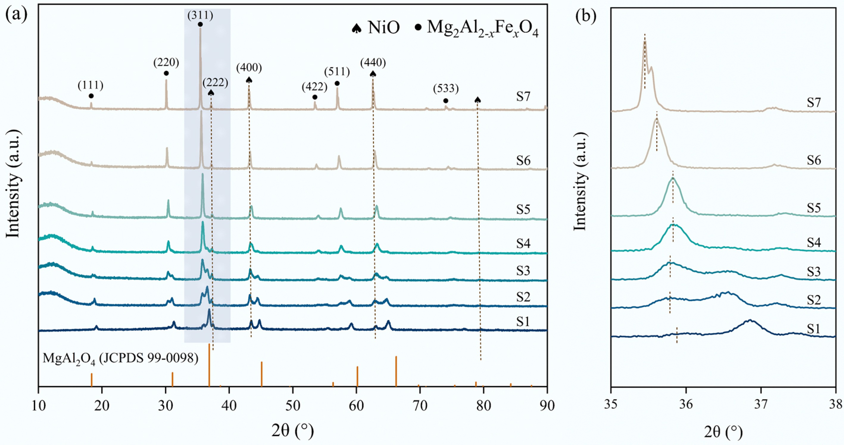
Figure 1.
XRD patterns of (a) fresh NiO/MgAl2-xFexO4 (S1−S7); (b) local magnified XRD patterns.
-
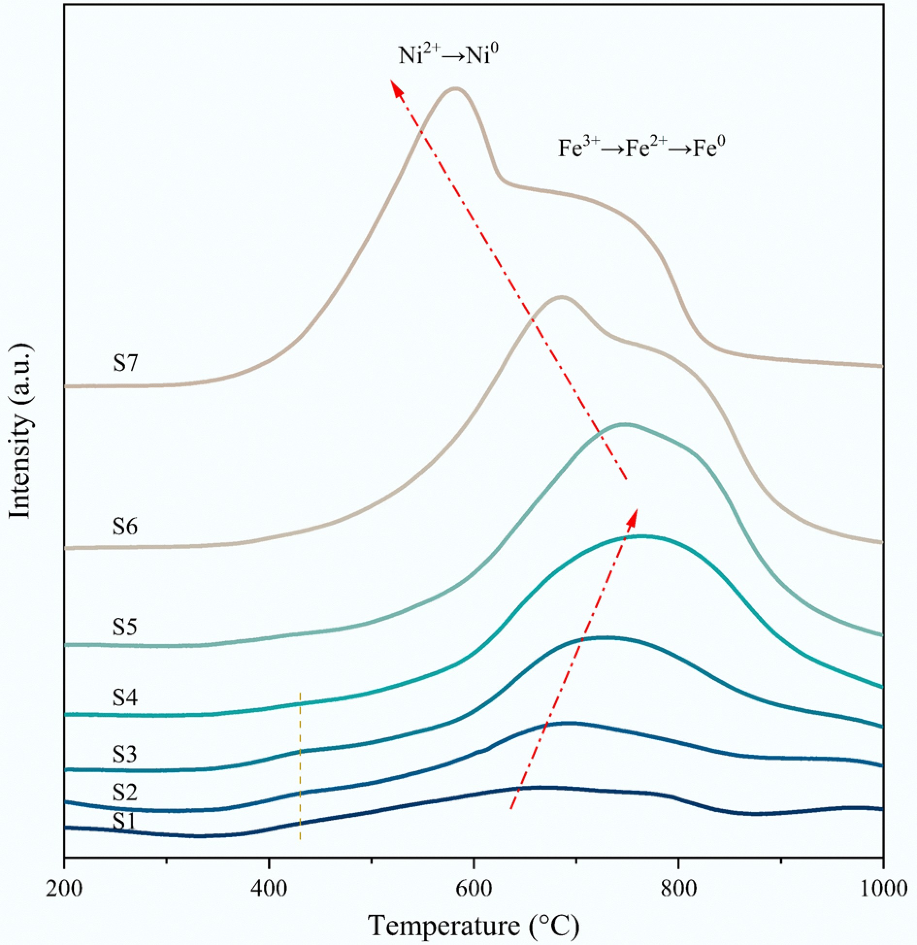
Figure 2.
H2-TPR profiles of as-synthesized NiO/MgAl2-xFexO4 samples.
-
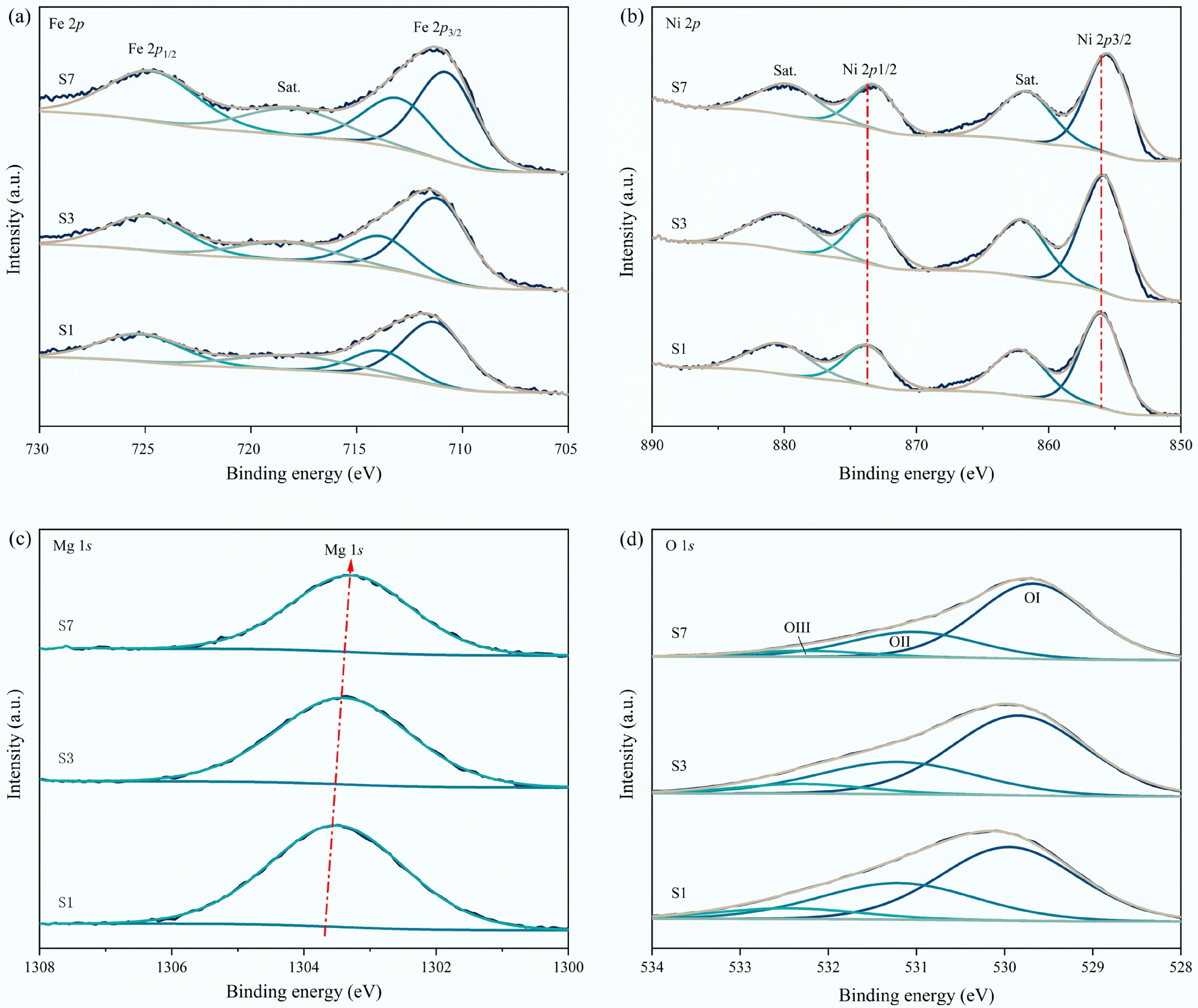
Figure 3.
XPS analysis of fresh S1, S3, and S7 catalysts. (a) Fe 2p; (b) Ni 2p; (c) Mg 1s, and (d) O 1s.
-
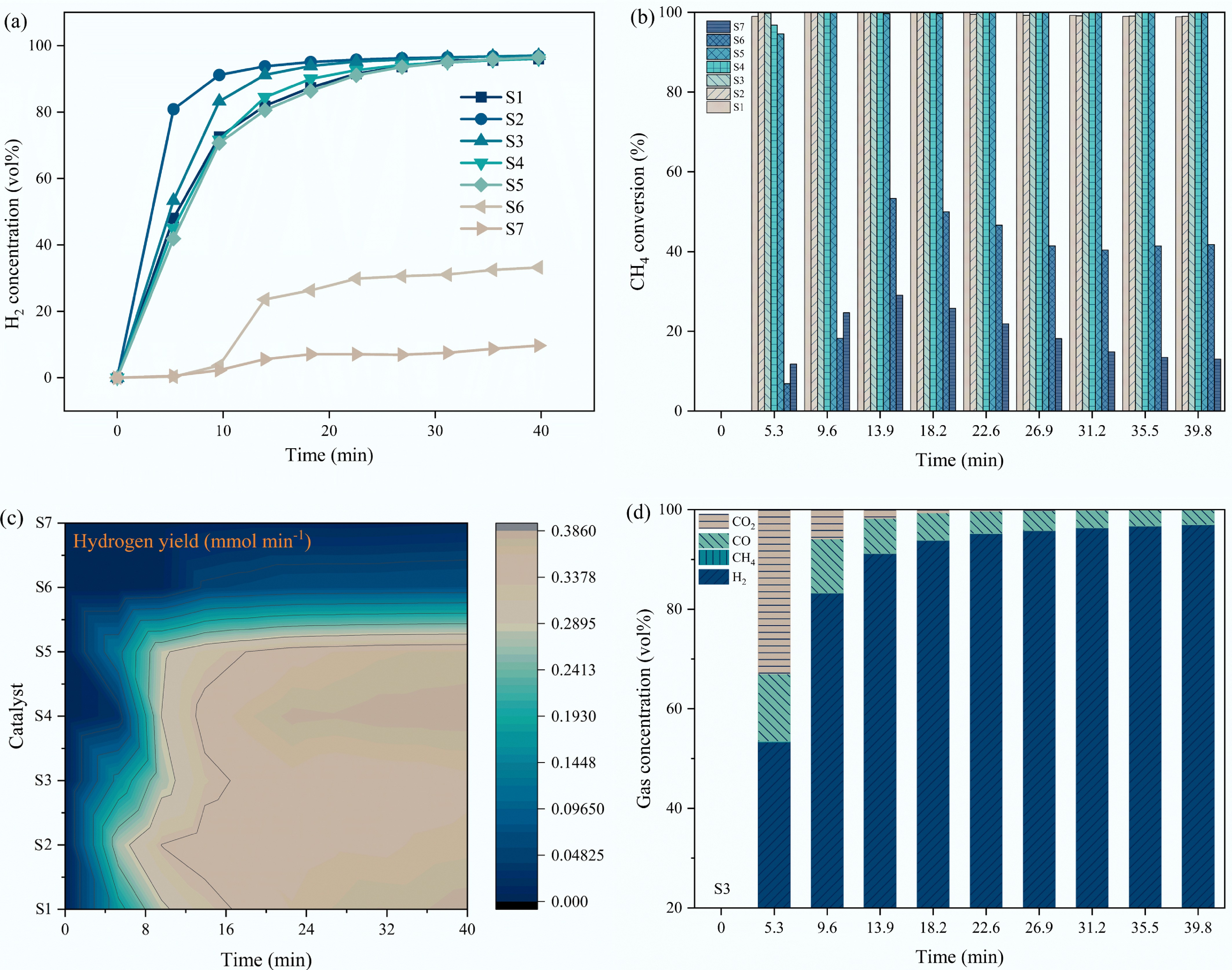
Figure 4.
Effect of Fe doping on the (a) H2 concentration; (b) CH4 conversion; (c) H2 yield; (d) gas concentration of H2, CH4, CO, CO2 under the catalysis of S3 catalyst.
-
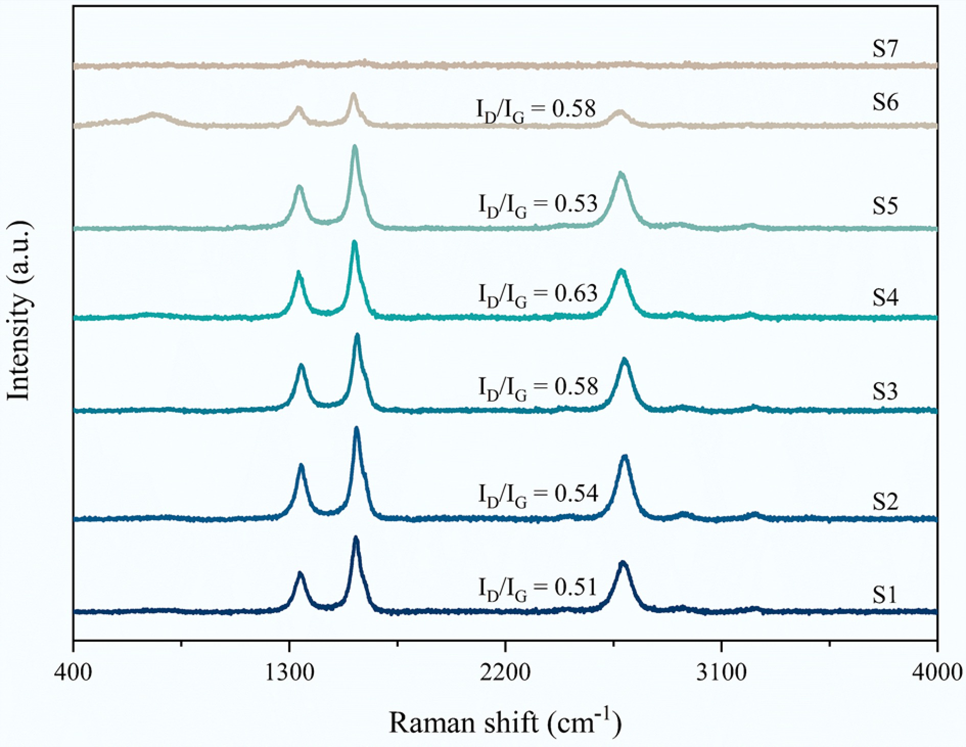
Figure 5.
Raman spectra of spent S1−S7 samples after 40 min CMD at 750 °C.
-
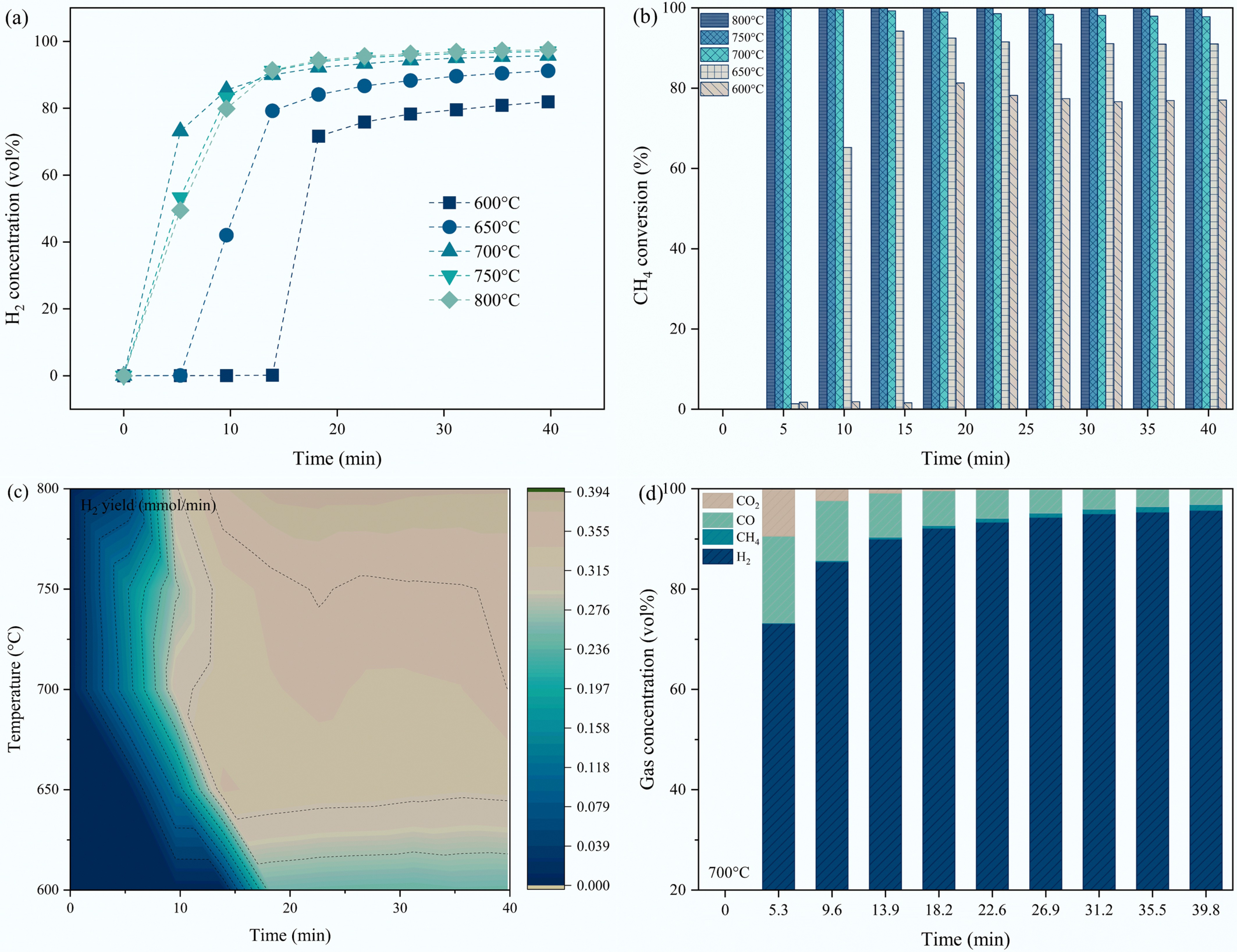
Figure 6.
Effect of methane decomposition temperatures on (a) H2 concentration; (b) CH4 conversion; (c) H2 yield using S3 sample; (d) the gas concentrations of H2, CH4, CO, CO2 under S3 catalyst at 700 °C.
-
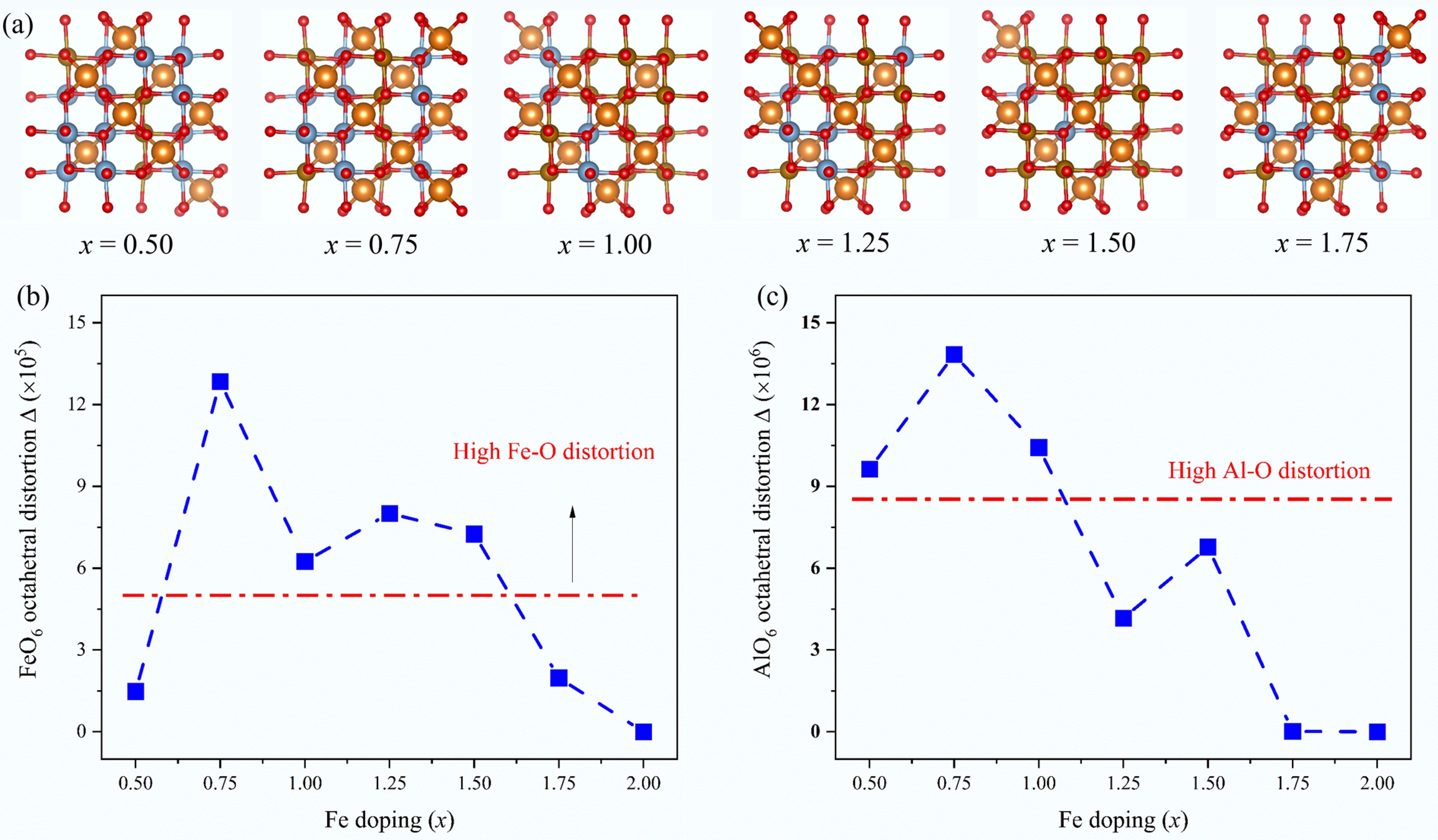
Figure 7.
Lattice distortion analysis: (a) bond structure of MgAl2-xFexO4, x = 0.50, 0.75, 1.00, 1.25, 1.50, and 1.75, corresponding to MgAl1.50Fe0.50O4, MgAl1.25Fe0.75O4, MgAl1.00Fe1.00O4, MgAl0.75Fe1.25O4, MgAl0.50Fe1.50O4, and MgAl0.25Fe1.75O4, respectively; (b) Fe(Al)O6 octahedral distortion as a function of Fe doping.
-
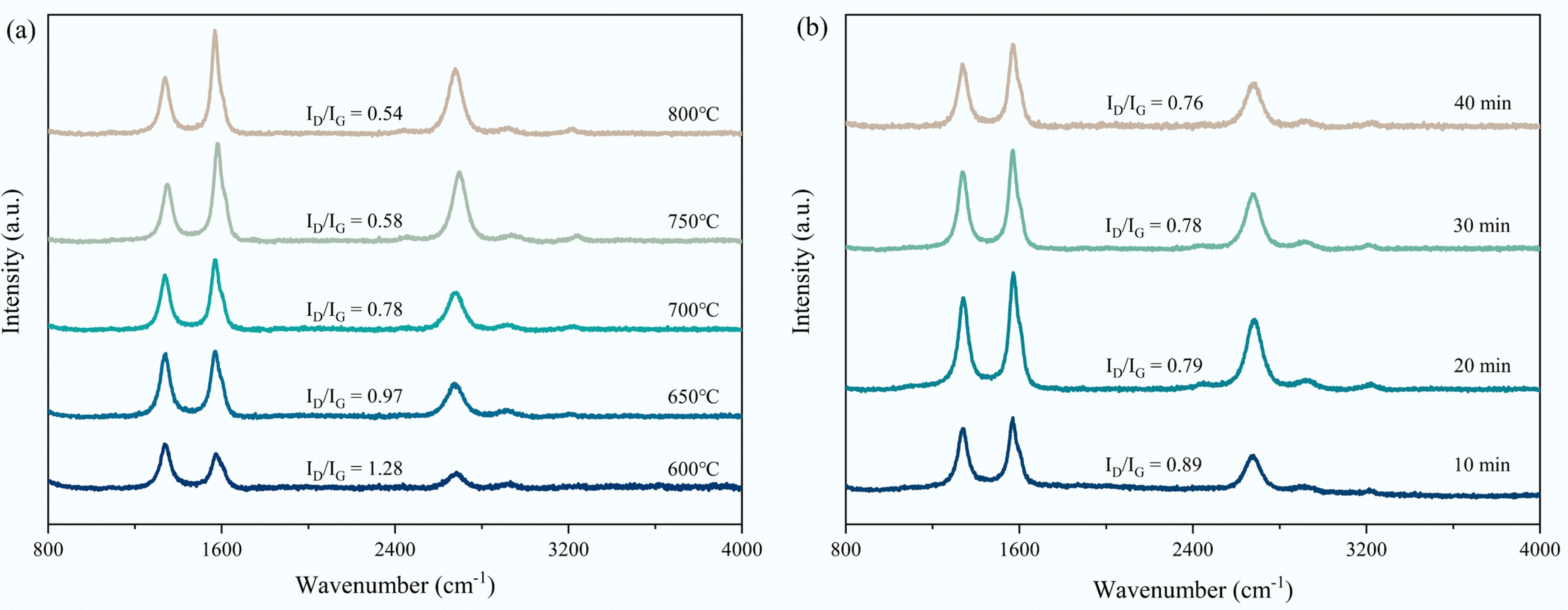
Figure 8.
Raman spectra of (a) spent S3 sample after 40 min CMD at 600−800 °C; (b) spent S3 sample after 10−40 min CMD at 700 °C.
-
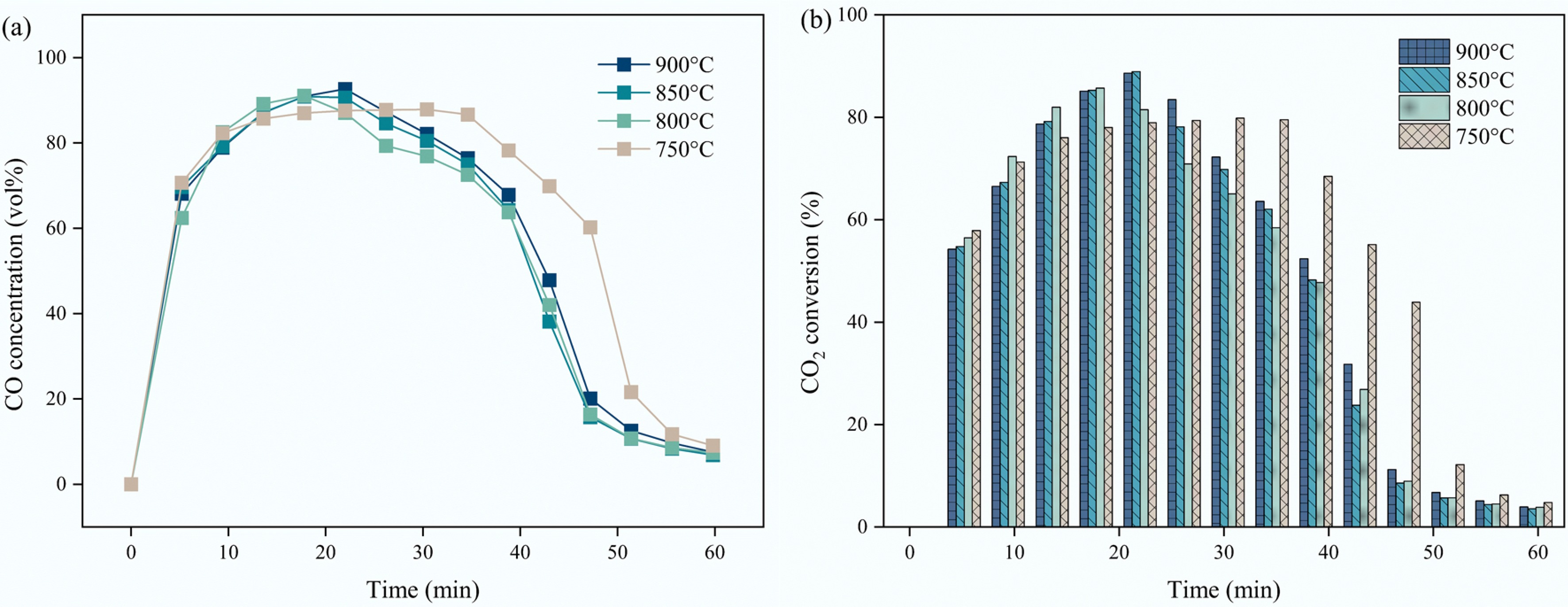
Figure 9.
Effect of carbon dioxide reduction temperatures on the (a) CO concentration; (b) CO2 conversion of S3 sample.
-
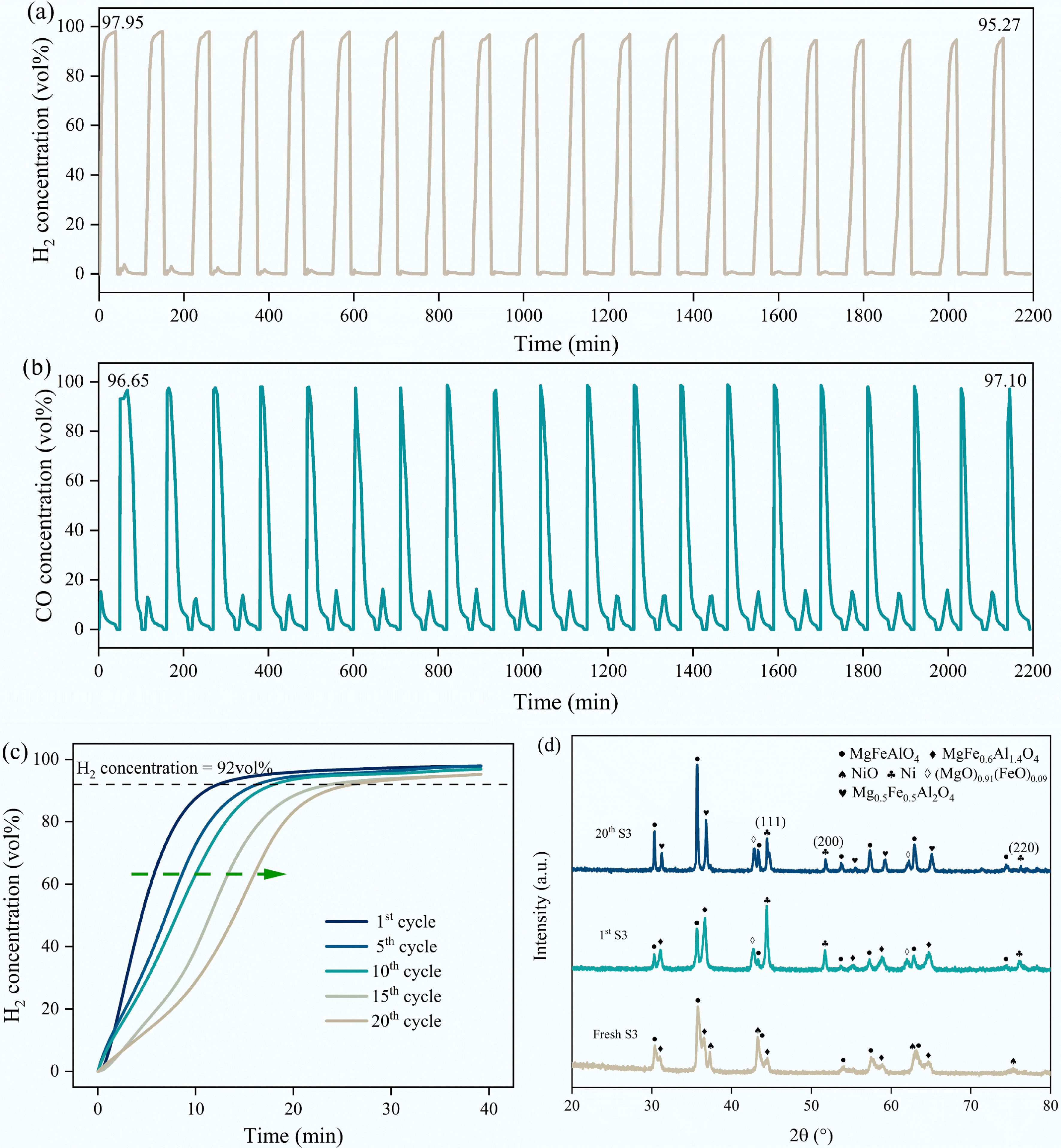
Figure 10.
Cyclic stability test of S3 sample: (a) H2 concentration during 20 cycles; (b) CO concentration during 20 cycles; (c) Variation of H2 concentration with time and catalyst activation time in the 1st, 5th, 10th, 15th, and 20th cycles (based on 92 vol% H2 concentration); (d) XRD patterns of significant stages within 20 cycles of reacted S3 sample.
-
Sample BET surface
area (m2/g)Pore volume (cm3/g) Average pore diameter (nm) NiO crystallite size (nm) S1 4.7 0.016 7.9 27.0 S2 3.6 0.012 5.0 20.3 S3 2.4 0.011 12.5 17.1 S4 3.4 0.016 12.6 16.0 S5 2.8 0.013 3.9 22.9 S6 2.3 0.010 3.5 34.1 S7 1.8 0.004 3.2 44.0 Table 1.
Textural properties of the fresh catalysts
-
Catalyst Binding energy (eV) Ratio OI/OII Ni 2p3/2 Mg 1s Al 2p Fe 2p3/2 OI OII OIII S1 856.0 1303.5 74.2 711.3 0.58 0.33 0.09 1.76 S3 855.8 1303.4 73.9 711.2 0.63 0.30 0.07 2.10 S7 855.5 1303.3 / 710.7 0.68 0.26 0.05 2.62 Table 2.
Summary of XPS characteristics of S1, S3, and S7 catalysts
Figures
(10)
Tables
(2)