-
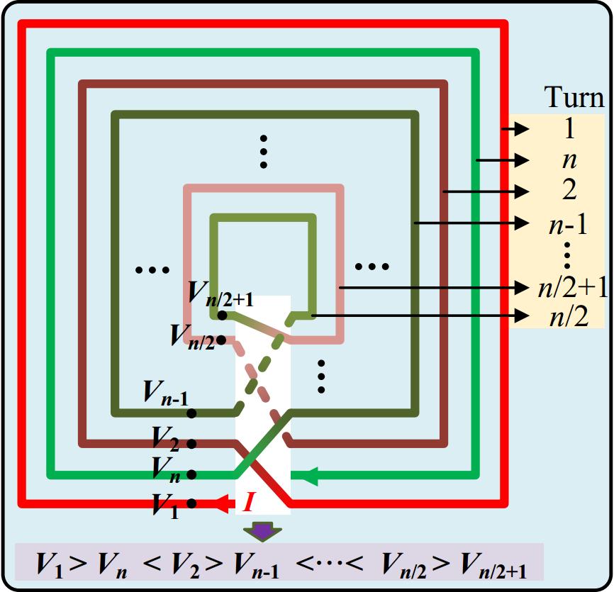
Figure 1.
Schematic diagram of alternating winding of inner and outer turns.
-
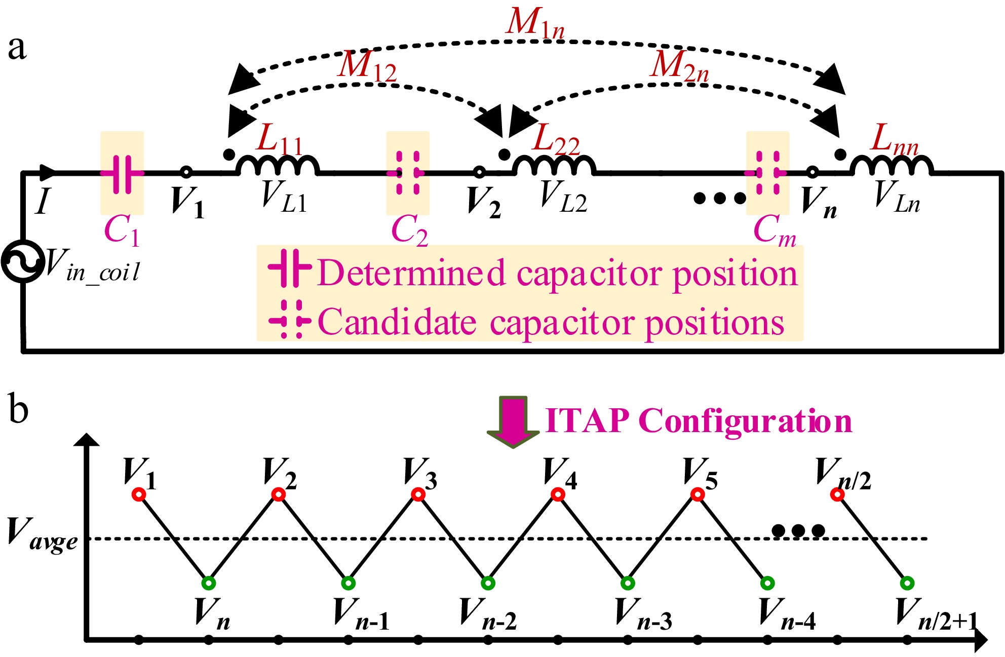
Figure 2.
Equivalent circuit of coil structure. (a) Equivalent circuit diagram. (b) Node voltage distribution diagram of the proposed method.
-
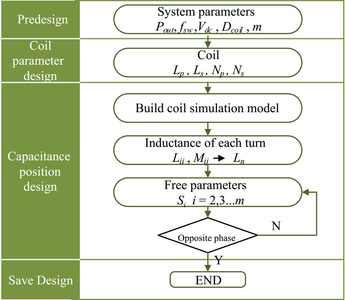
Figure 3.
Capacitor placement design procedure.
-
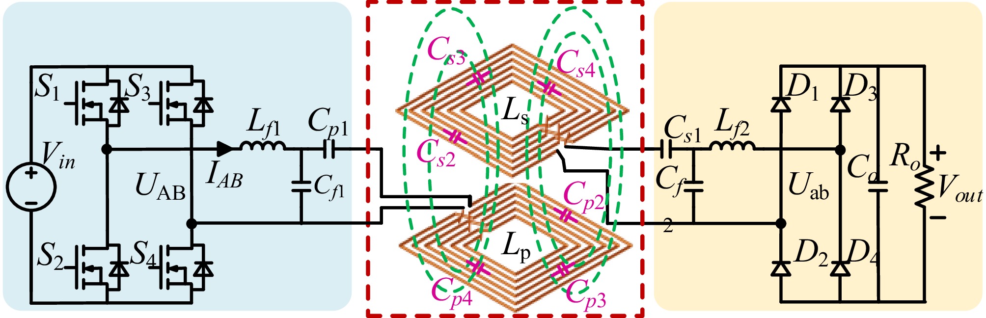
Figure 4.
Structural diagram of the interleaved winding coil system used in the ITAP method system.
-
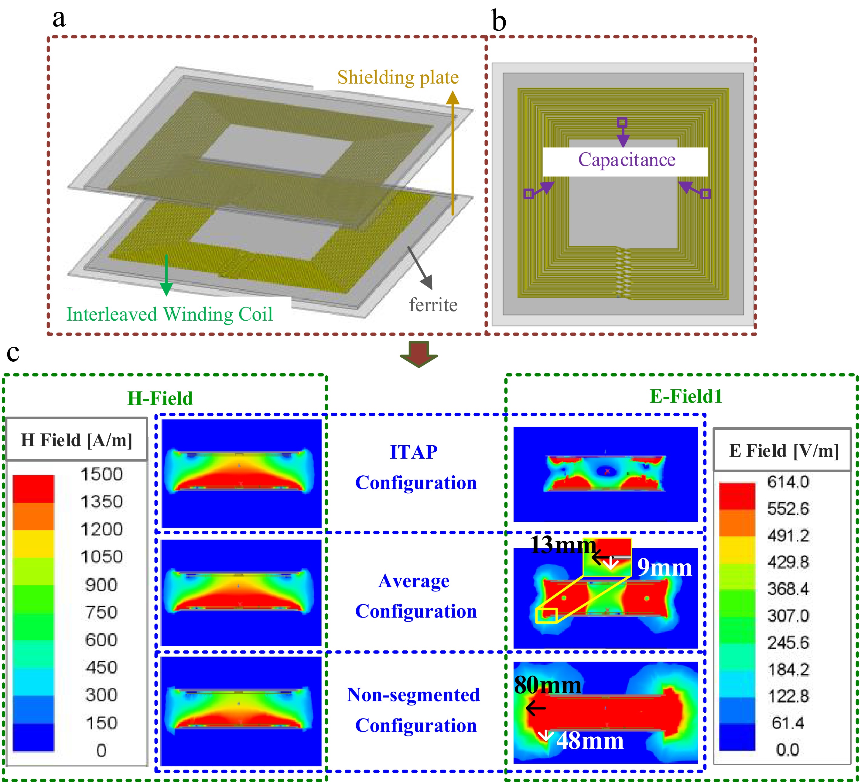
Figure 5.
(a) 3D simulation model of ITAP coil structure. (b) Top view of the transmitting coil and the position of the compensation capacitor. (c) Magnetic and electric field distribution.
-
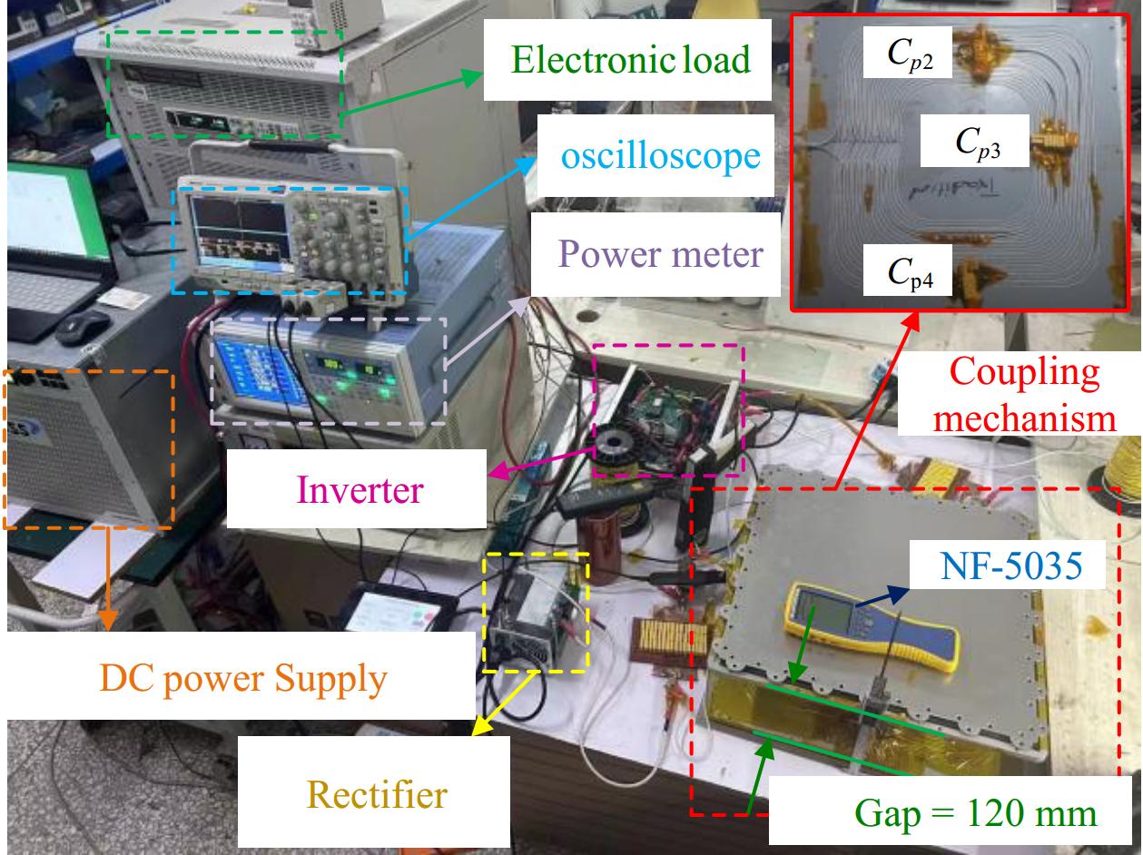
Figure 6.
Experimental setup.
-
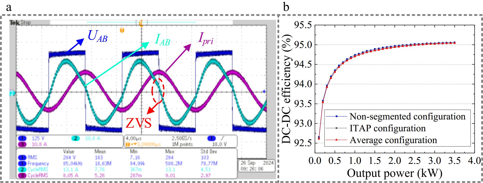
Figure 7.
The operating waveform of the ITAP system and the efficiency comparison curves.
-
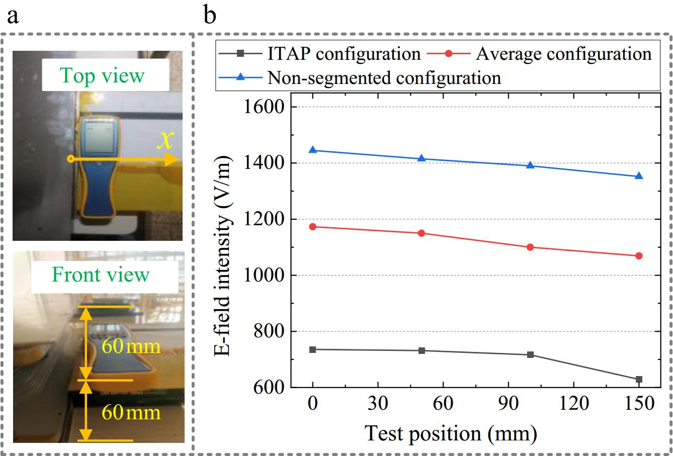
Figure 8.
The variation of transmission efficiency with output power.
-
Parameters Values Two-side coil currents 11.5 A/13 A Resonant frequency 85 kHz Shielding plate dimension 500 mm × 500 mm × 2 mm Ferrite core dimension 460 mm × 460 mm × 5 mm Coil dimension 400 mm × 400 mm × 2.5 mm Number of turns 22 turns Coil inductance 336.4 μH Cpi, Csi, i = 1, 2, 3, 4 45.6 nF Non-segmented capacitor value Cp 11.4 nF Table 1.
Coil setup parameters.
Figures
(8)
Tables
(1)