-
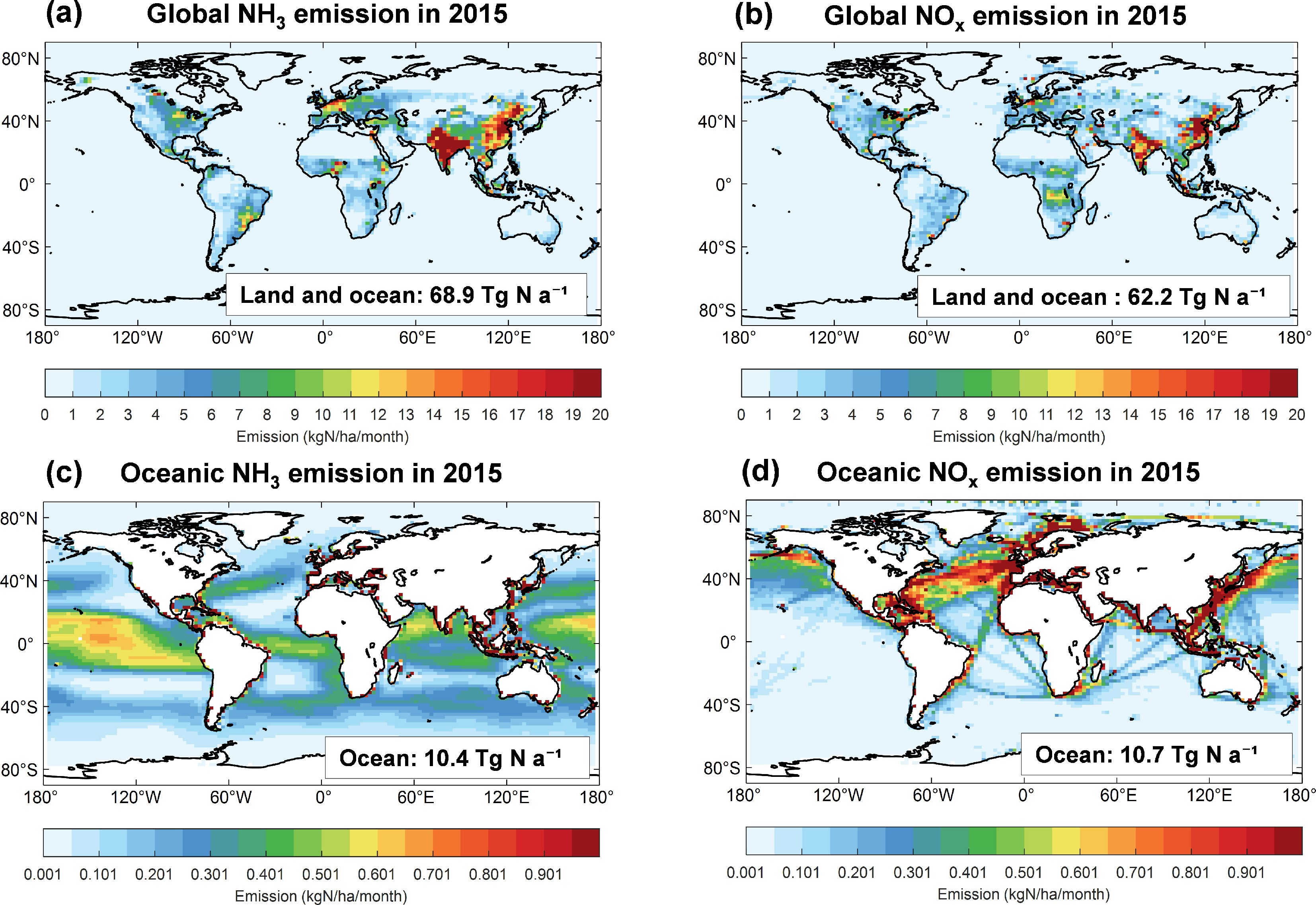
Figure 1.
Global and oceanic reactive nitrogen emissions in 2015. (a), (b) NH3 and NOx emissions from all sources (land and ocean); (c), (d) NH3 and NOx emissions from oceanic (marine) sources only, as a subset of the global totals.
-
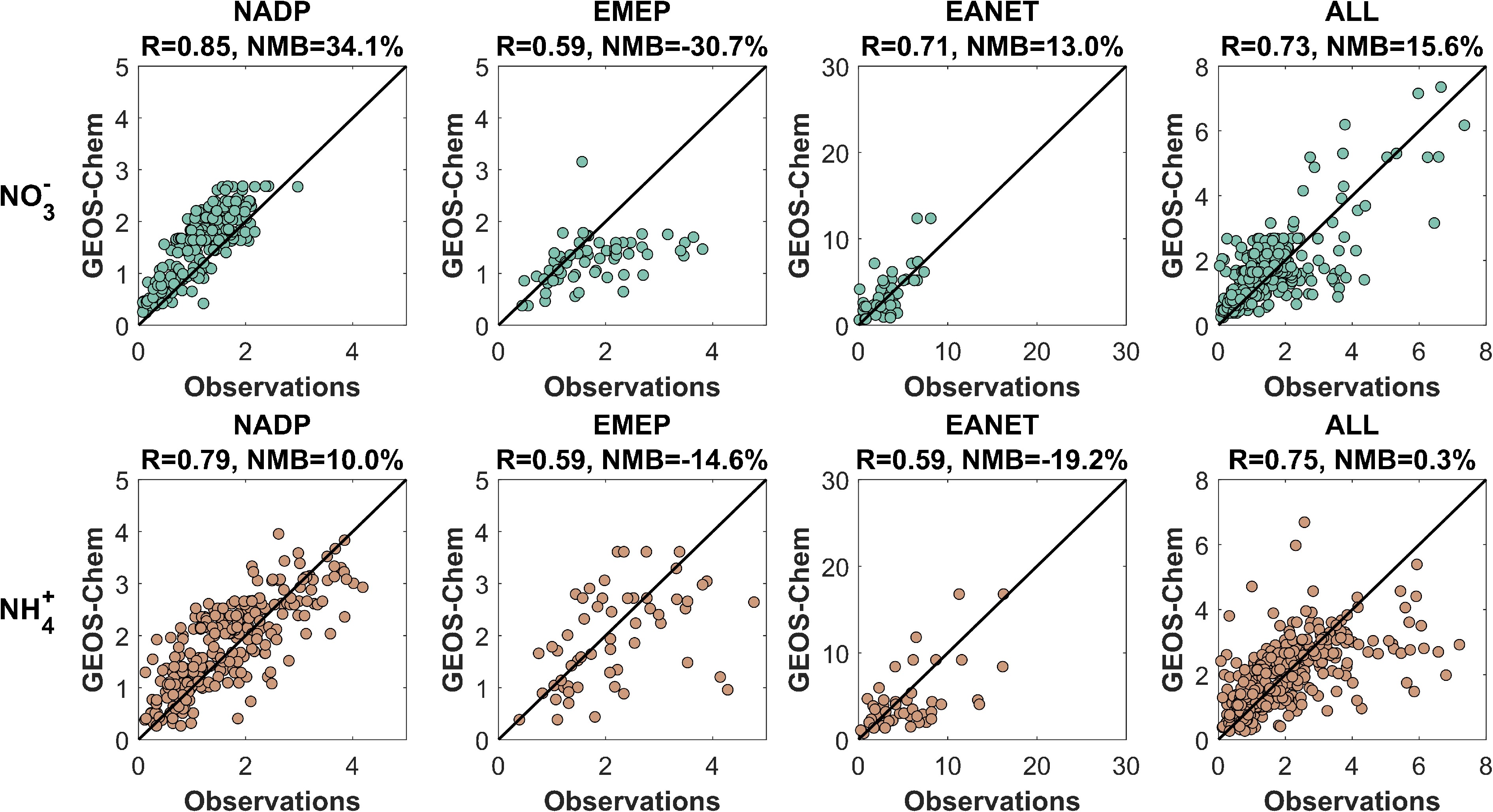
Figure 2.
Comparisons of observed and simulated wet nitrogen deposition fluxes. The first row shows NO3− wet deposition, and the second row shows NH4+ wet deposition in units of kg N ha−1 a−1. Model results are sampled along the observational stations from the NADP, EMEP, EANET, and combined networks.
-
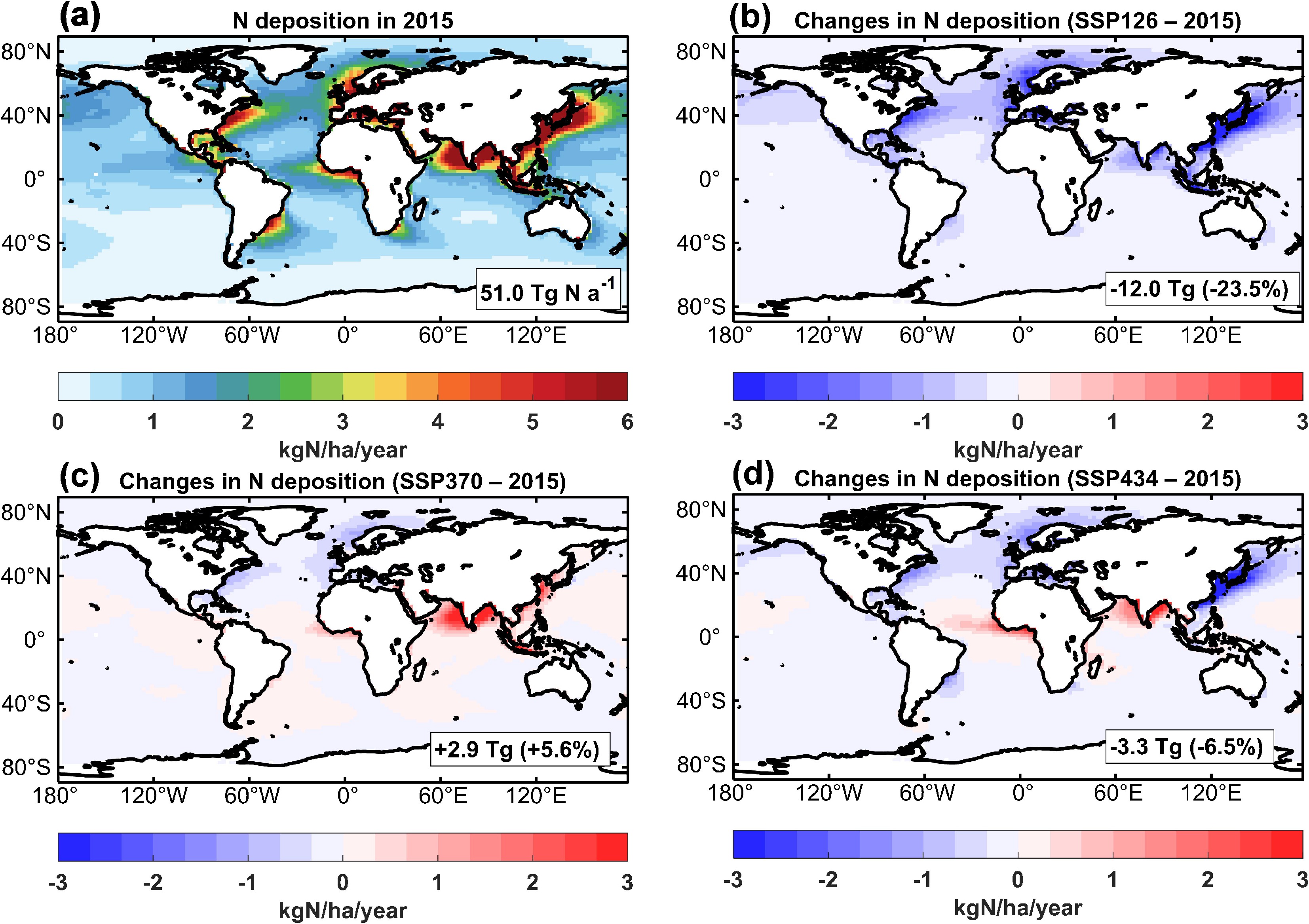
Figure 3.
(a) Model simulated spatial distribution of oceanic nitrogen deposition in 2015 and projected changes under future 2050 emission scenarios, including (b) SSP126, (c) SSP370, and (d) SSP434. The inset values are the total global oceanic nitrogen deposition or total changes (percentage changes in parentheses) relative to the 2015 condition.
-
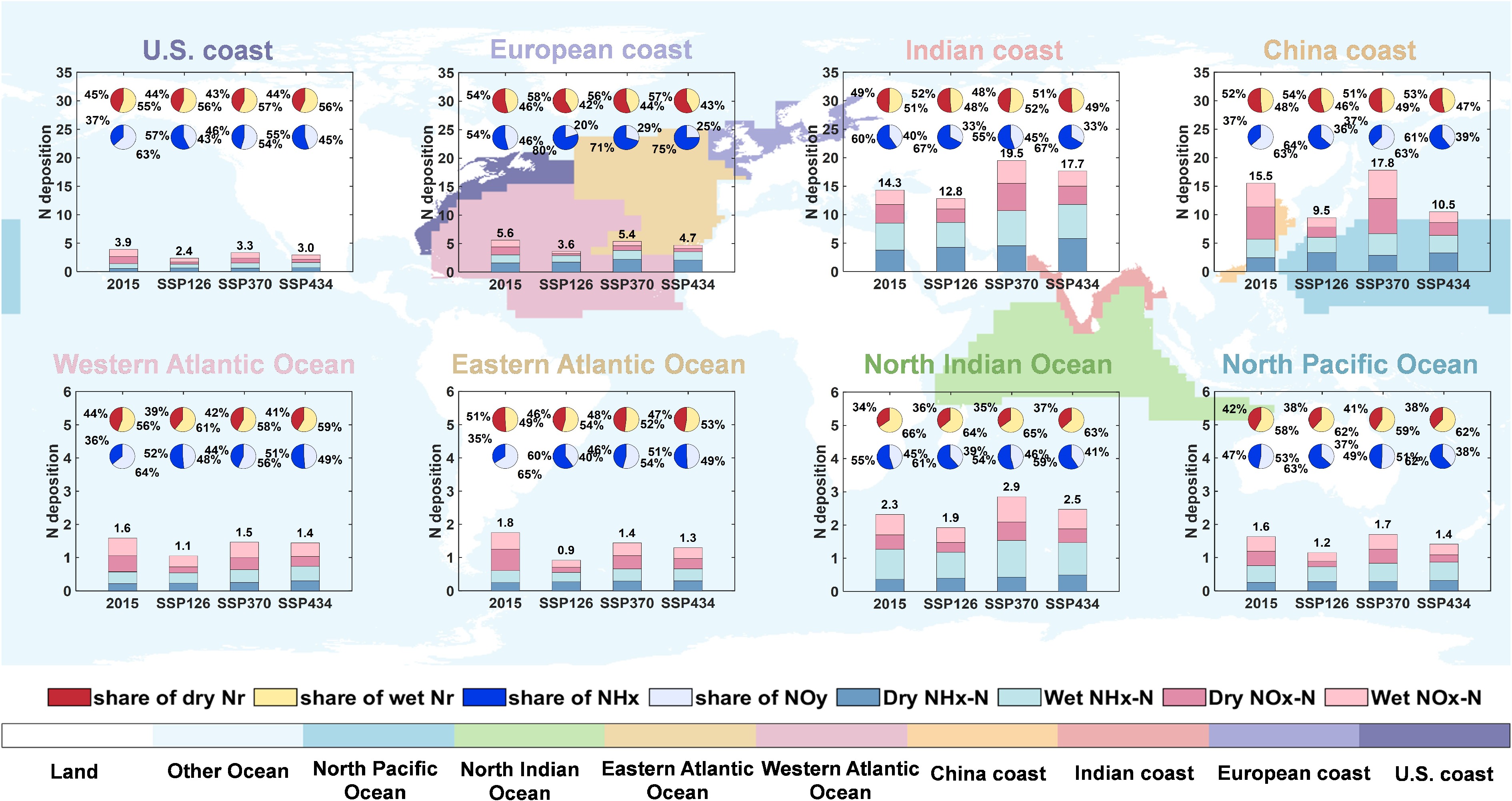
Figure 4.
Nitrogen deposition characteristics in representative ocean regions for 2015 and three 2050 scenarios. The underlying map shows geographic locations of ocean regions (also shown in Supplementary Fig. S1) investigated, including coastal areas (1st row from left to right: US coast, European coast, Indian coast, and China coast) and open oceans (2nd row from left to right: Western Atlantic Ocean, East Atlantic Ocean, North Indian Ocean, and North Pacific Ocean). In each panel, bars represent nitrogen deposition components (dry NHx, wet NHx, dry NOy, and wet NOy deposition) for 2015 and three future emission scenarios (SSP126, SSP370, and SSP434 for 2050). Pie charts show shares of dry vs wet deposition (1st row) and NHx vs NOy deposition (2nd row). All deposition values are expressed in kg N ha−1 a−1.
-
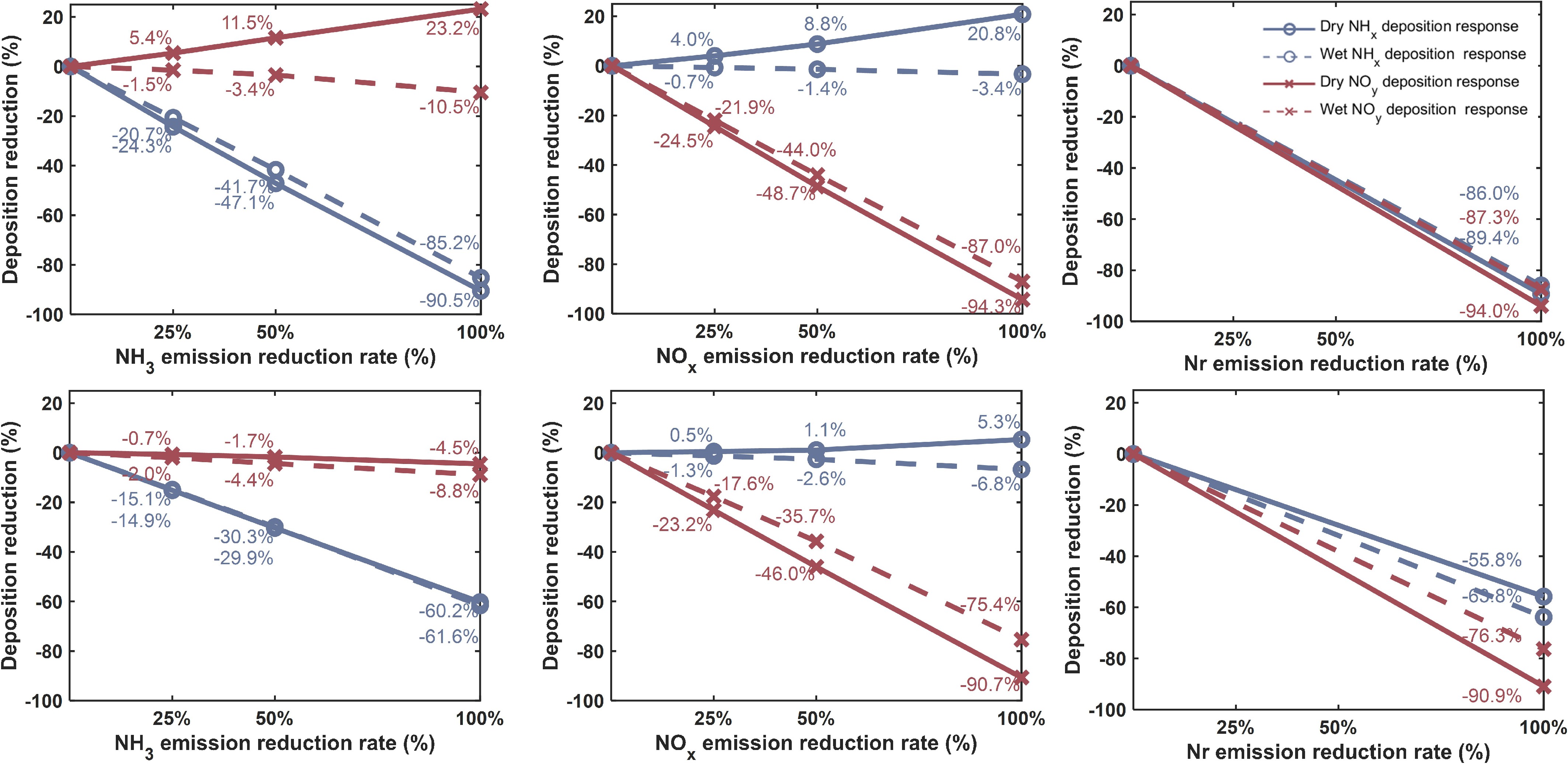
Figure 5.
Responses of oceanic nitrogen deposition to varying levels of anthropogenic NH3, NOx, and Nr emission reductions over the European coast (1st row) and Eastern Atlantic Ocean (2nd row) under the SSP126 2050 scenario. Relative changes in each nitrogen deposition component, including dry NHx (blue solid), wet NHx (blue dashed), dry NOy (red solid), and wet NOy (red dashed) driven by individual NH3 emission reductions (left column), NOx emission reductions (middle column), and joint Nr (NOx and NH3) emission reductions (right column). The inset numbers show the corresponding percentage changes for the specific reduction levels.
-
Scenarios Nitrogen deposition
(Tg N a−1)Potential oceanic productivity
(Tg C a−1)N2O-N
emissions
(Tg N a−1)Base (2015) 51.0 290 1.53 (1.16-1.89)1 SSP1-RCP2.6 (2050) 39.0 222 1.17 (0.89-1.45) SSP3-RCP7.0 (2050) 53.9 306 1.61 (1.23-2.00) SSP4-RCP3.4 (2050) 47.7 271 1.43 (1.1-1.77) 1The N2O emission range reflects the uncertainty in present-day N2O emission estimates given in Duce et al.[5]. Table 1.
Potential impacts of atmospheric nitrogen deposition on global ocean productivity and N2O emissions
Figures
(5)
Tables
(1)