-
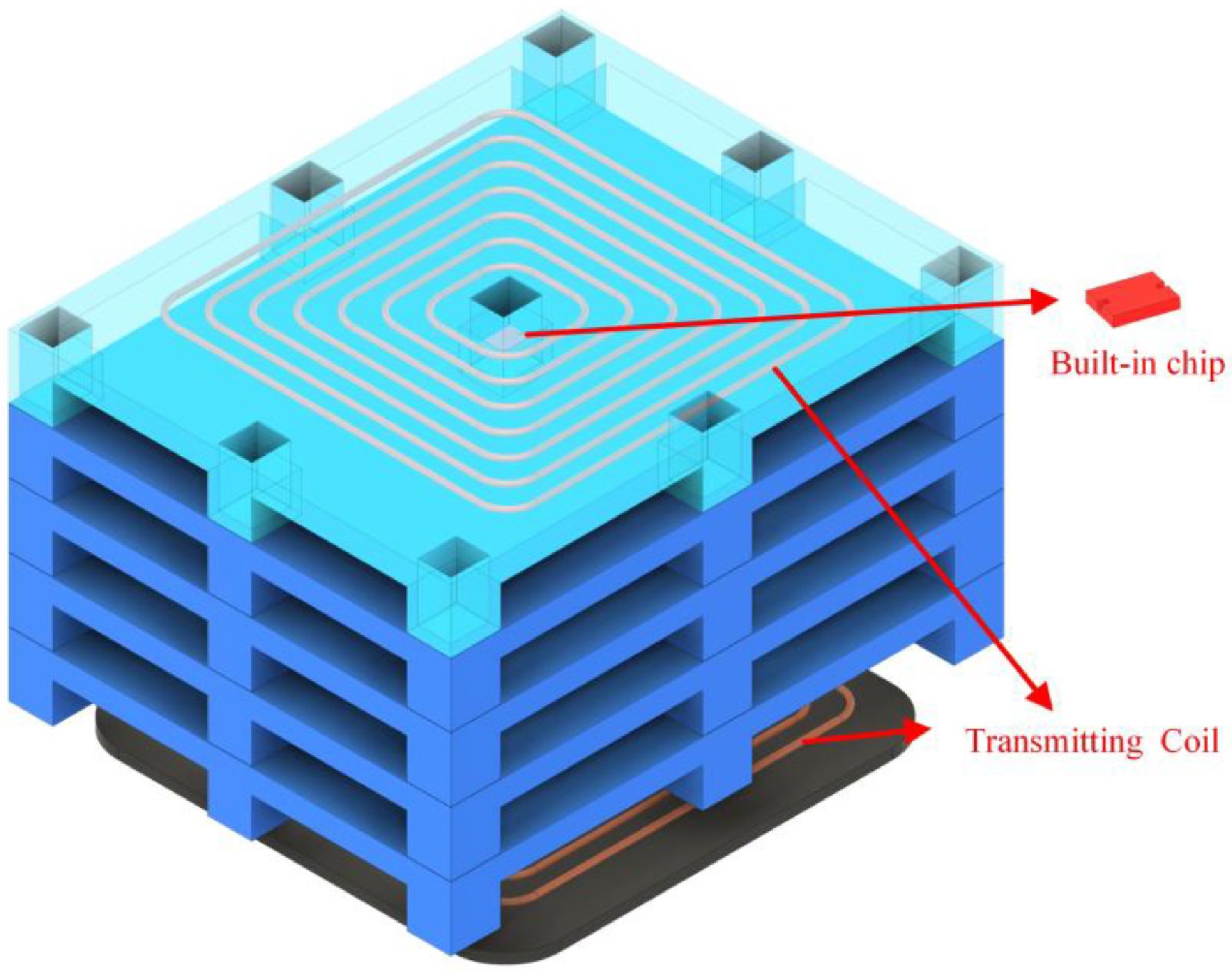
Figure 1.
Intelligent pallet placement schematic.
-
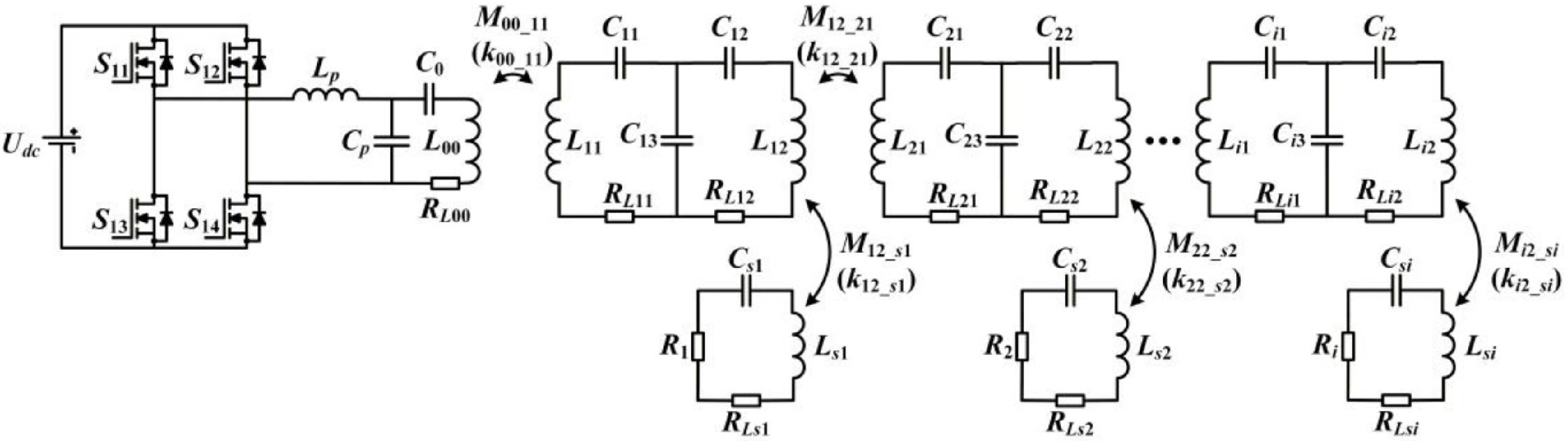
Figure 2.
Proposed multi-stage WPT system.
-
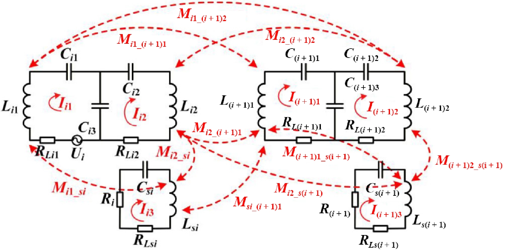
Figure 3.
Cross-coupling relationships of neighboring stages.
-
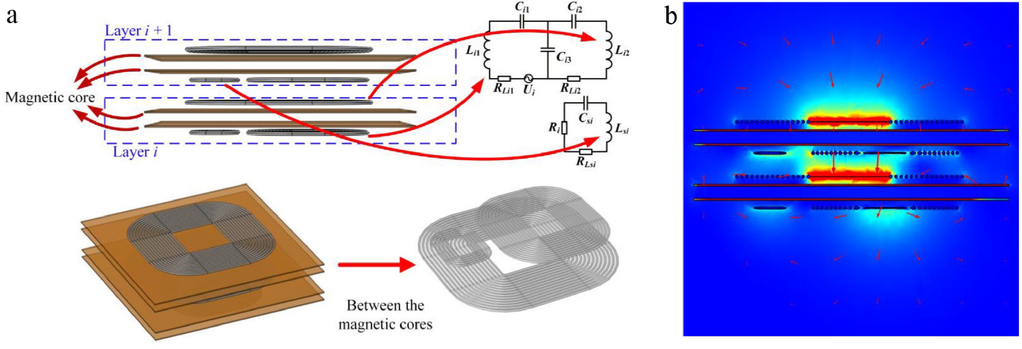
Figure 4.
Structure of the proposed decoupling model. (a) Coupling mechanism model. (b) Magnetic flux density distribution.
-
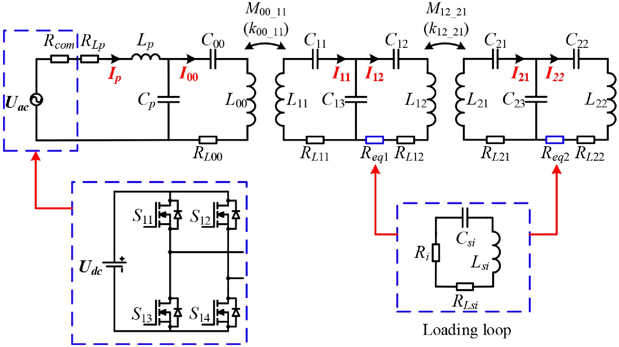
Figure 5.
Double loads equivalent system circuit.
-
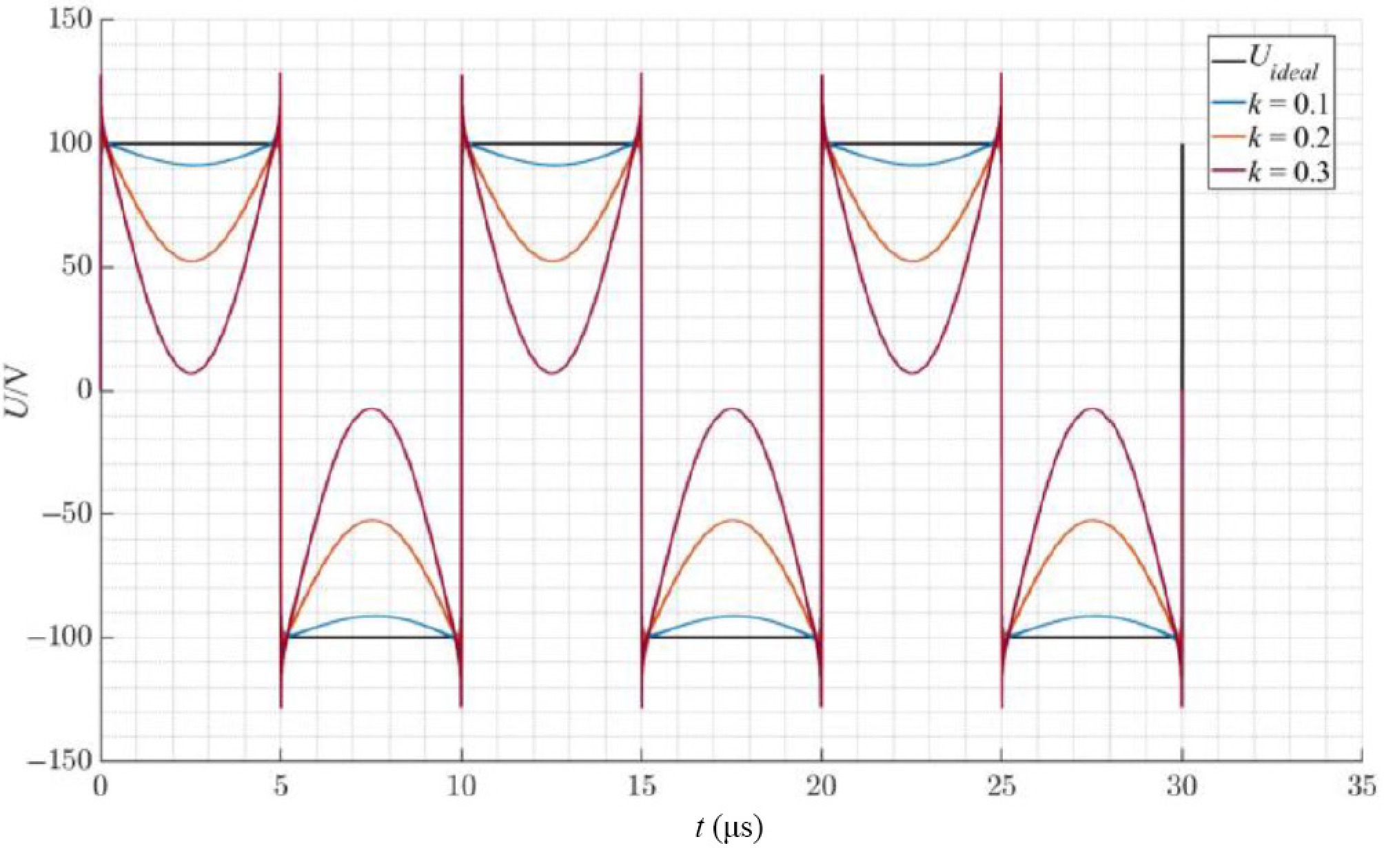
Figure 6.
Output voltage of inverter under different coupling coefficients.
-
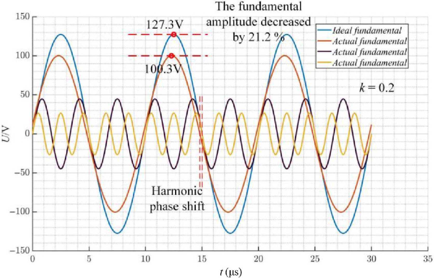
Figure 7.
Analysis of high harmonics of the output voltage of inverter.
-
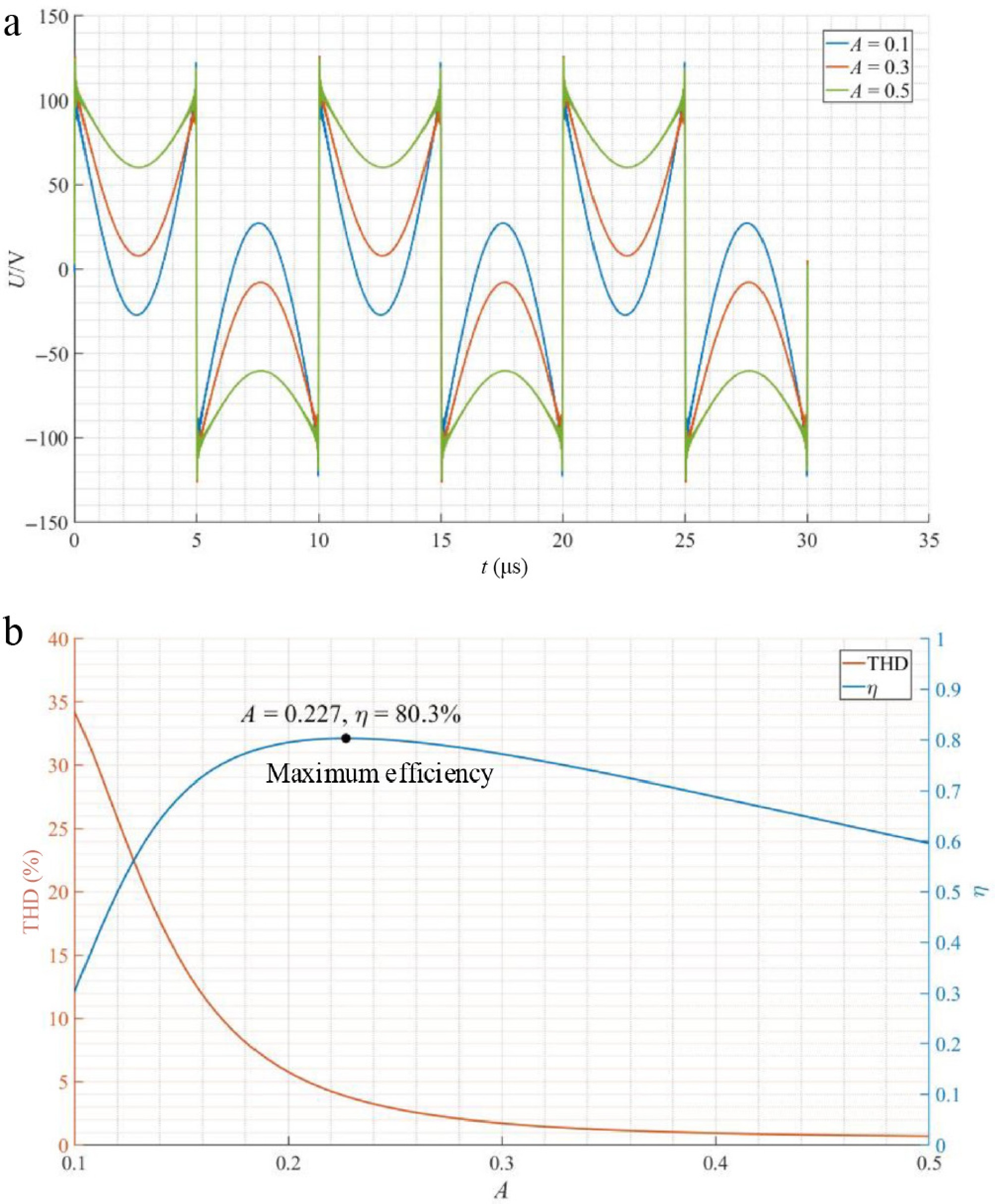
Figure 8.
Effect of parameter A on the system. (a) Output voltage of inverter under different A. (b) THD and η of the system under different A.
-
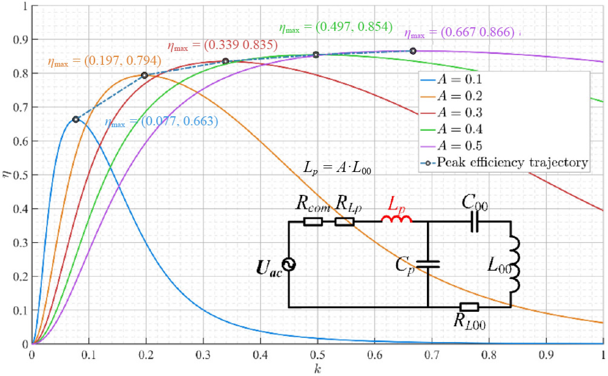
Figure 9.
Effect of coil parameters on system efficiency.
-
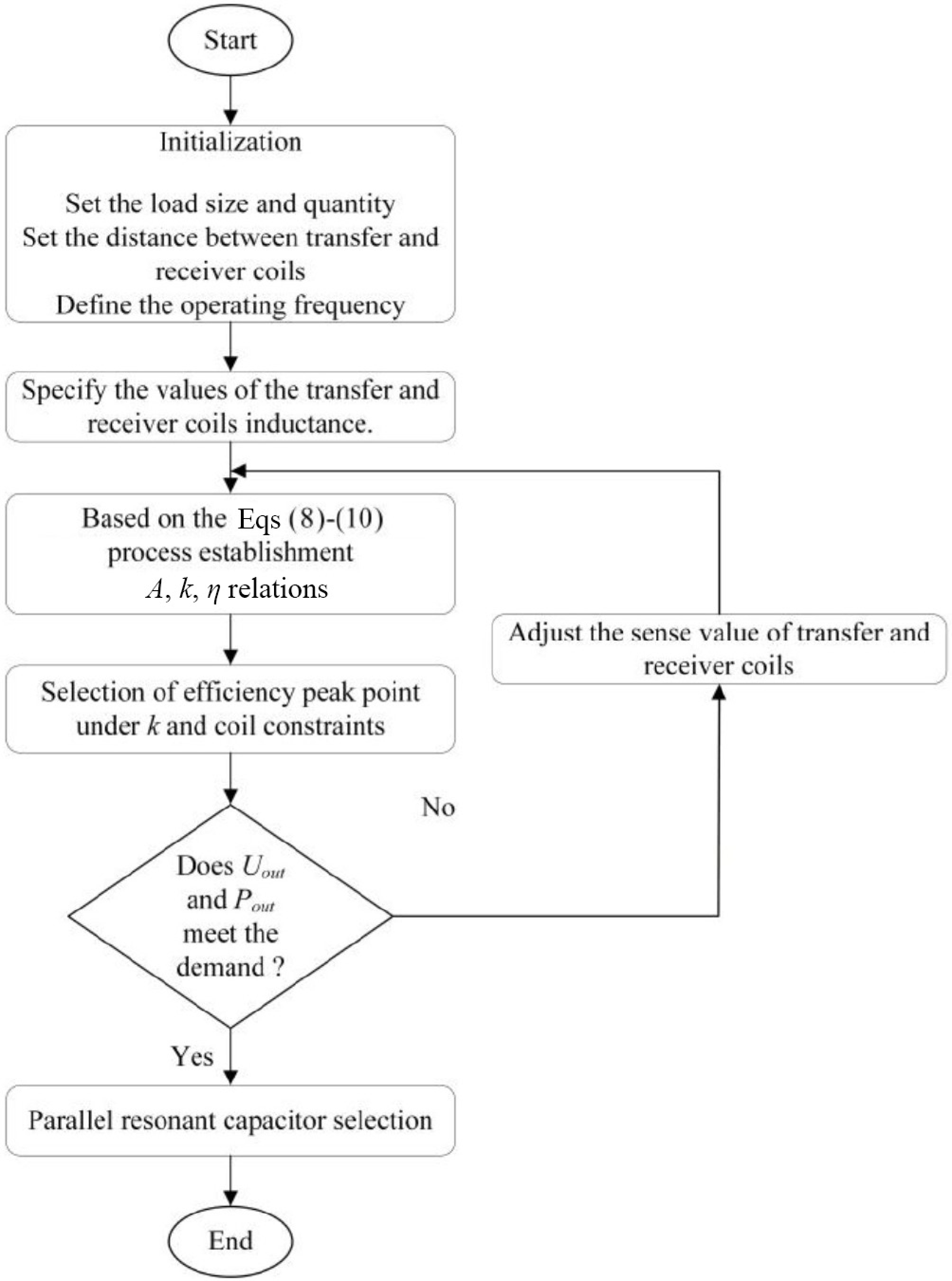
Figure 10.
Flowchart of efficiency optimization.
-
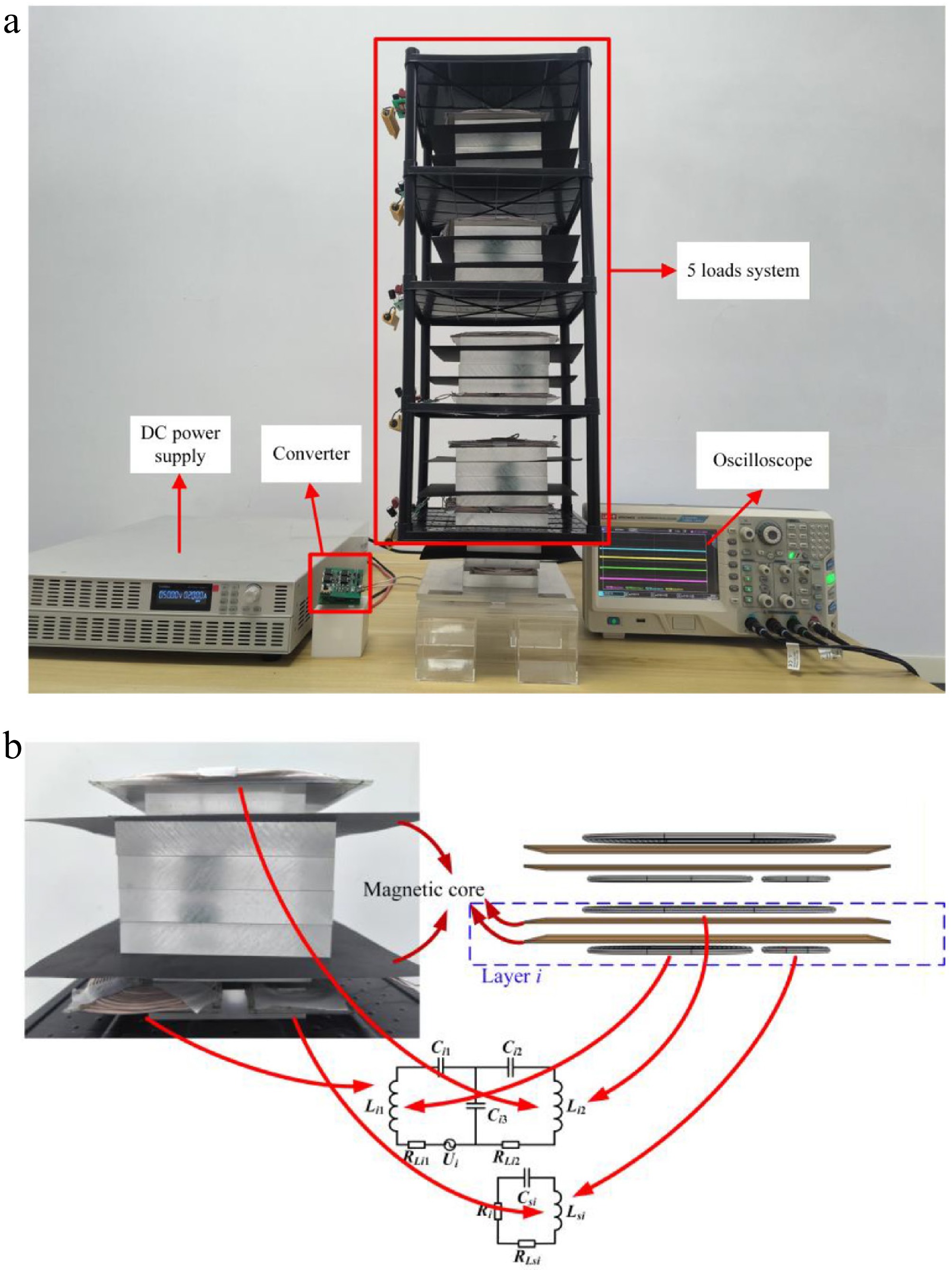
Figure 11.
Experimental platform and coil correspondence of the multi-stage WPT system. (a) Experimental platform. (b) Correspondence of coils in coupling mechanisms.
-
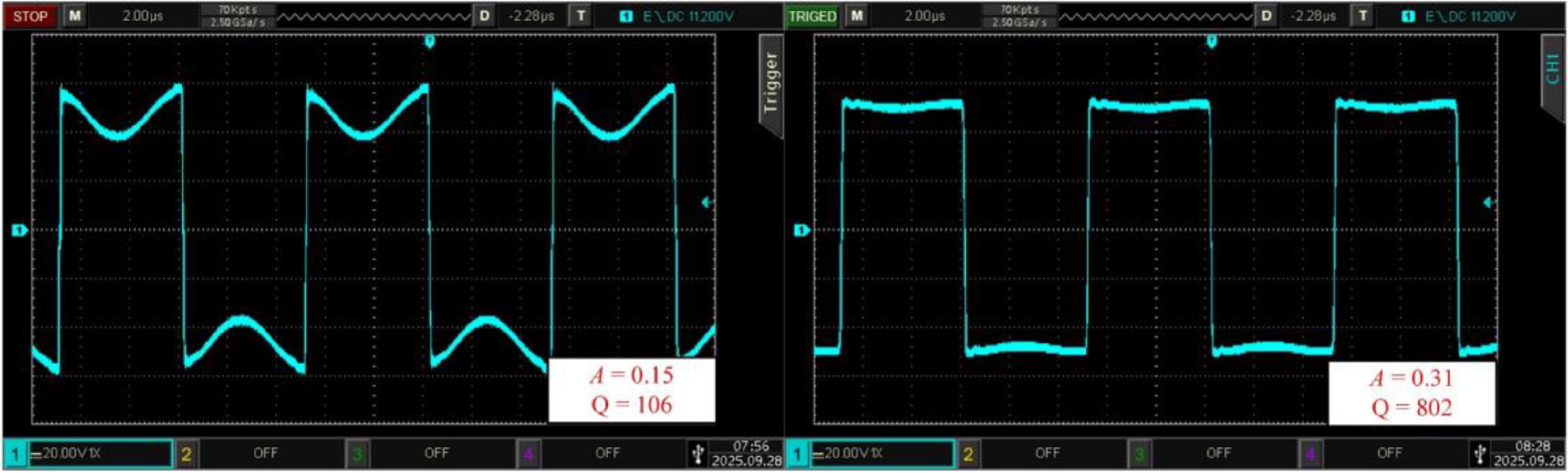
Figure 12.
Effect of A and Q on the output voltage of the inverter.
-
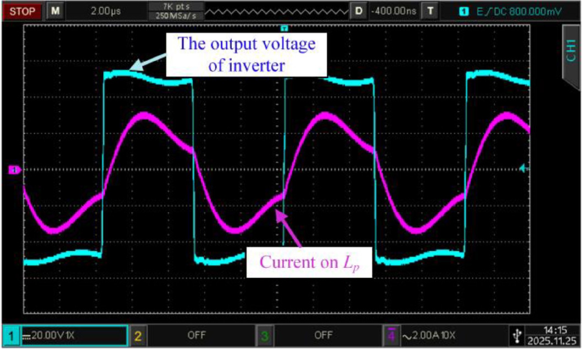
Figure 13.
Input waveform of experimental equipment.
-
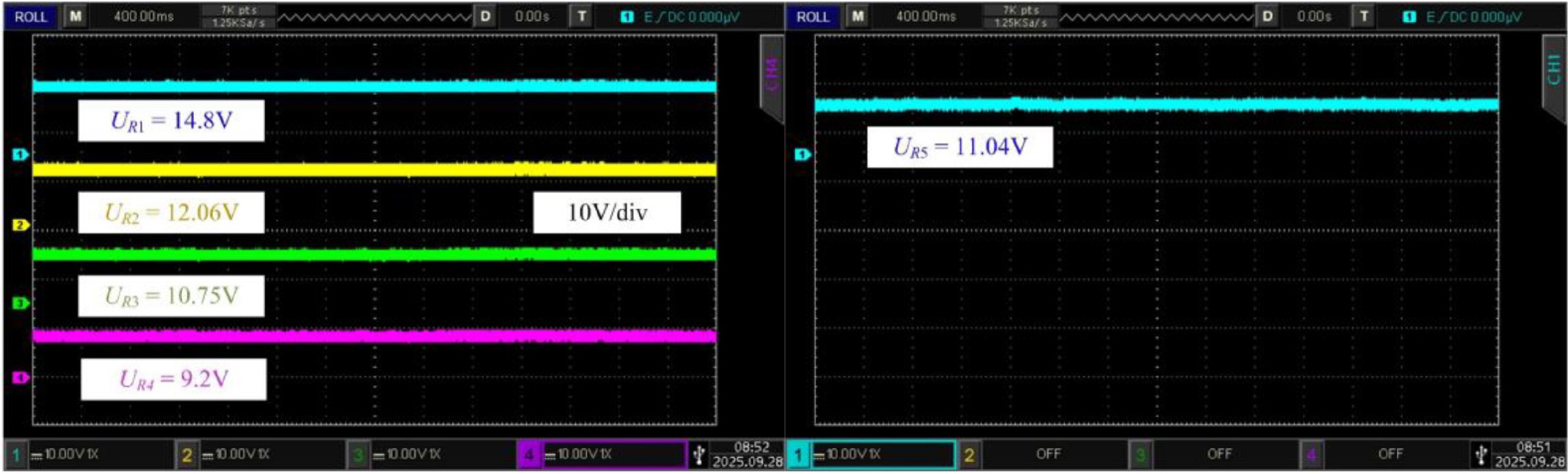
Figure 14.
Output voltage of each load.
-
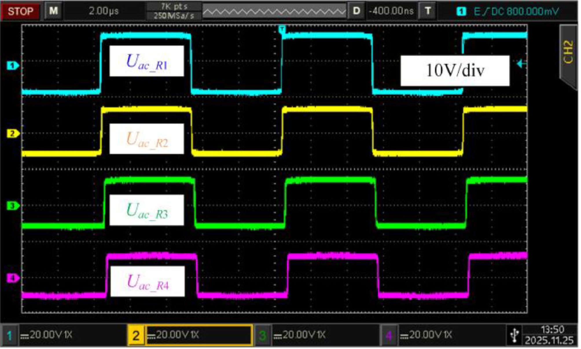
Figure 15.
The rectifier input voltage waveforms.
-
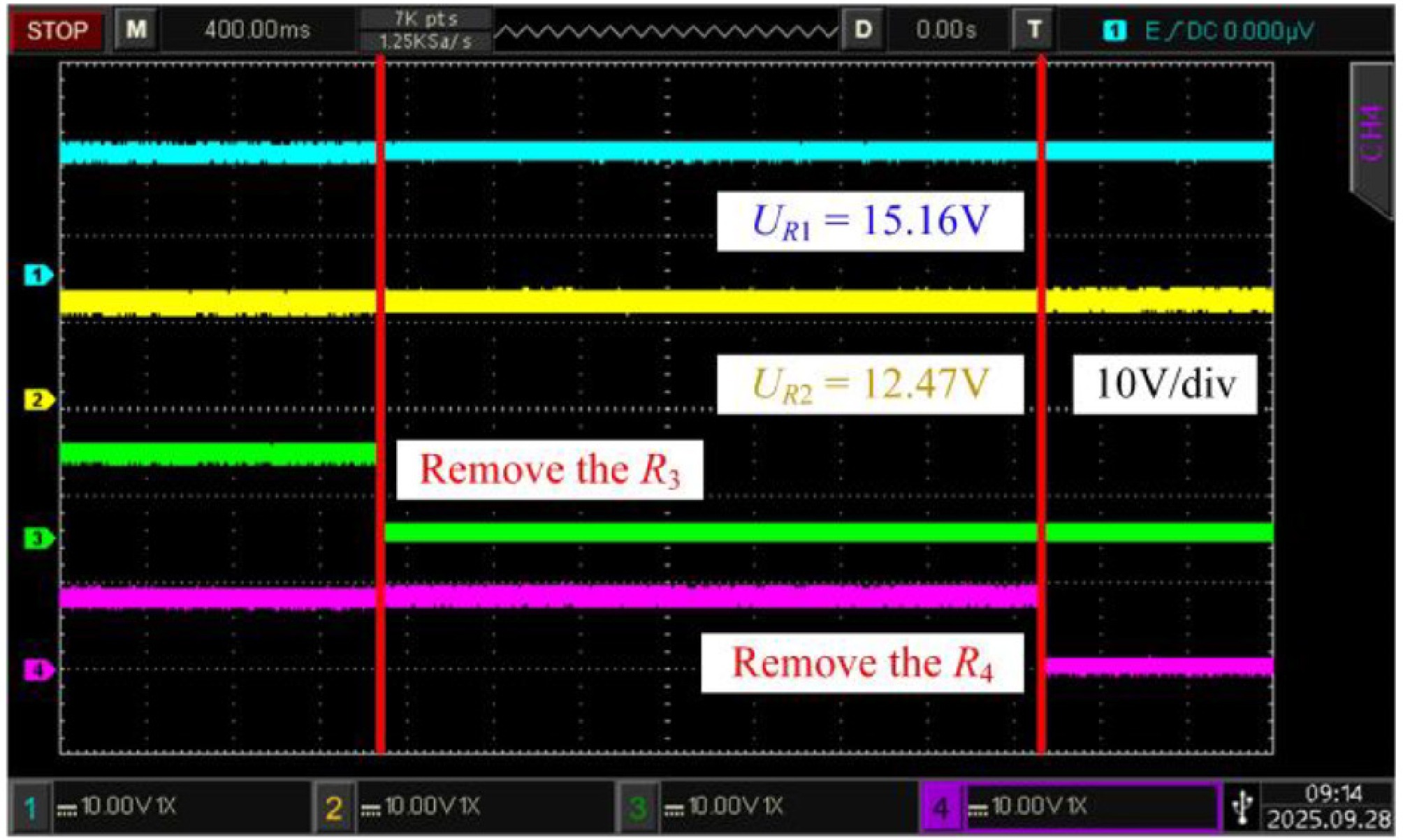
Figure 16.
The influence of load changes on the output voltage of the existing load.
-
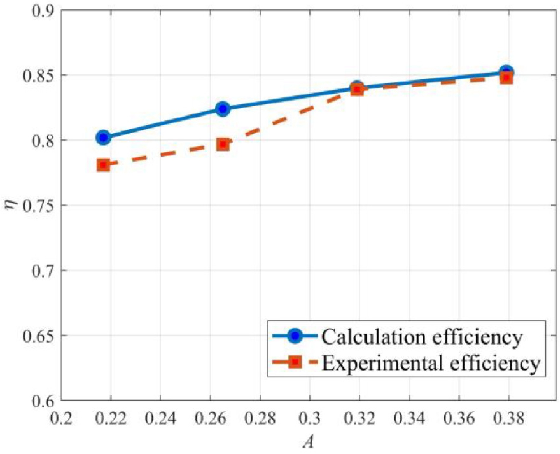
Figure 17.
Calculation efficiency and experimental efficiency under different A.
-
Parameter Value Parameter Value ki1_(i+1)1 0.0022 ki2_si 0.1012 ksi_(i+1)1 0.0014 ki2_(i+1)1 0.2167 ki1_si 0.0141 ki2_s(i+1) 0.0037 ki1_(i+1)2 0.0012 ki2_(i+1)2 0.014 Table 1.
Coupling coefficients.
-
Parameter Value Parameter Value f 100 kHz Rcom 0.1 Ω Udc 100 V RLp 0.07 Ω Lp 46 μH RL00 0.5 Ω L00 100 μH Req 5 Ω Table 2.
System parameters.
-
Parameters Values Parameters Values Udc 50 V Ci1 41.2 nF Lp 29.68 μH Ci2 31.83 nF L00 93.18 μH Ci3 99.7 nF Li1 105 μH Csi1 76.77 nF Li2 87 μH k00_11 0.27 Lsi 33 μH ki2_(i+1)1 0.21 Cp 85.3 nF ki2_si 0.15 C0 40.2 nF Ri 10 Ω Table 3.
System parameters.
Figures
(17)
Tables
(3)