-
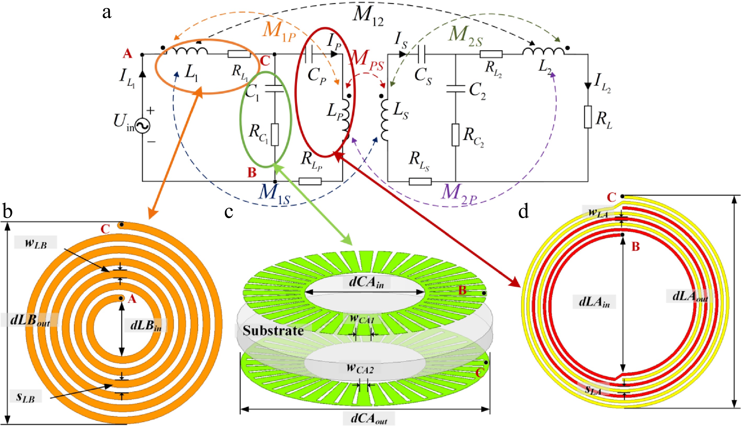
Figure 1.
(a) Equivalent circuit of IPT system with double-sided SR LCC coils. (b) Main coil. (c) Compensation coil. (d) Parallel capacitor.
-
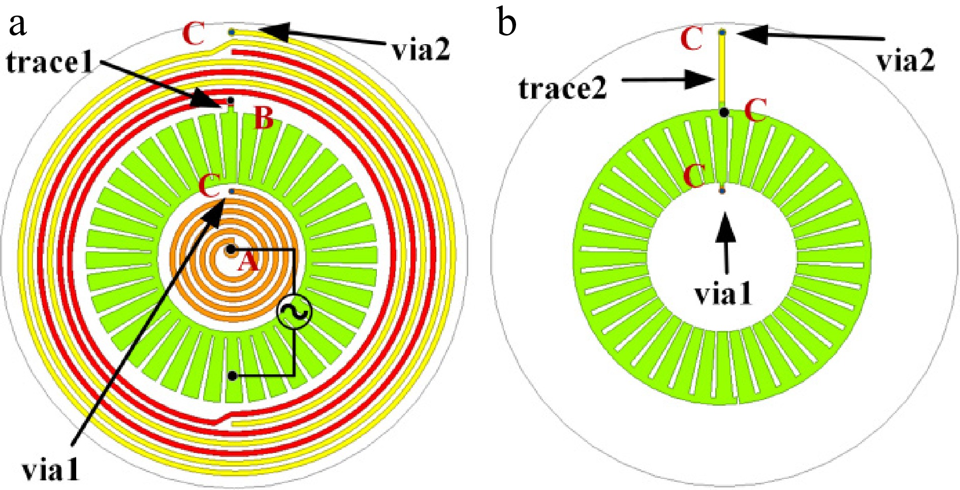
Figure 2.
The SR LCC coil structure. (a) Top view. (b) Bottom view.
-
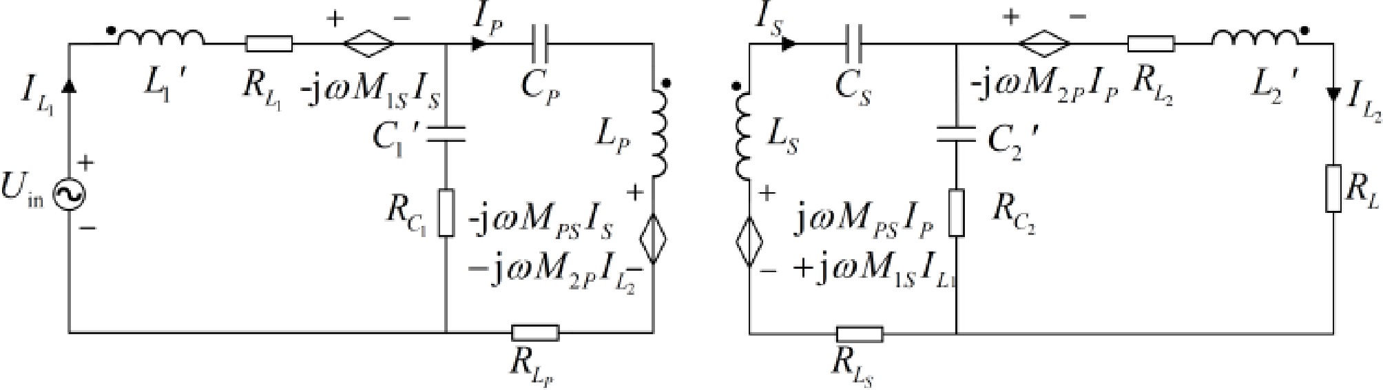
Figure 3.
IPT system with double-sided self-resonant LCC coils after decoupling.
-
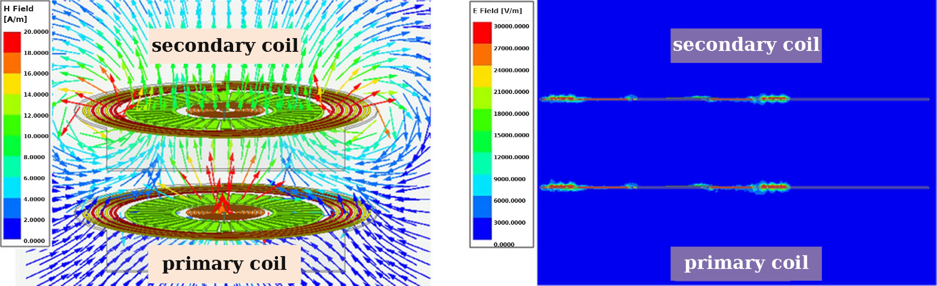
Figure 4.
Field distribution of the coils. (a) Magnetic field distribution. (b) Electric field distribution.
-
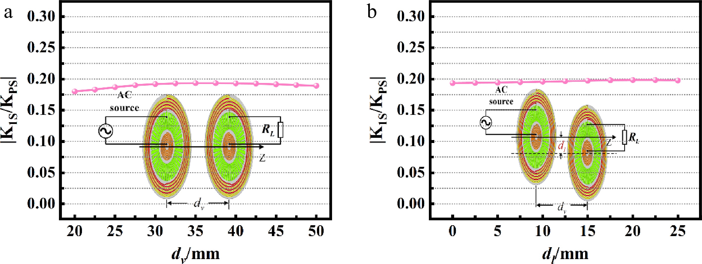
Figure 5.
The variation curve of K1S/KPS. (a)
$ {d}_{v} $ $ {d}_{l} $ $ {d}_{v} $ -
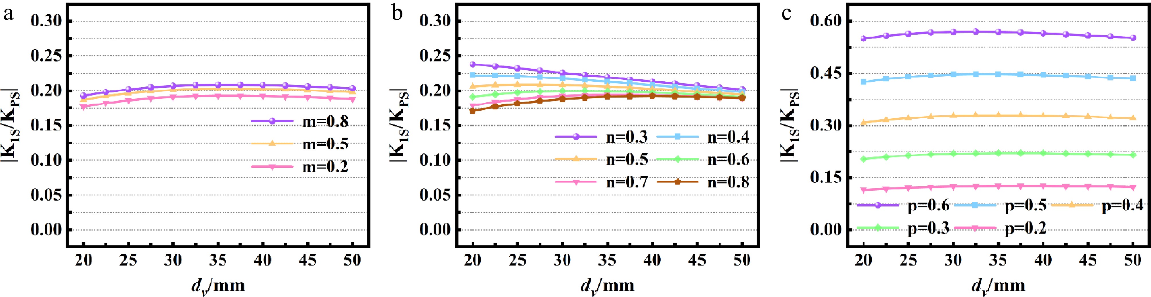
Figure 6.
The variation curve of K1S/KPS with changes in dv when (a) dLBin changes; (b) dLCin changes; and (c) dLBout changes.
-
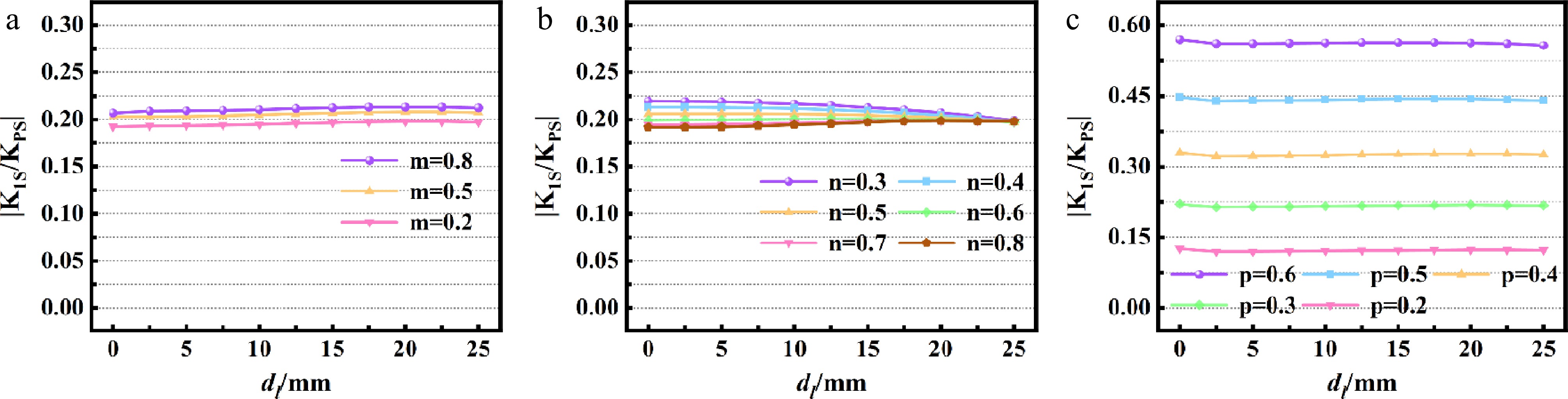
Figure 7.
The variation curve of K1S/KPS with changes in dl at a fixed dv of 35 mm when (a) dLBin changes; (b) dLAin changes; and (c) dLBout changes.
-
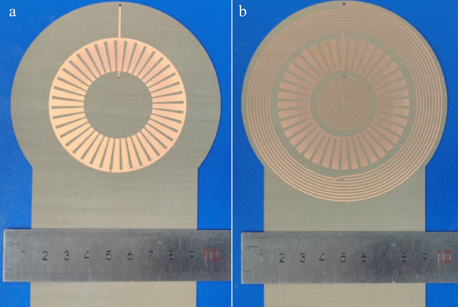
Figure 8.
Fabricated coils. (a) Top view of the LCC SR coil. (b) Bottom view of the LCC SR coil.
-
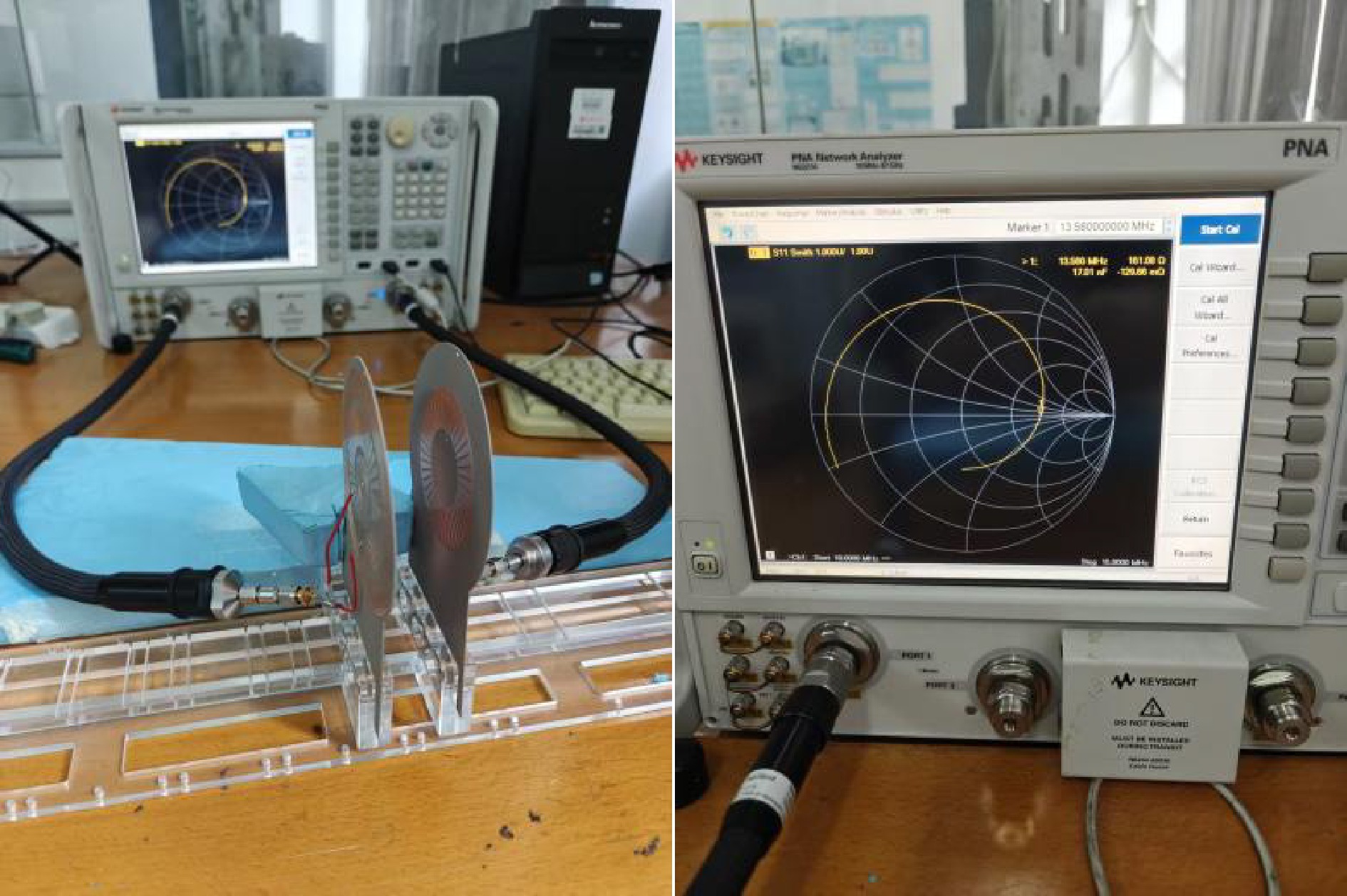
Figure 9.
Experimental setups of the double sided SR LCC coils.
-
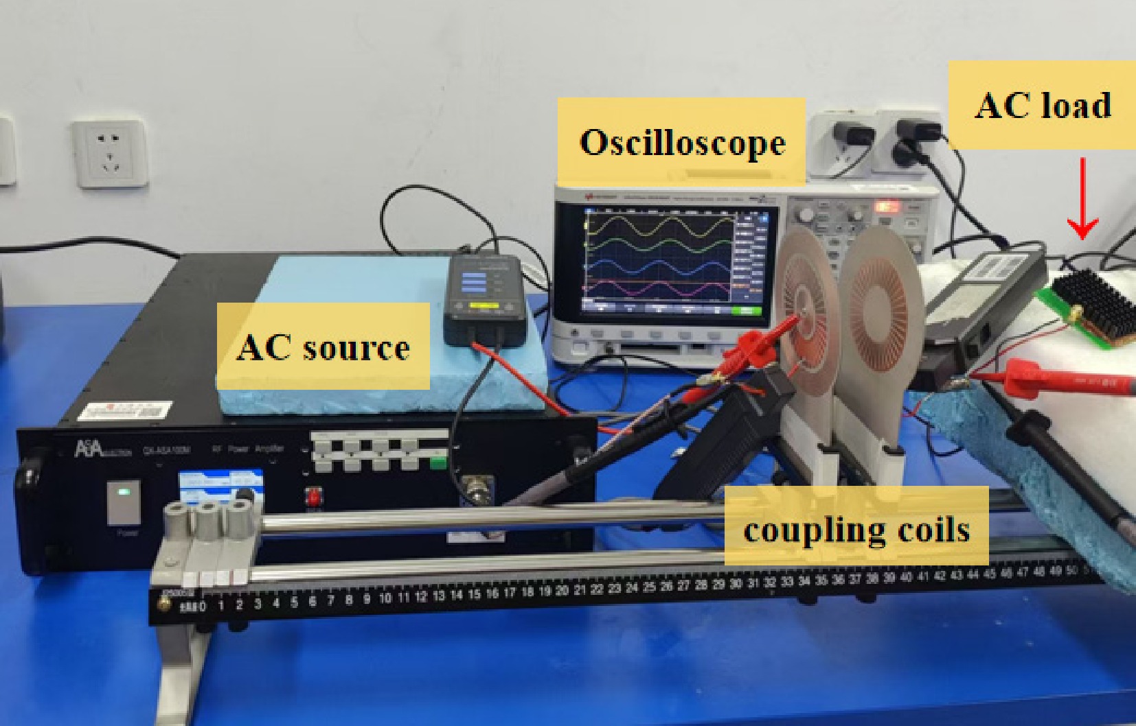
Figure 10.
AC-AC experimental setup of the SR coil IPT system with LCC-LCC compensation characteristics.
-
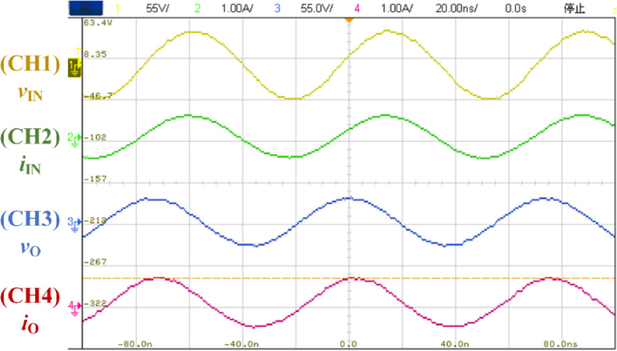
Figure 11.
Measured waveforms on the oscilloscope of the proposed IPT system with an AC load of 50 Ω.
-
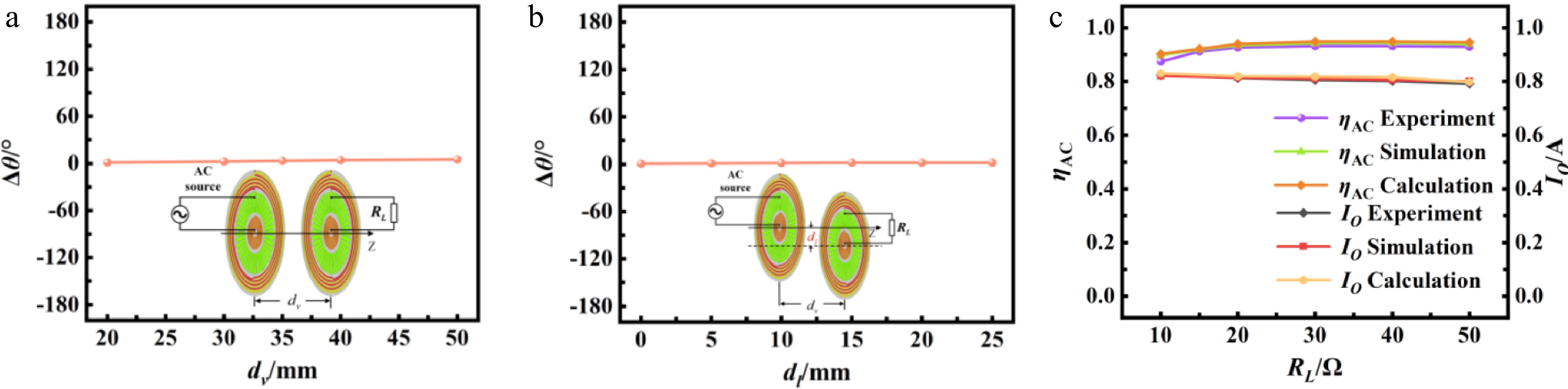
Figure 12.
(a)
$ \Delta \theta $ $ {d}_{v} $ $ \Delta \theta $ $ {d}_{l} $ $ {d}_{v} $ $ {R}_{L} $ -
Parameter Simulated value Measured value Main inductor LP, LS 4.52 μH 4.46 μH Series inductor L1, L2 0.765 μH 0.74 μH Parallel capacitor C1, C2 155.42 pF 159.6 pF Series capacitor CP, CS 37.9 pF 40.4 pF Primary coupling coefficient KPS 0.186 N/A Intra-side coupling coefficient K1P, K2S −0.08 N/A Cross-coupling coefficient K1S, K2P −0.036 N/A Minor coupling coefficient K12 0.018 N/A Table 1.
Equivalent circuit parameters of double-sided LCC SR coil IPT system.
-
Dimensional parameter Description Value dLAin Inner diameter of LA 71 mm dLAout Outer diameter of LA 100 mm NLA Turn numbers of LA 5 wLA Winding width of LA 0.83 mm sLA Winding space of LA 1.52 mm dCAin Inner diameter of CA 33 mm dCAout Outer diameter of CA 67 mm wCA1 Inner width of each tooth of CA 2.22 mm wCA2 Outer width of each tooth of CA 3.8 mm dLBin Inner diameter of LB 6.525 mm dLBout Outer diameter of LB 28 mm NLB Turn numbers of LB 7 wLB Winding width of LB 0.85 mm sLB Winding space of LB 1.45 mm Table 2.
Dimensional parameters of coils.
-
Structural components Loss (Ω) Q LCC SR main coil LA 1.8 214 Compensation coil LB 0.4 163 Parallel capacitor CA 0.2 377.6 Table 3.
Optimized Q and associated losses of double-sided LCC SR coil IPT system.
Figures
(12)
Tables
(3)