-
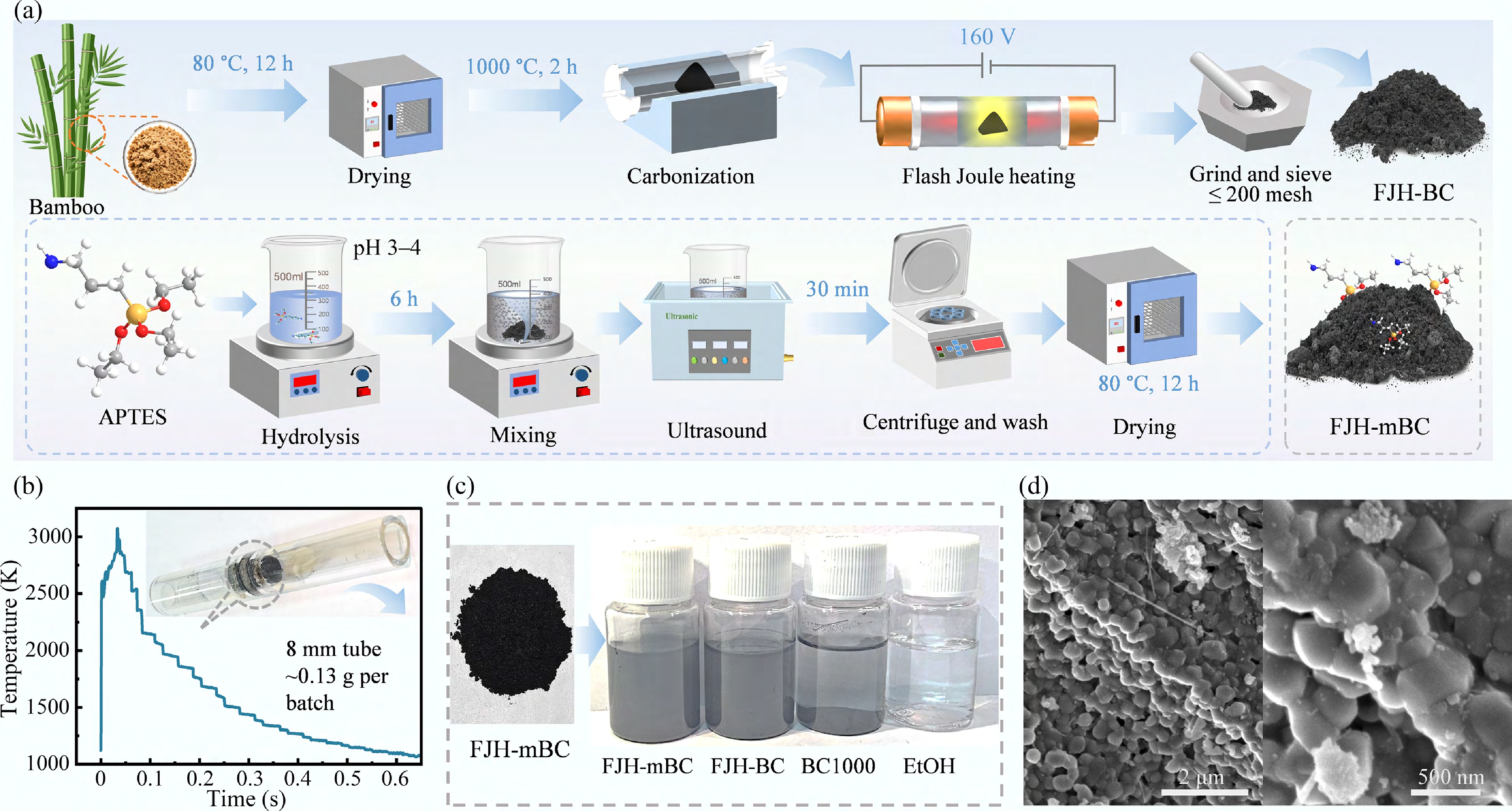
Figure 1.
Fabrication process of FJH-mBC. (a) Schematic illustration of the synthesis route; (b) Joule heating temperature profile with inset photograph; (c) morphology and dispersion comparison; and (d) SEM images of FJH-mBC.
-
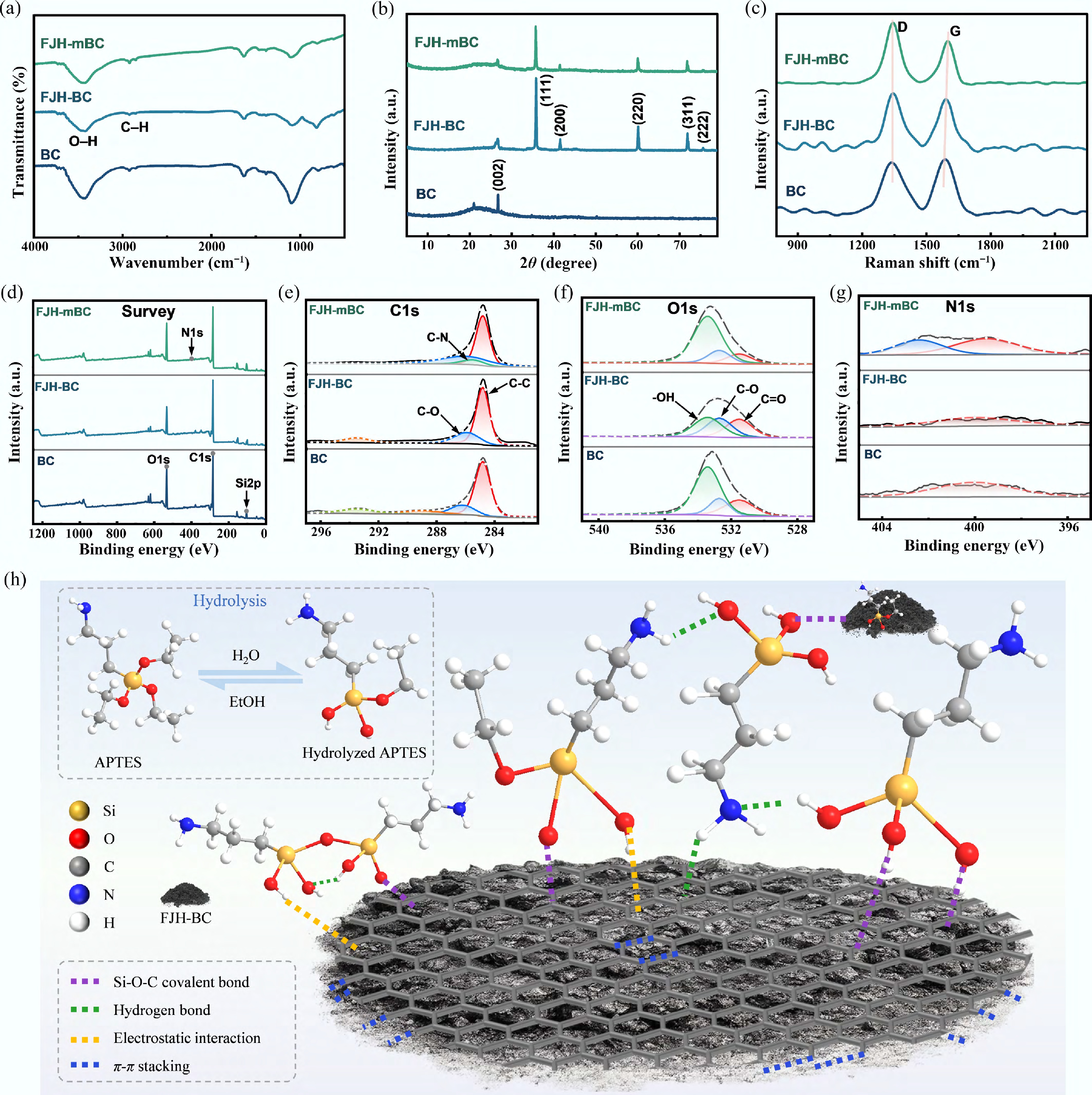
Figure 2.
Structural characterization and interaction mechanism of FJH-mBC. (a) FTIR spectra; (b) XRD patterns; (c) Raman spectra; (d) XPS survey spectra and corresponding high-resolution spectra of (e) C1s, (f) O1s, and (g) N1s; and (h) schematic illustration of interfacial interactions.
-

Figure 3.
Fabrication, structural characterization, and interfacial interactions of PLB composites. (a) Schematic illustration of the preparation process; (b) FTIR spectra; (c) XRD patterns; and (d) schematic illustration of interfacial interactions.
-
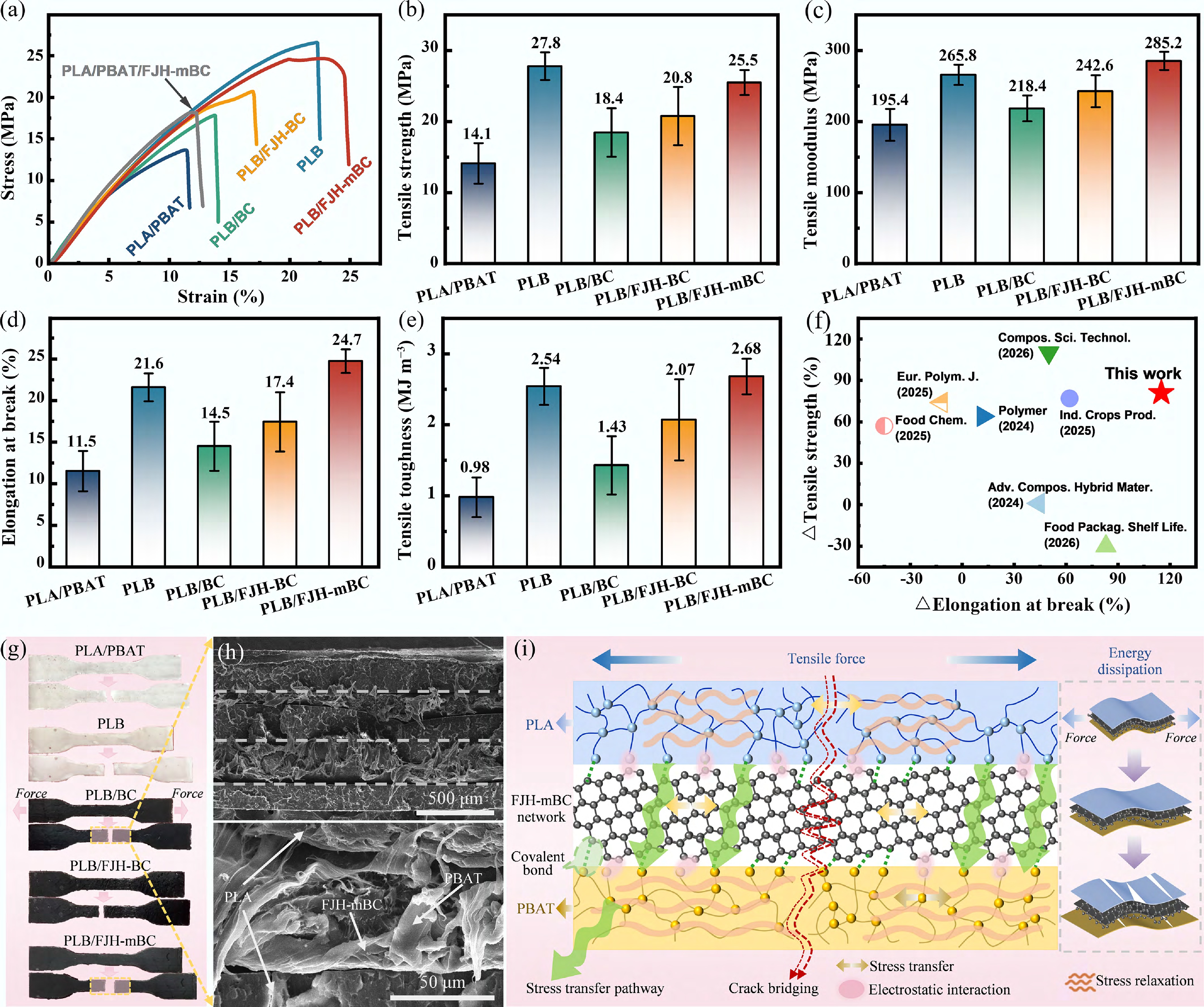
Figure 4.
Mechanical performance and toughening mechanism of PLB composites. (a) Stress–strain curves; (b) tensile strength; (c) tensile modulus; (d) elongation at break; (e) toughness; (f) comparison with reported materials; (g) fracture photographs; (h) SEM images; and (i) schematic illustration of the toughening mechanism.
-
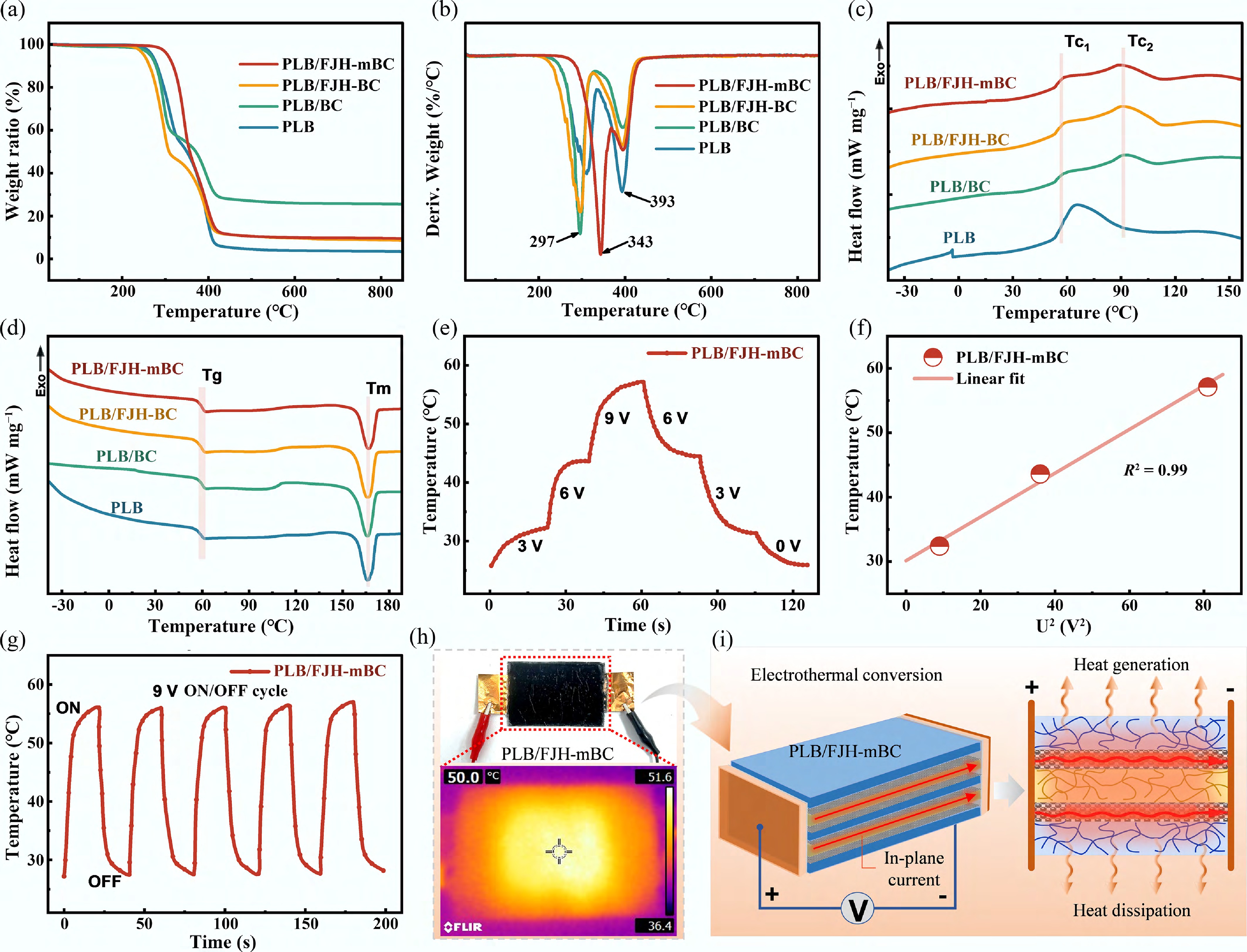
Figure 5.
Thermal and electrothermal properties of PLB composites. (a) TG curves; (b) DTG curves; (c) DSC cooling curves; (d) DSC heating curves; (e) temperature evolution curves under different applied voltages; (f) linear fitting of surface temperature vs U2; (g) electrothermal cycling stability; (h) IR image; and (i) schematic illustration of the Joule heating mechanism.
-
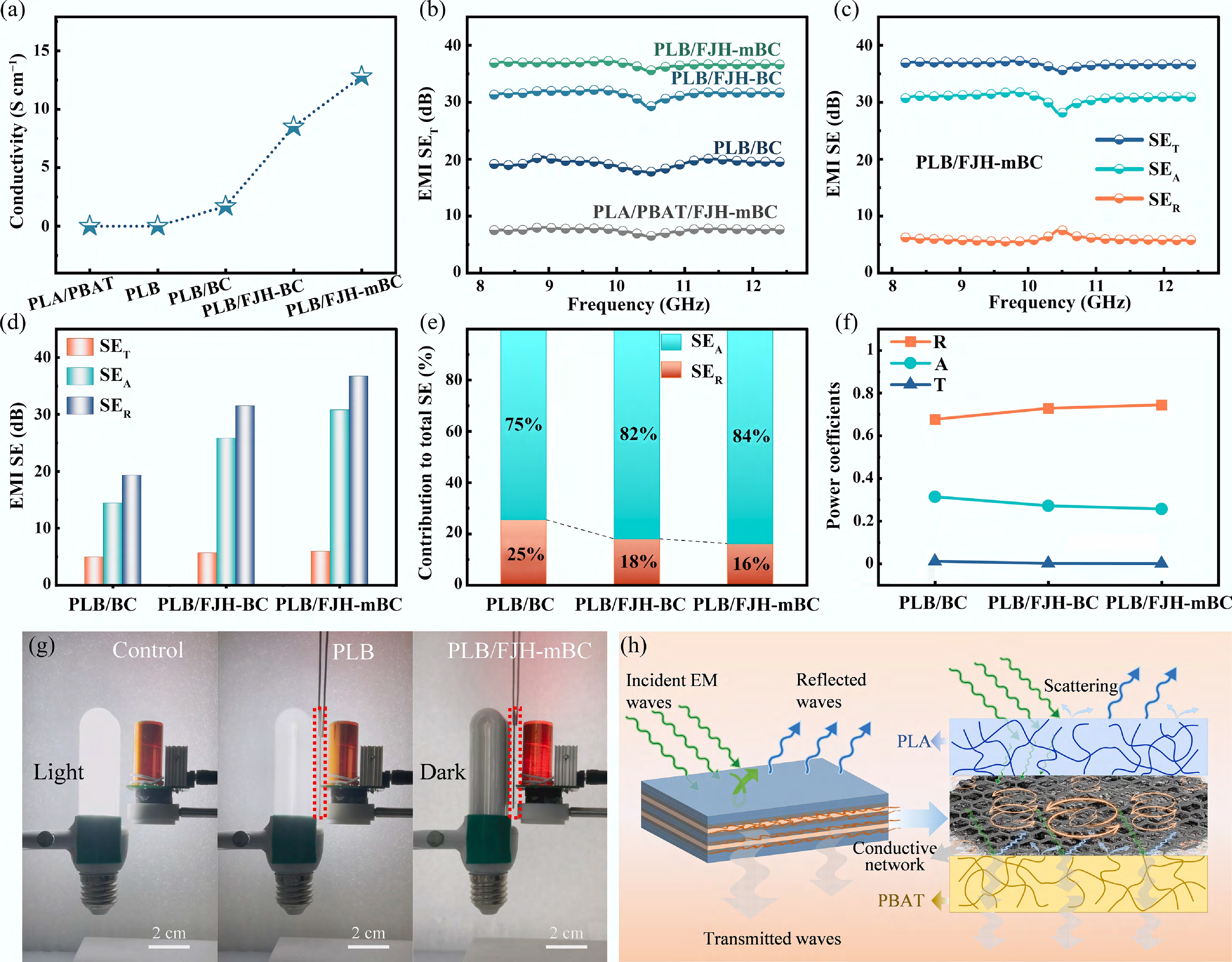
Figure 6.
Electrical conductivity, EMI shielding performance, and mechanism of PLB composites. (a) Conductivity; (b) EMI SE of different samples; (c) SE components of the optimal sample; (d) SE decomposition; (e) contribution to total SE; (f) power coefficients; (g) EMI shielding demonstration; and (h) shielding mechanism illustration.
Figures
(6)
Tables
(0)