-
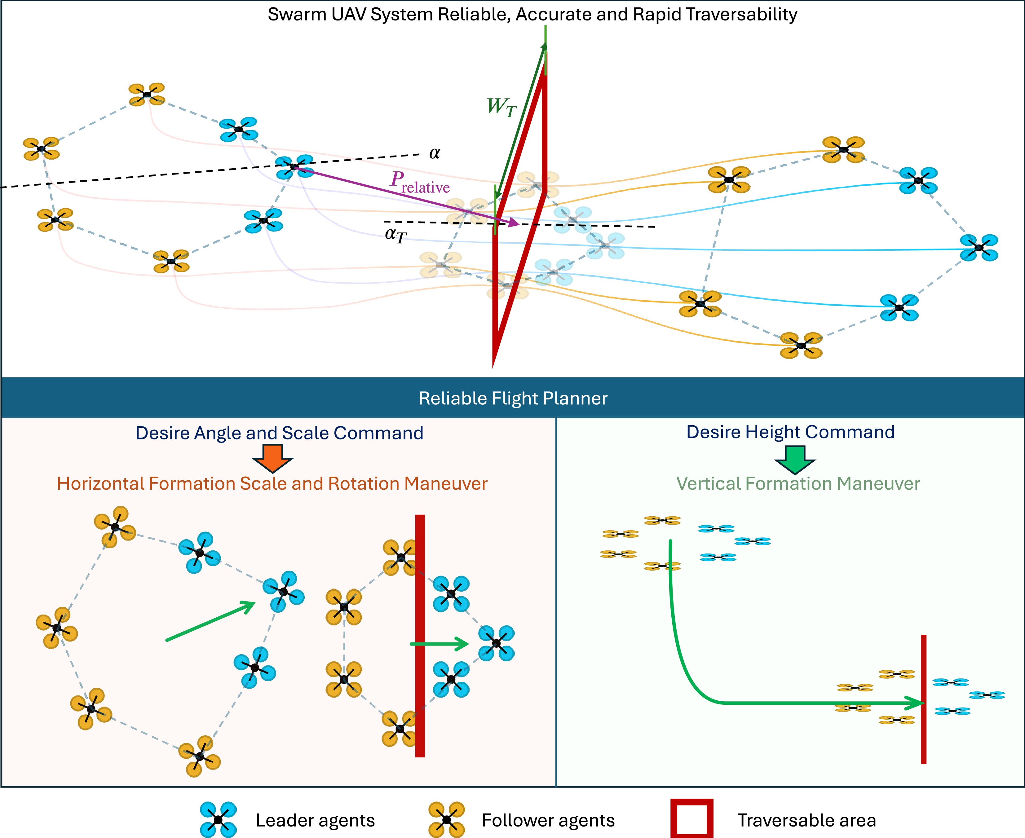
Figure 1.
Diagram of a UAV swarm traversing problem.
-
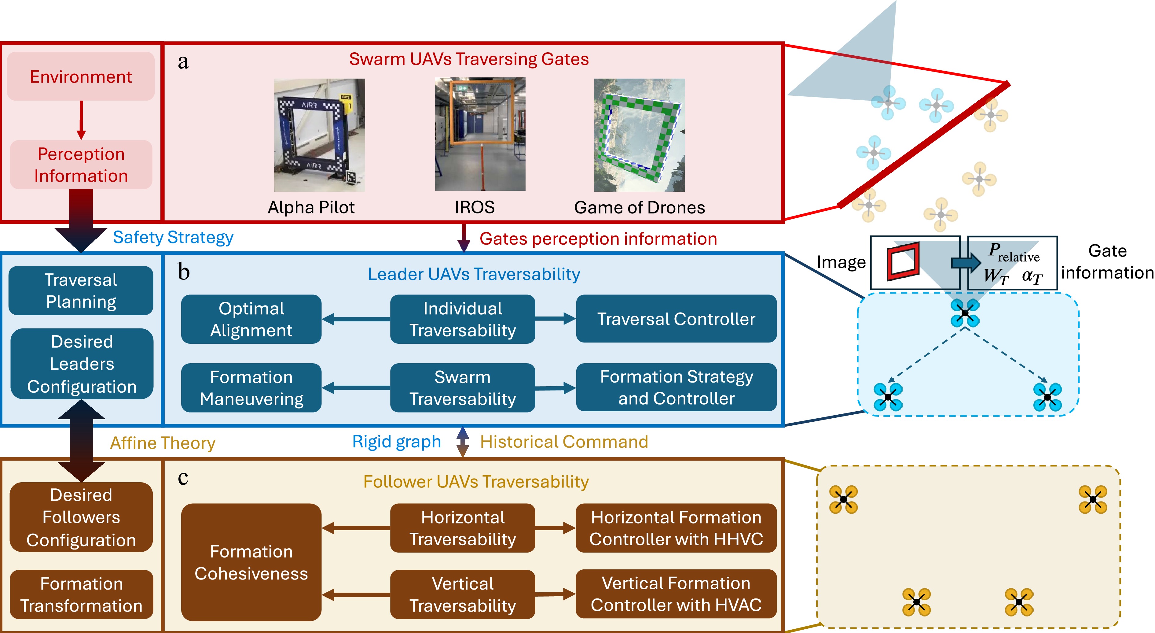
Figure 2.
Diagram of a UAV swarm traversing framework.
-
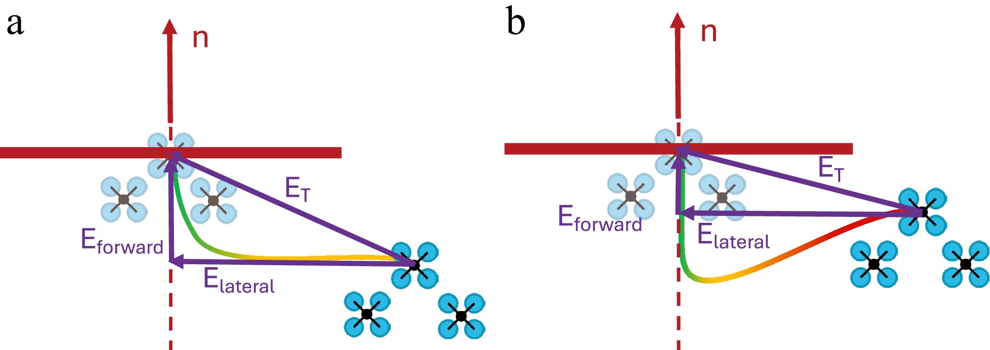
Figure 3.
Diagram of leaders trajectory planning under normal and dangerous cases. (a) Trajectory planning under normal cases. (b) Trajectory planning when the leaders are seriously close to the constrained area but not aligned with the center of the area.
-
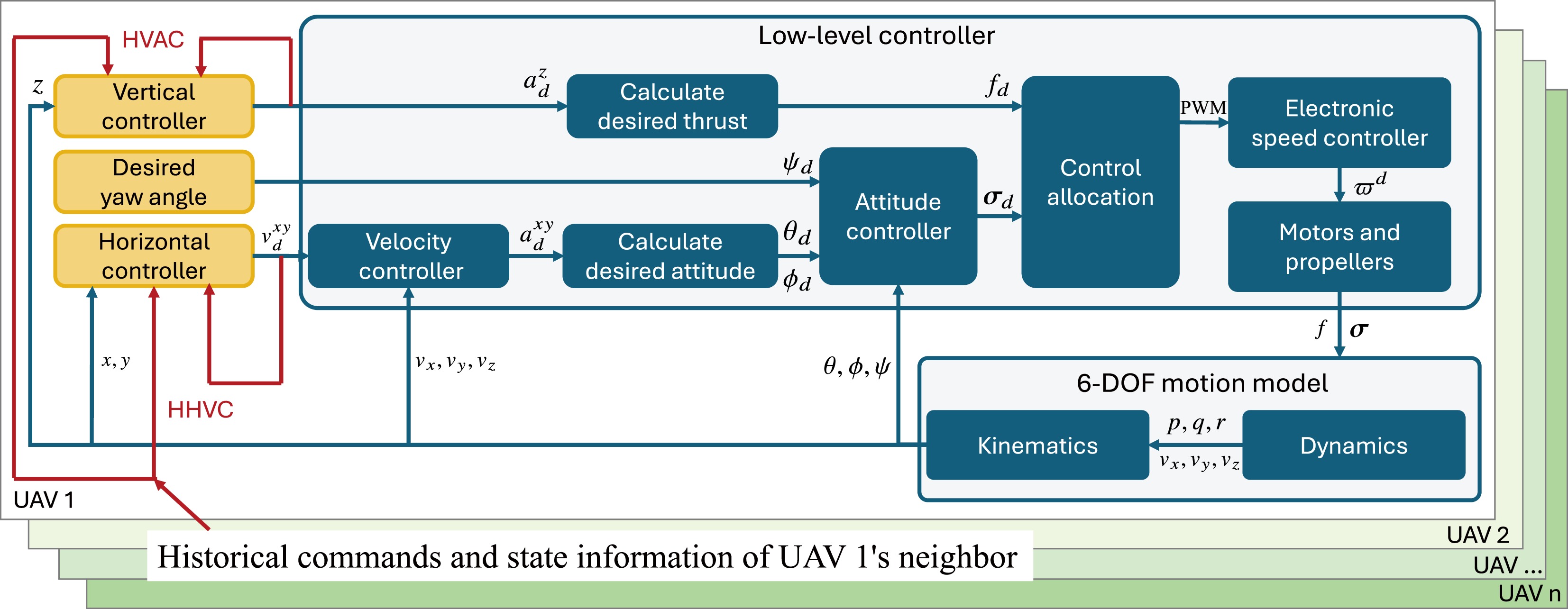
Figure 4.
Designed vertical and horizontal controllers applied to the quadrotor with a low-level controller. Note that the paper is not concerned with yaw planning, and we set the desired yaw angle to zero.
-
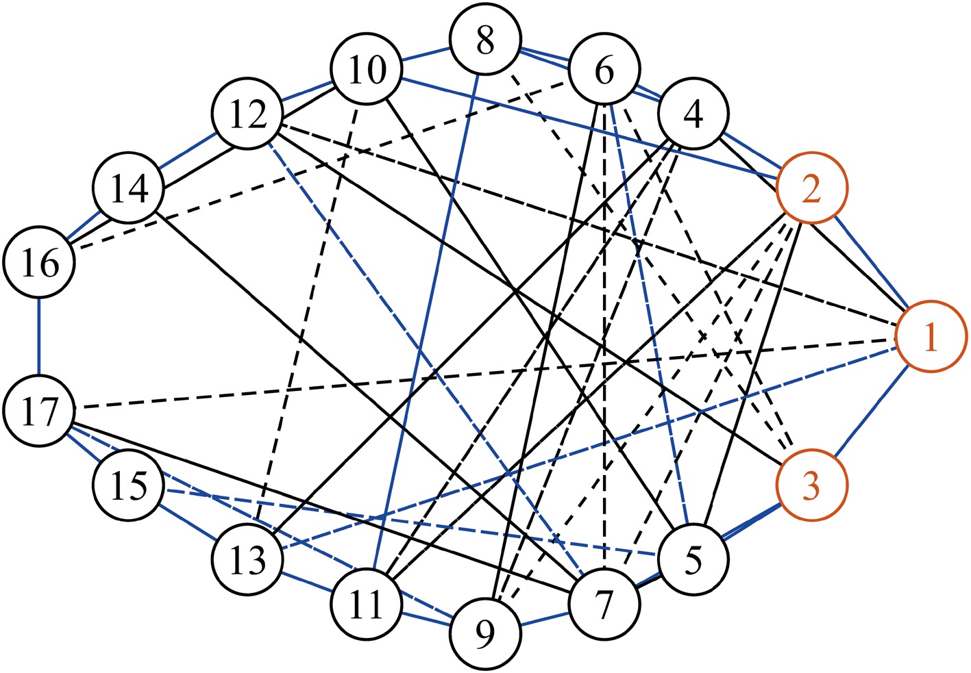
Figure 5.
The nominal framework in simulation. Orange nodes indicate leaders and white nodes indicate followers. Solid lines represent positive stress while dashed lines denote negative stress. All lines are used for communication in the original network (47 edges), and blue lines are used in the line-type network (24 edges).
$ P(r) $ -
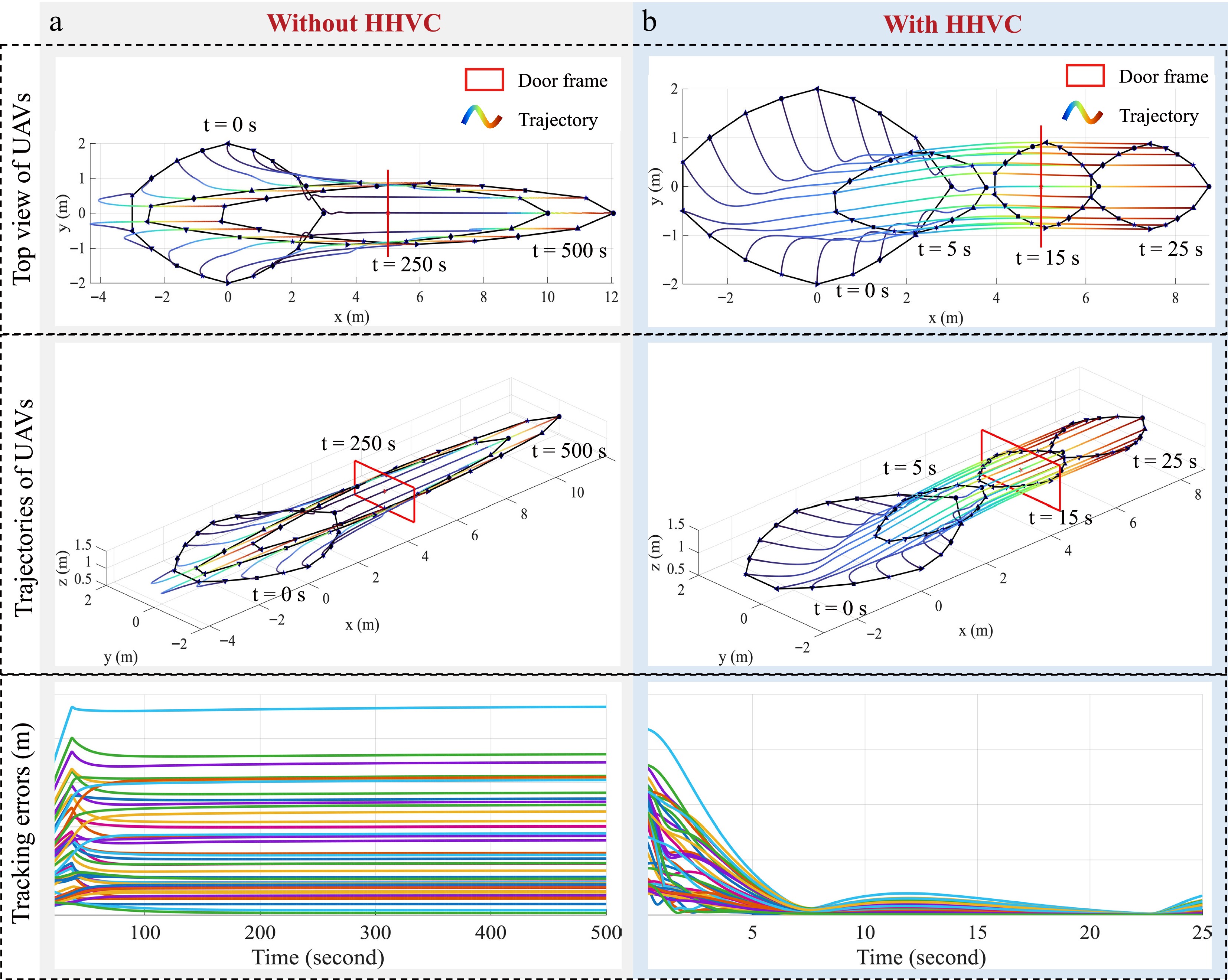
Figure 6.
Simulation case 1. (a) Top view, trajectories, and error dynamics without HHVC in position control. (b) Top view, trajectories, and error dynamics with HHVC in position control.
-
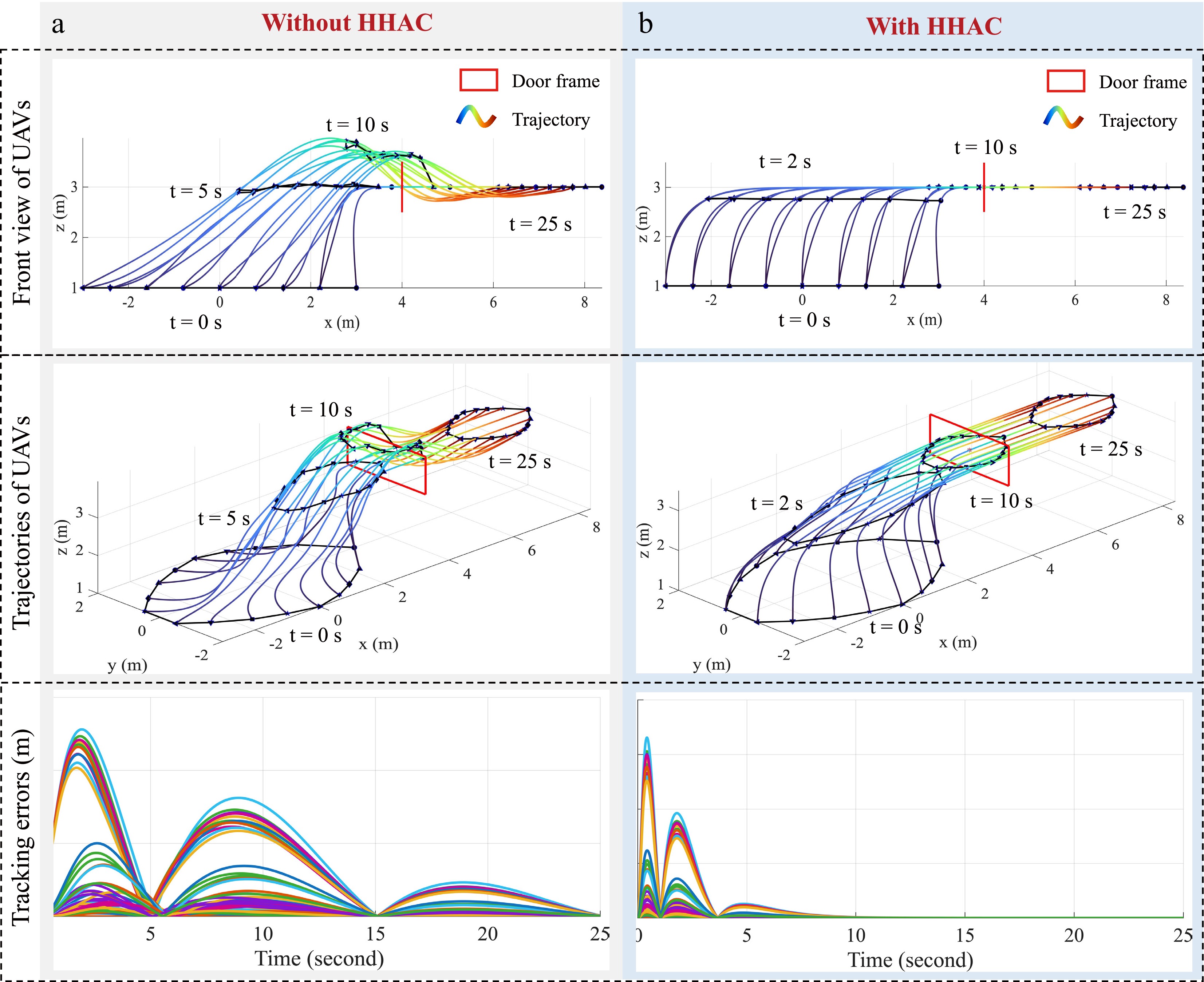
Figure 7.
Simulation case 2. (a) Front view, trajectories, and error dynamics without HHAC in altitude control. (b) Front view, trajectories, and error dynamics with HHAC in altitude control.
-
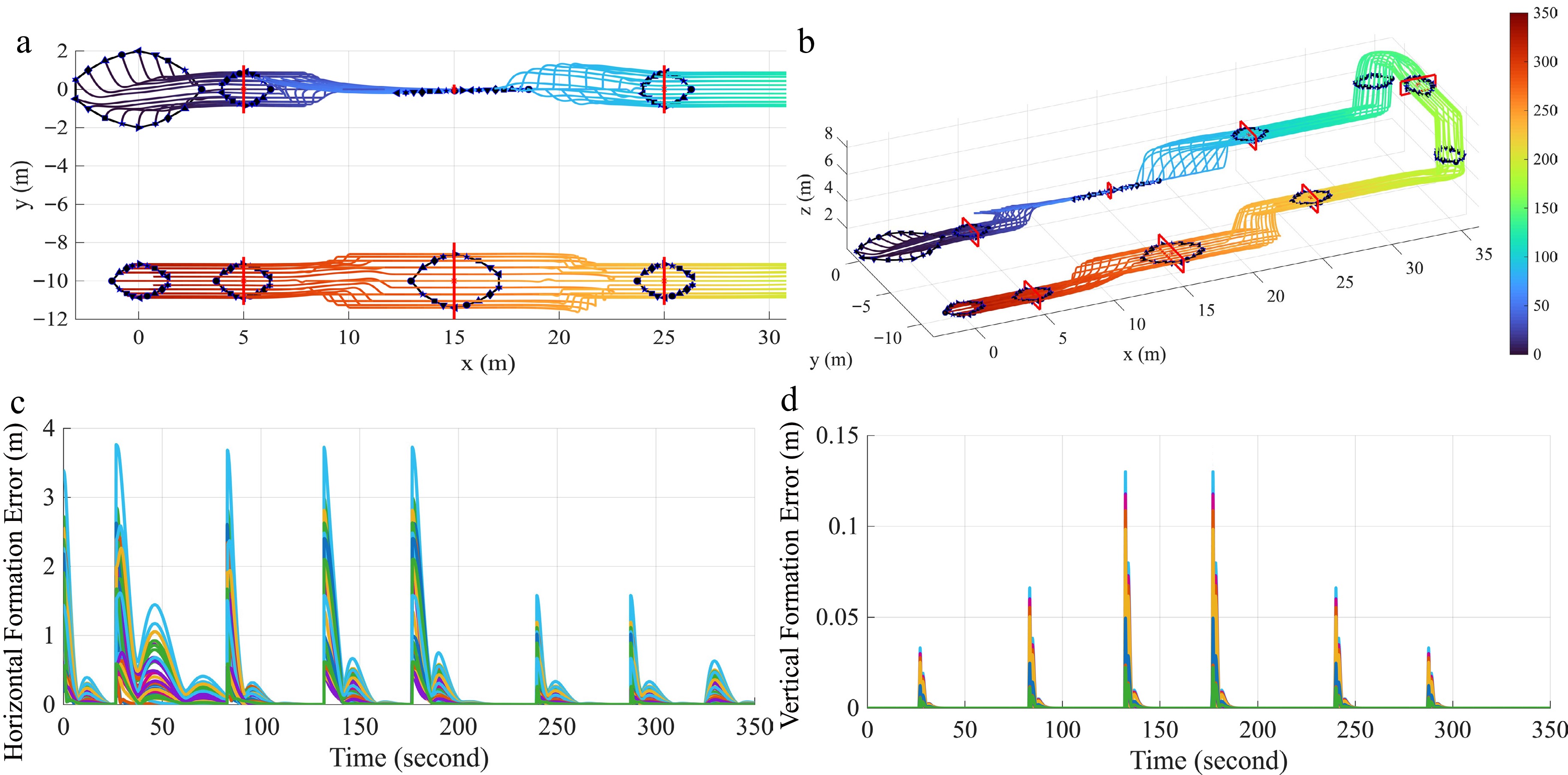
Figure 8.
Simulation case 3. (a) Top and 3D views of quadrotor swarms trajectories; (b) formation tracking errors in position control; (c) formation tracking errors in altitude horizontal control; (d) formation tracking errors in altitude control.
-
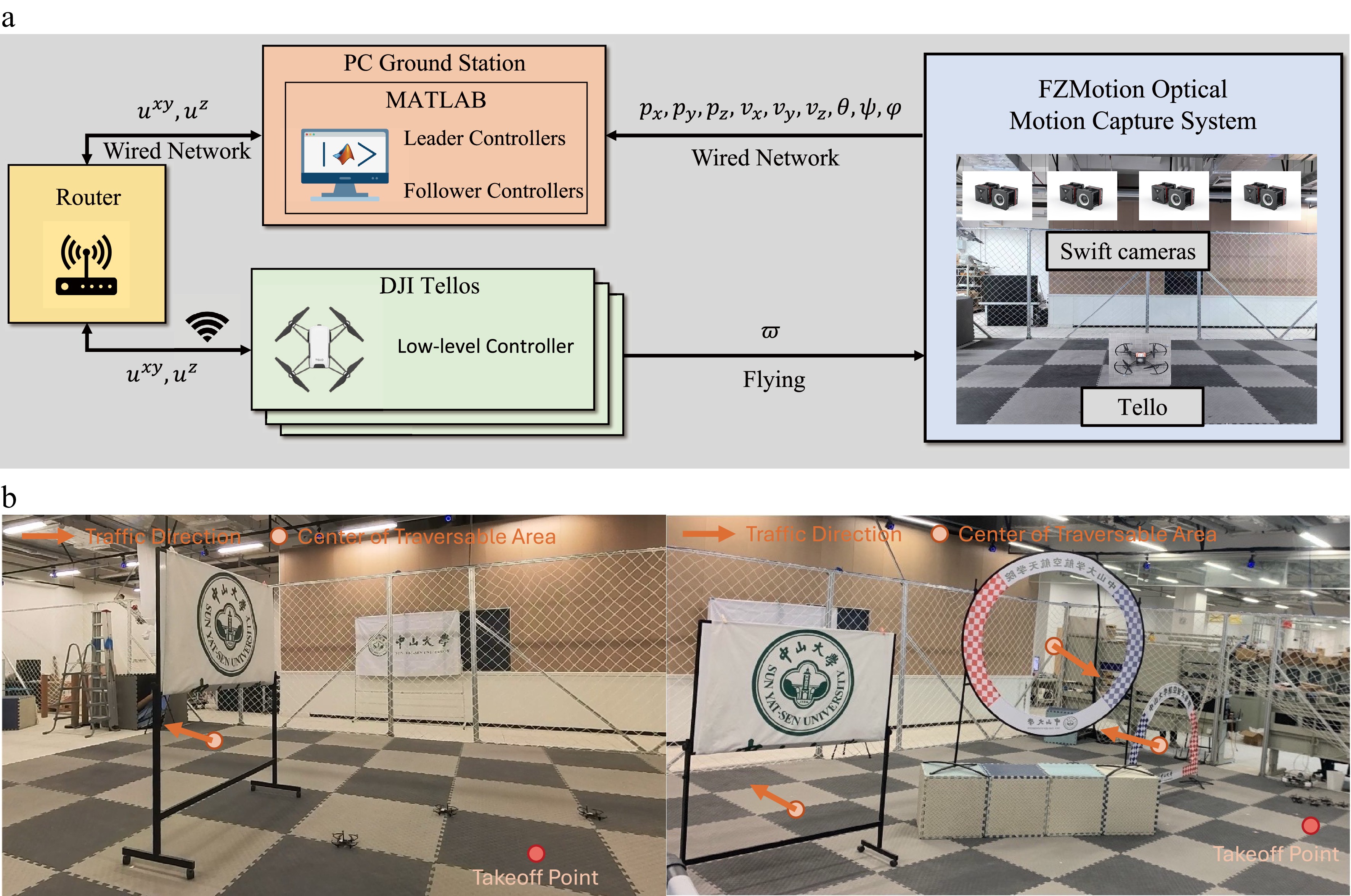
Figure 9.
Experimental setup. (a) Diagram of communication topology, signal flow and experiment platform. Note that our proposed distributed algorithm was experimentally verified using a centralized communication infrastructure. (b) Snapshots of experiments scenario setup. The Left one is for the experiment 1, and the right one is for the experiment 2.
-
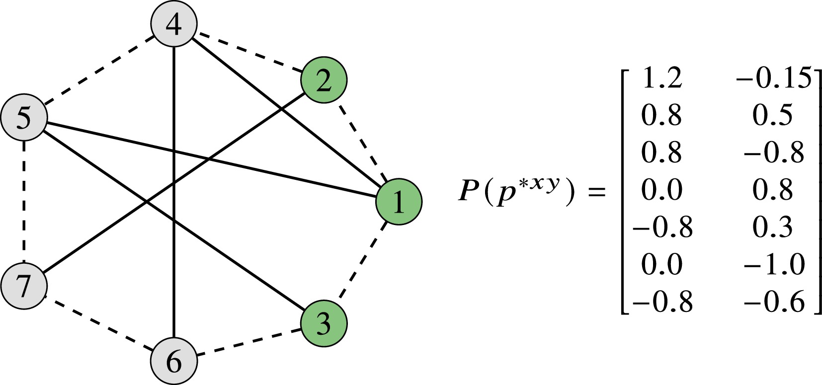
Figure 10.
Nominal formation based on an undirected graph in the experiment. Green nodes represent the leaders.
$ P(p^{*xy}) $ -
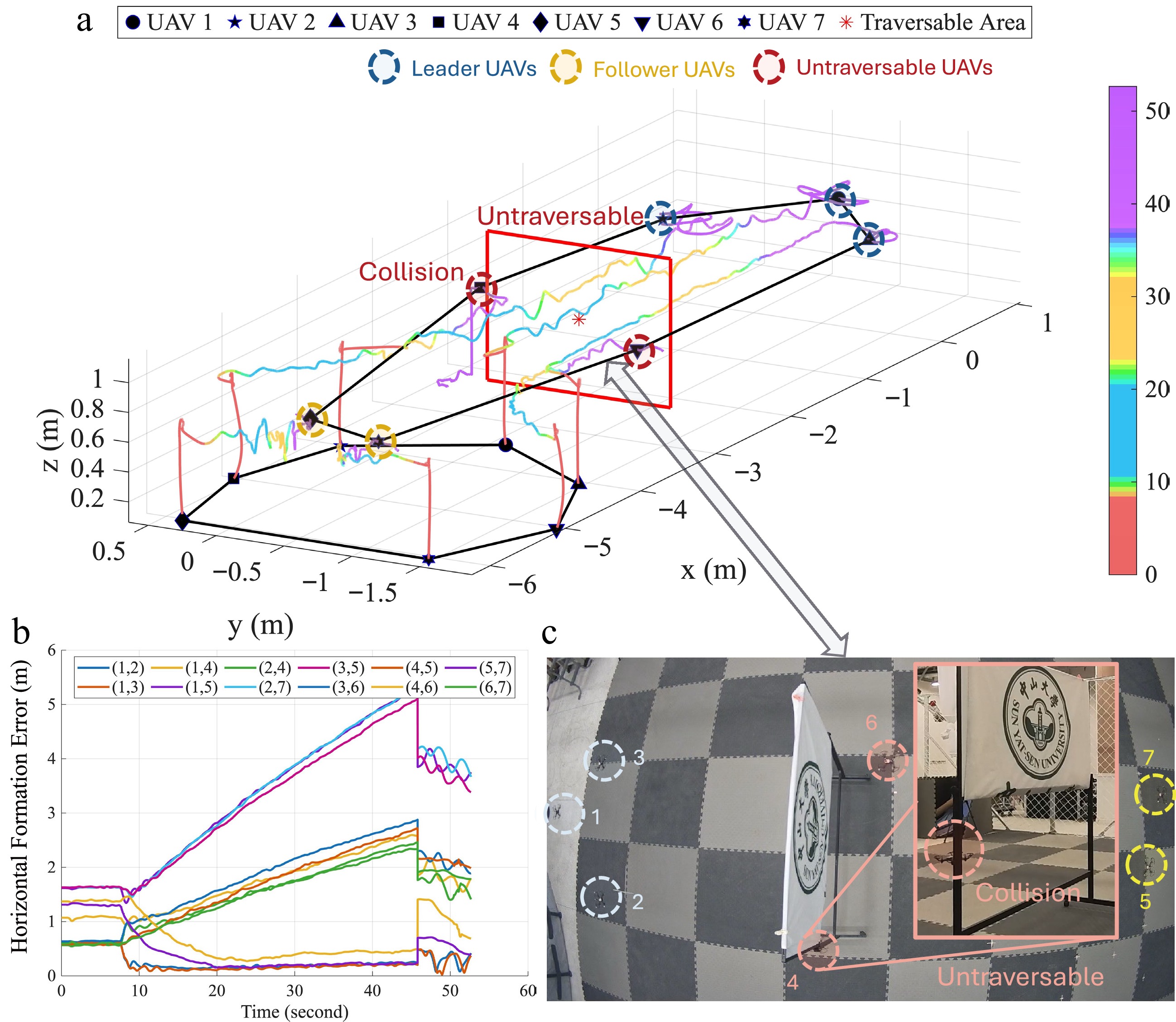
Figure 11.
Experiment 1: Traversing task using the controller without HHVC. (a) The complete trajectory of the travel task and the traversability of the UAV swarm. (b) The formation tracking error of the UAV swarm. (c) The snapshot of a UAV swarm traveling in the constrained area.
-
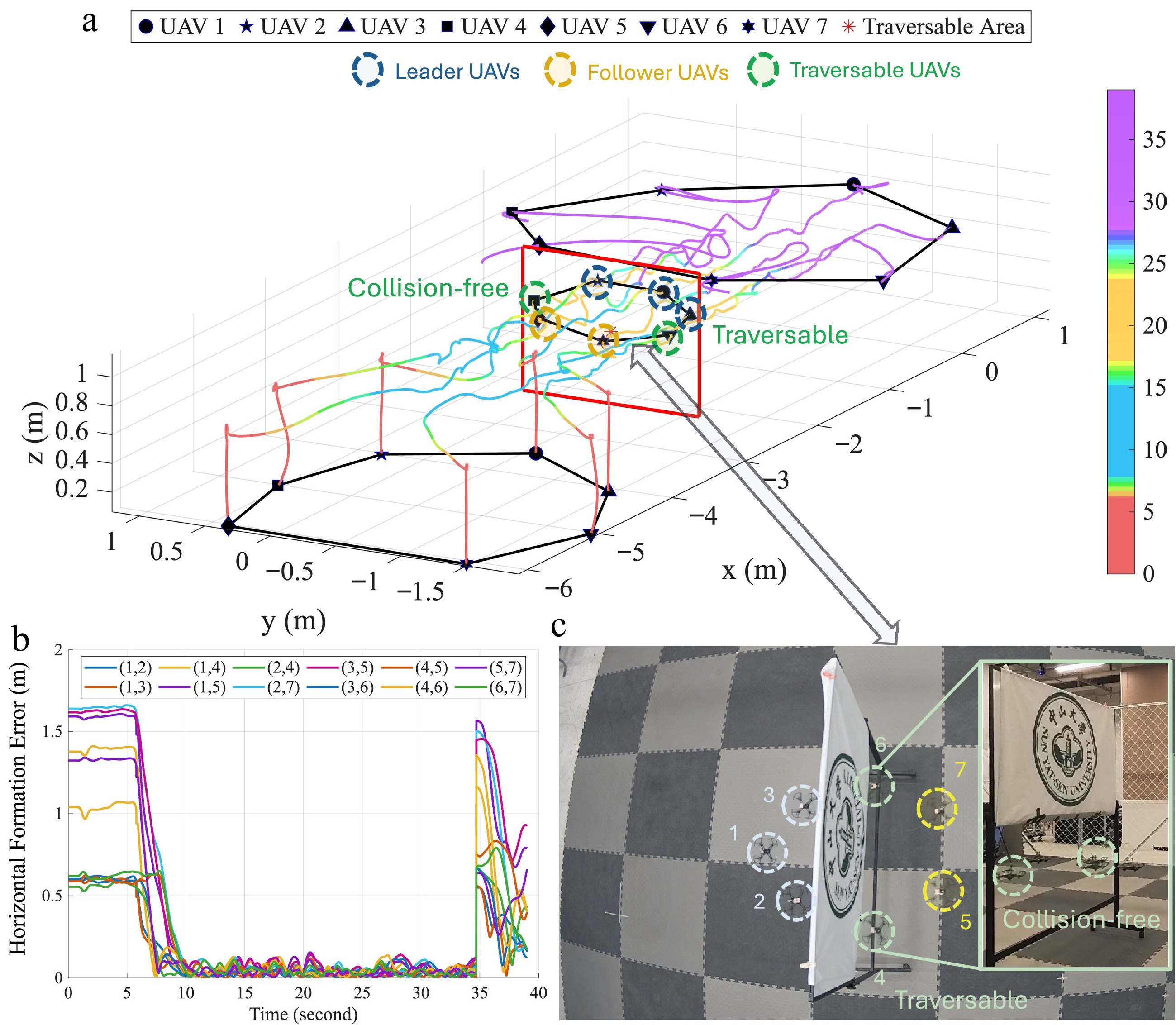
Figure 12.
Experiment 1: Traversing task using the controller with HHVC. (a) The complete trajectory of the travel task and the 3D traversability of the UAV swarm. (b) The formation tracking error of the UAV swarm. (c) The snapshot of the UAV swarm traveling in the constrained area. (
$ k_{\omega}^{xy} = 0.8, k_{\kappa} = 1, k_p^{xy} = 0.83 $ -
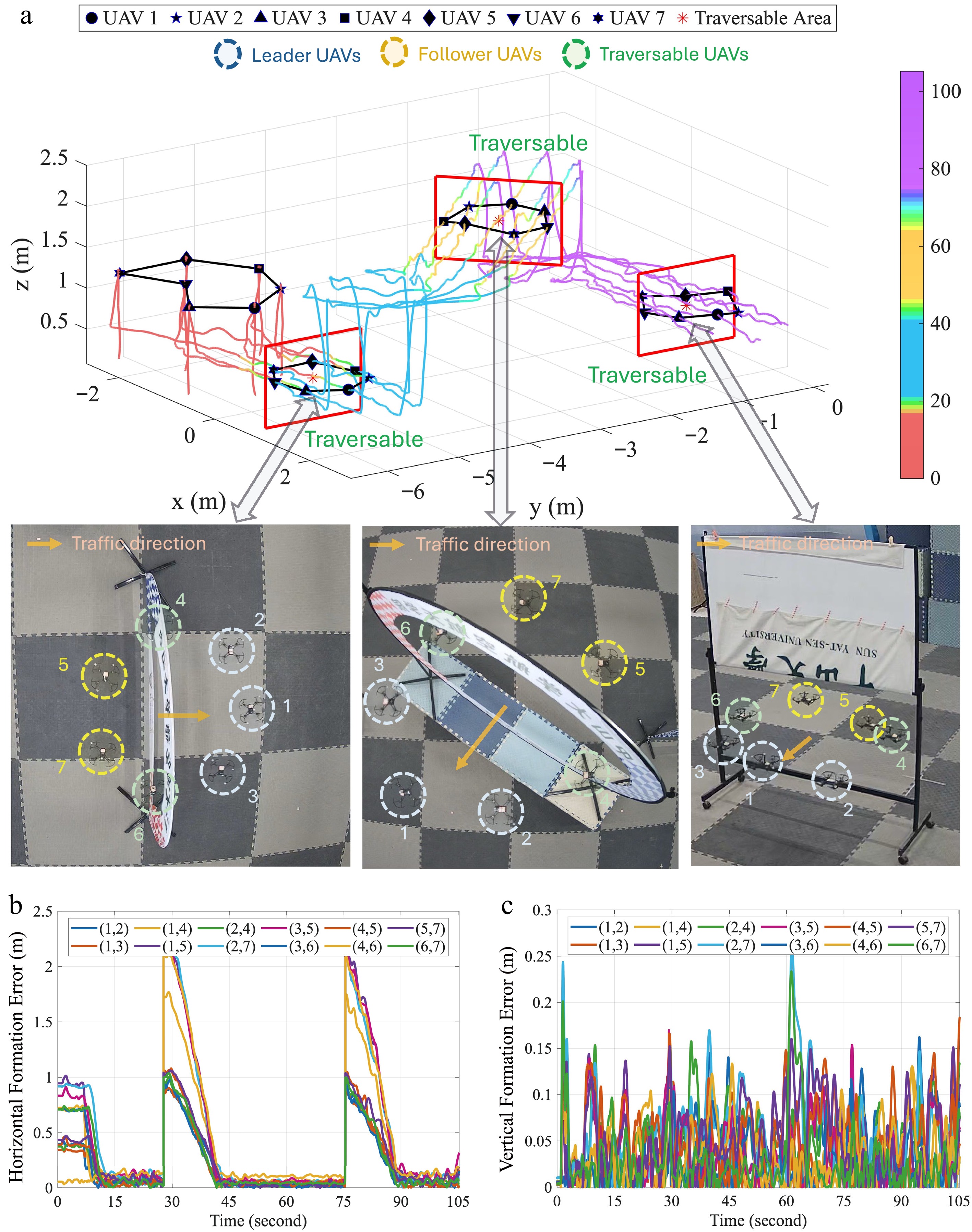
Figure 13.
Experiment 2: Comprehensive formation traversable maneuver under multiple limited traversable areas with controller (11). (a) Complete trajectory and traversable formation in complex limited areas with three snapshots of traveling the different constrained areas. (b) Horizontal formation tracking error. (c) Vertical formation tracking error.
-
Case The purpose of the experiment cases Case 1 To verify the HHVC improves the performance in position control Case 2 To verify the HAC improves the performance in altitude control Case 3 To verify the adaptivity of the controller to diverse maneuvers Table 1.
Simulation cases and purposes.
-
Channel Case 1 Case 2 Case 3 Without HHVC With HHVC Without HVAC With HVAC Position (x) Unsettled 2.58 / / 2.34 Position (y) Unsettled 0.99 / / 0.84 Altitude (z) / / 0.74 0.019 0.02 Table 2.
Lack of cohesiveness
$ {{\Delta }_{f}} $ -
HHVC Cohesiveness $ \Delta_f $ x-axis y-axis Without Unsettled 0.723 With 1.053 0.287 Table 3.
Lack of cohesiveness
$ \Delta_f $
Figures
(13)
Tables
(3)