-
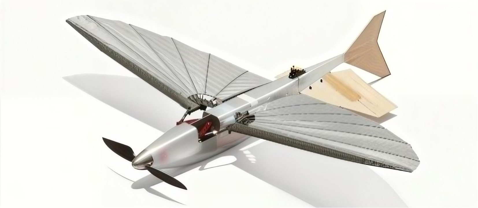
Figure 1.
Digital visualization of the proposed aircraft design.
-
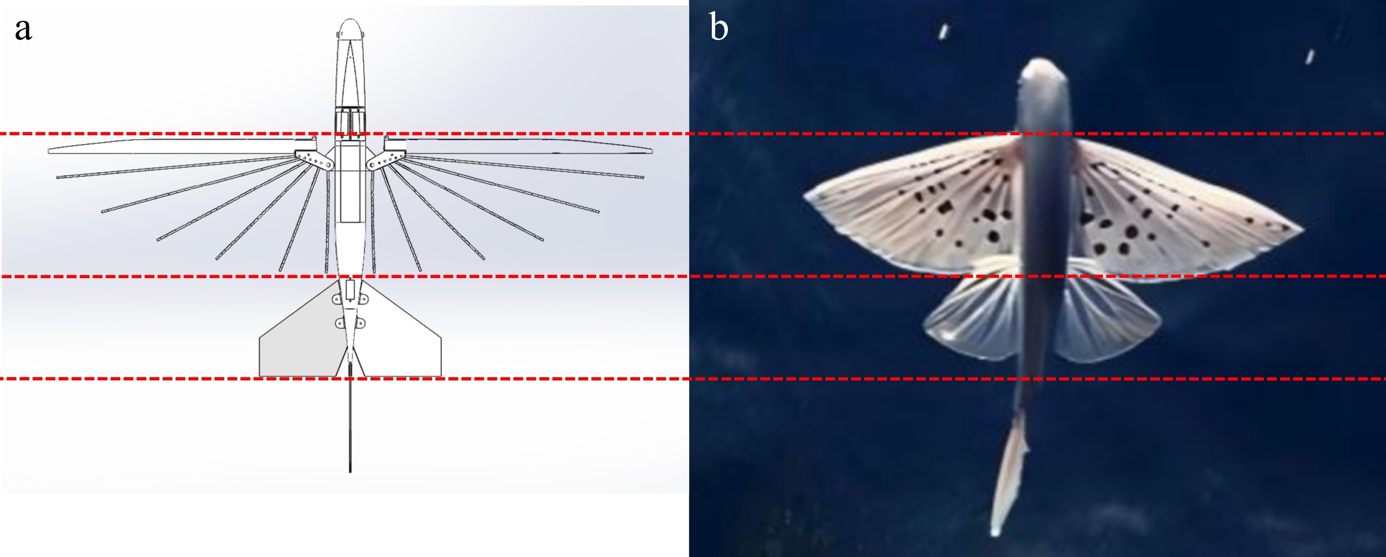
Figure 2.
Layout comparison: (a) the layout design; (b) the real flying fish.
-
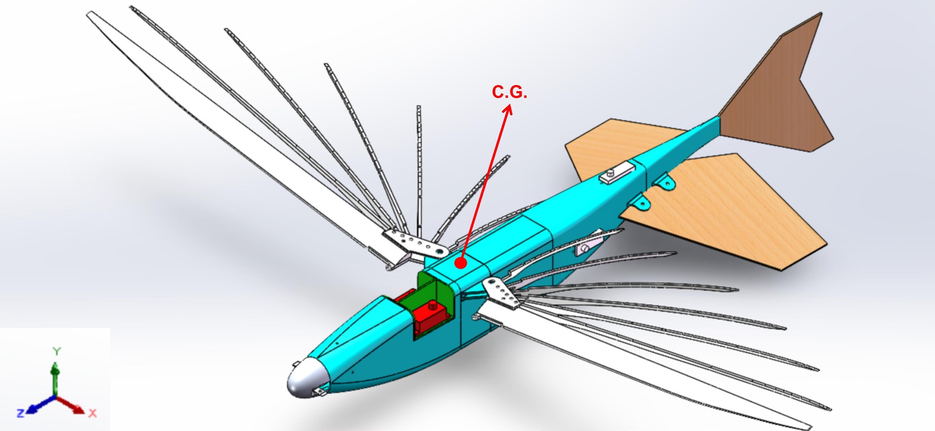
Figure 3.
Weight and CG of the aircraft.
-
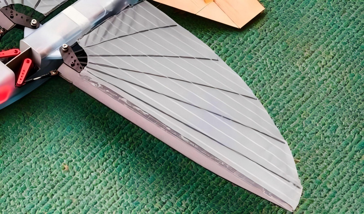
Figure 4.
Wing configuration.
-
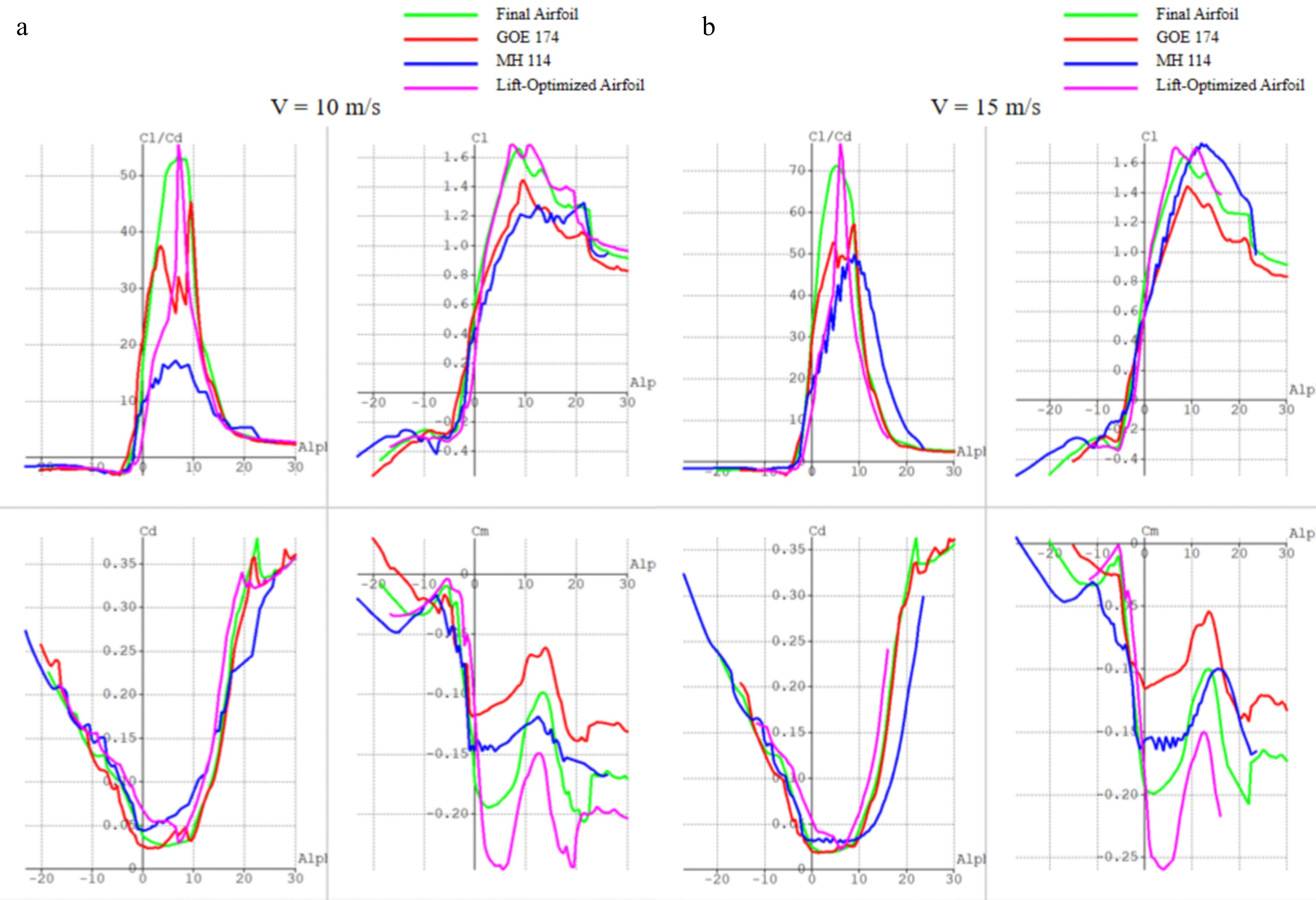
Figure 5.
Comparison of relevant airfoils: (a) V = 10 m/s; (b) V = 15 m/s.
-
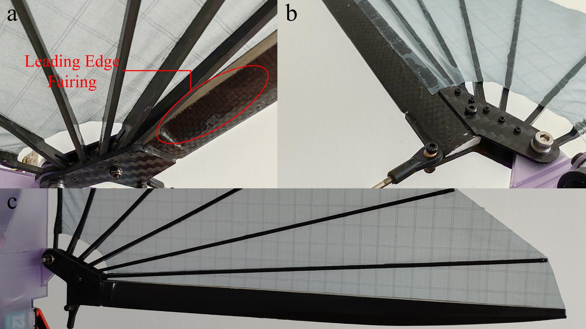
Figure 6.
The leading edge: (a) lower surface; (b) upper surface; (c) overall view.
-
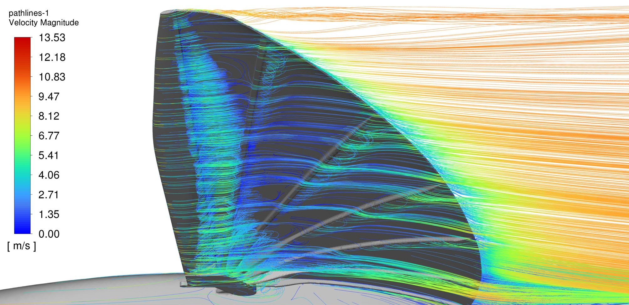
Figure 7.
Flow field visualization of the lower leading edge.
-
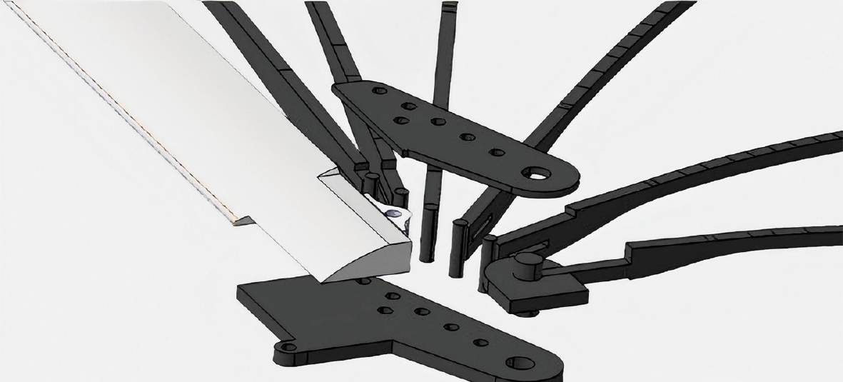
Figure 8.
Supporting rib skeleton and collinear distributed shaft structure.
-
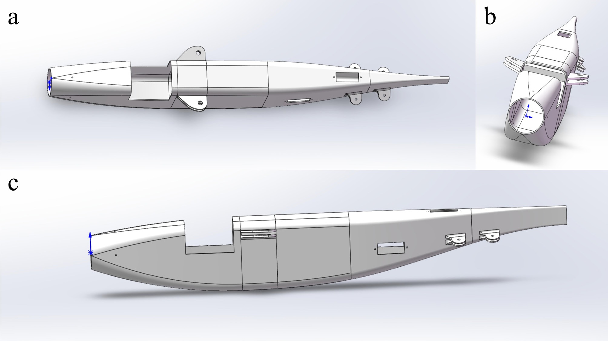
Figure 9.
3D model of the fuselage: (a) top view; (b) front view; (c) side view.
-
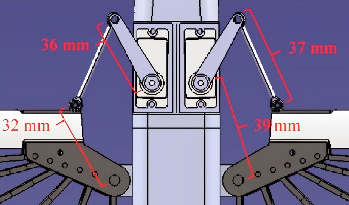
Figure 10.
Four-bar folding mechanism.
-
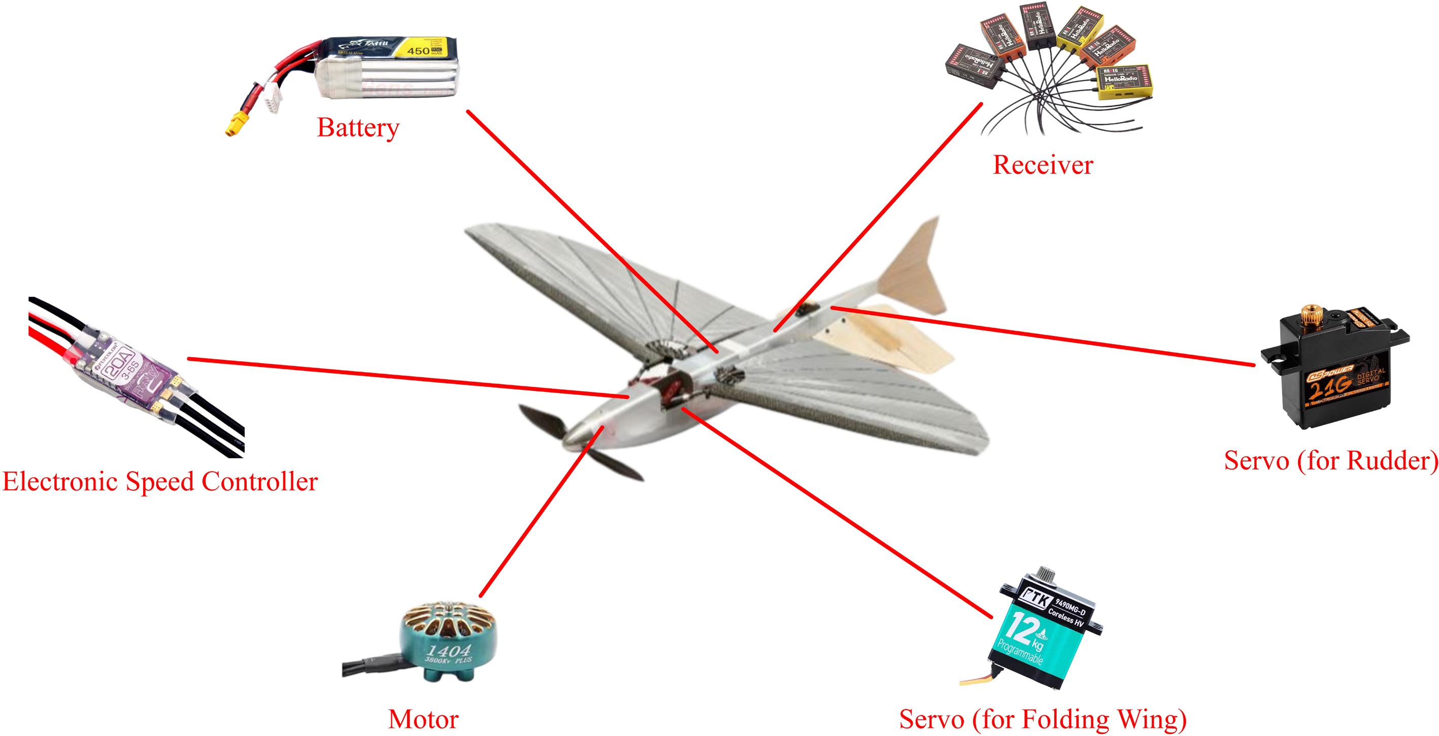
Figure 11.
Power system and electronic components of the aircraft prototype.
-
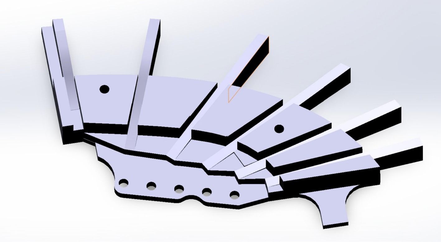
Figure 12.
Wing assembly jig design.
-
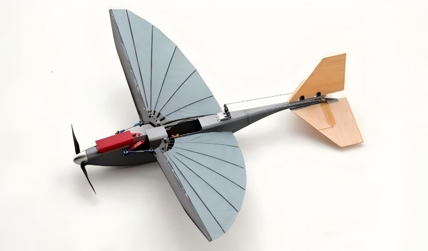
Figure 13.
The conventional configuration validation aircraft.
-
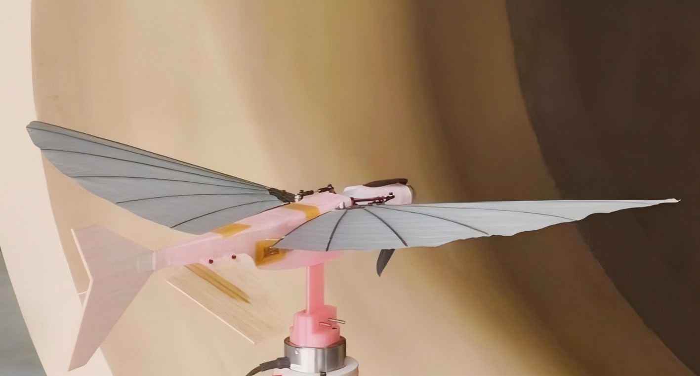
Figure 14.
Test model in the wind tunnel.
-
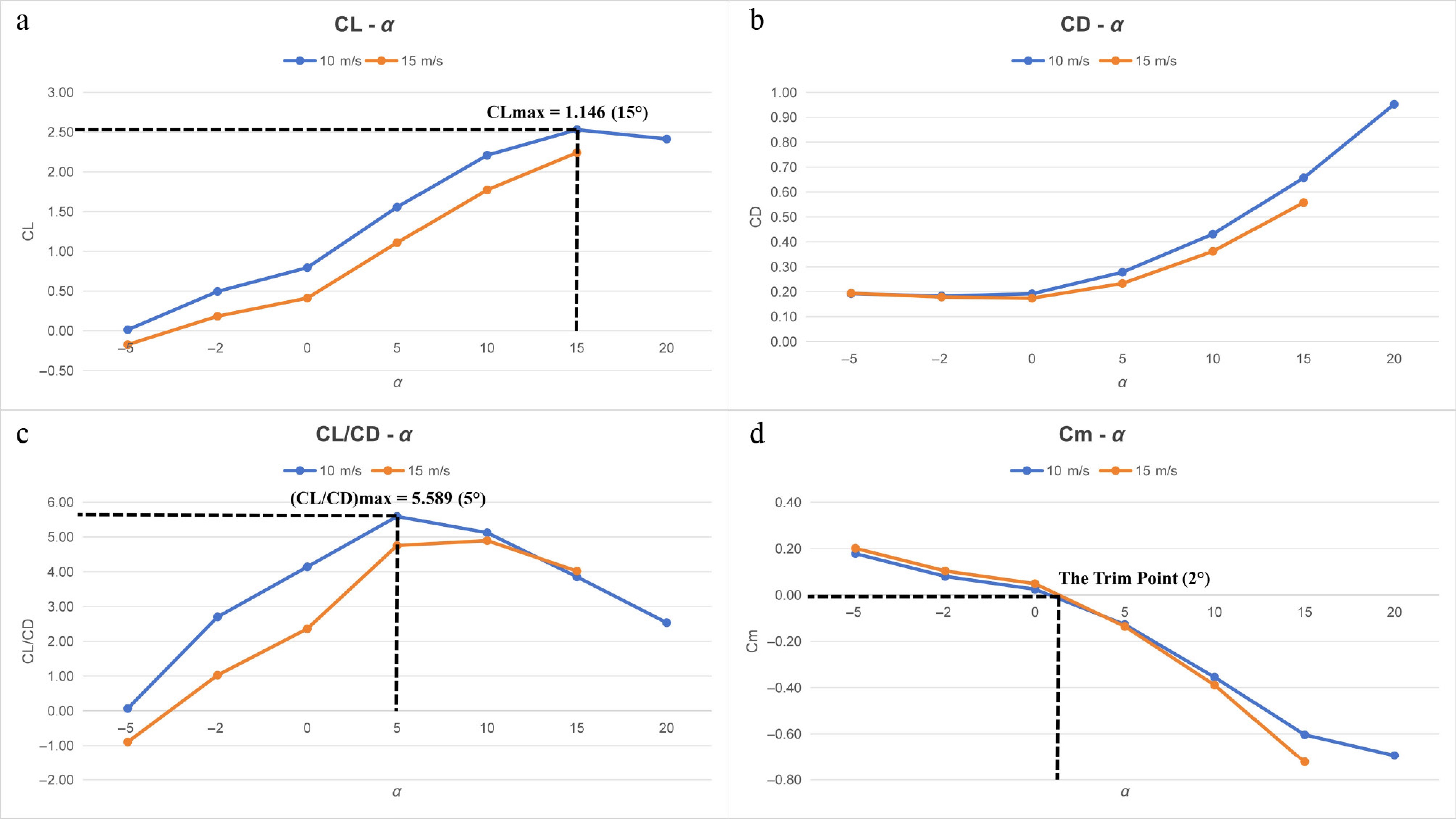
Figure 15.
Wind tunnel test results: (a) CL; (b) CD; (c) CL/CD; (d) Cm.
-
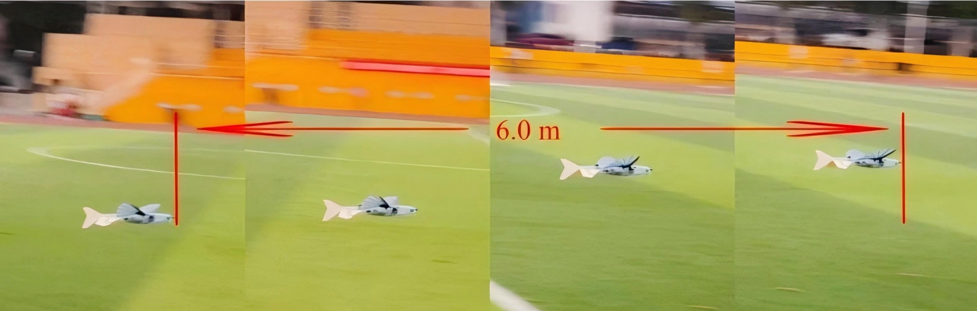
Figure 16.
Flight test (0.2 s continuous flight slices).
-
Component or equipment Weight Fuselage 52.14 g Wings 43.82 g Horizontal tail 5.54 g Vertical tail 2.77 g Propeller cowling 8.73 g Motor 10 g Electronic speed controller 15 g Battery 33 g Receiver 3 g Servos 34 g Table 1.
Component weights of the aircraft.
-
Parameter Value Length 450 mm Wingspan 623 mm Fuselage length 350 mm Internal volume 350 mL Frontal area 1,650 mm2 (55 mm × 30 mm) CLmax 1.146 (L/D)max 5.589 Maximum gross weight 270 g Vmax 30 m/s Table 2.
Key parameters of the aircraft.
Figures
(16)
Tables
(2)