-
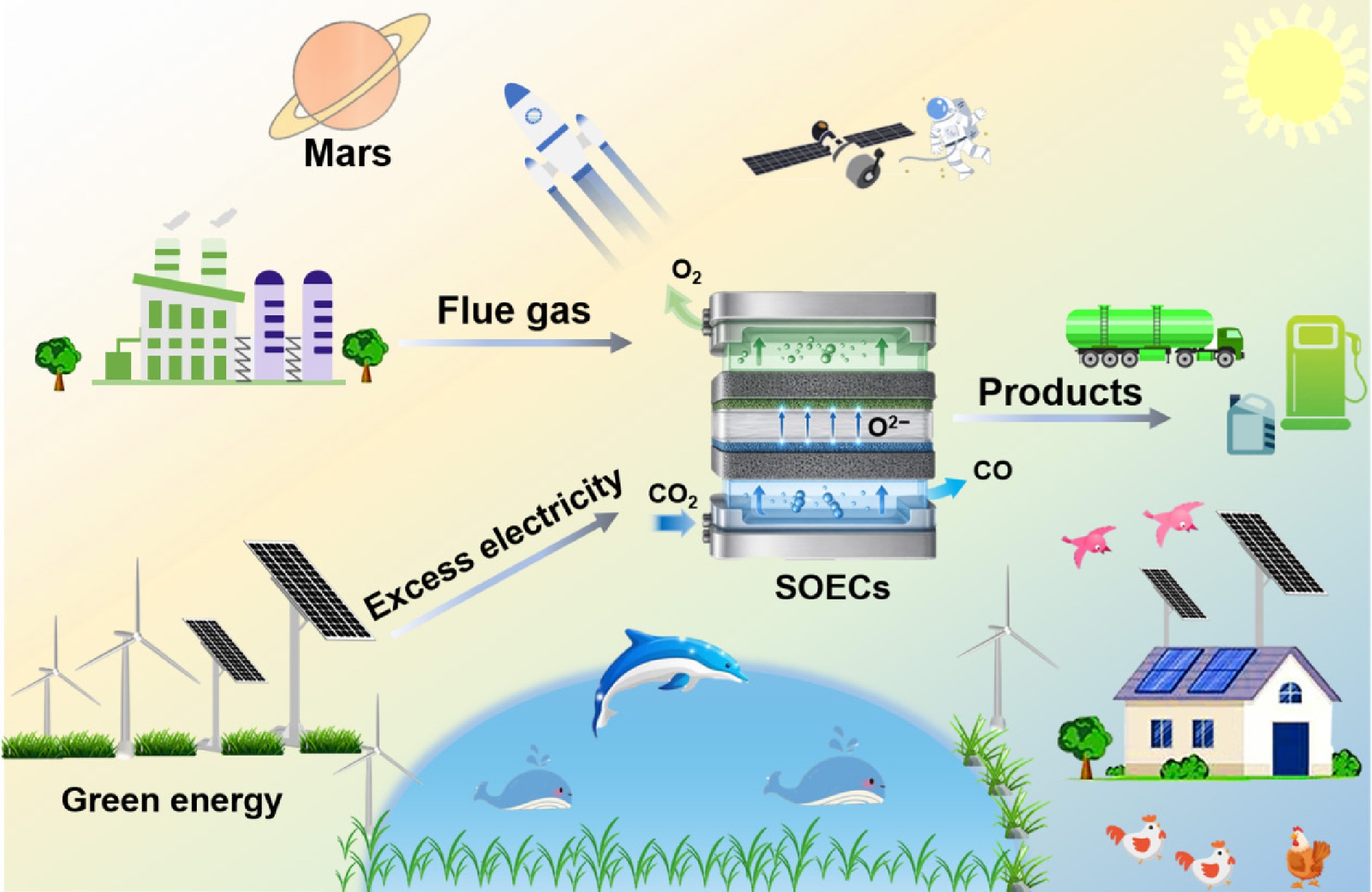
Figure 1.
Conceptual overview of SOECs' functionality in future renewable-rich energy systems, illustrating the interconnections among power, gas, thermal, and transport networks, along with deep space exploration applications.
-
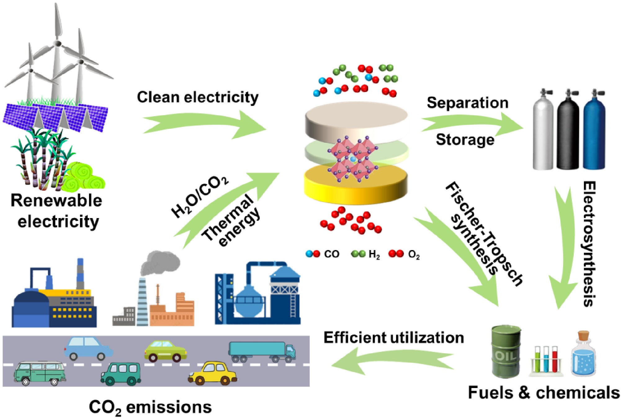
Figure 2.
Illustration of the conceived carbon cycle by SOECs.
-
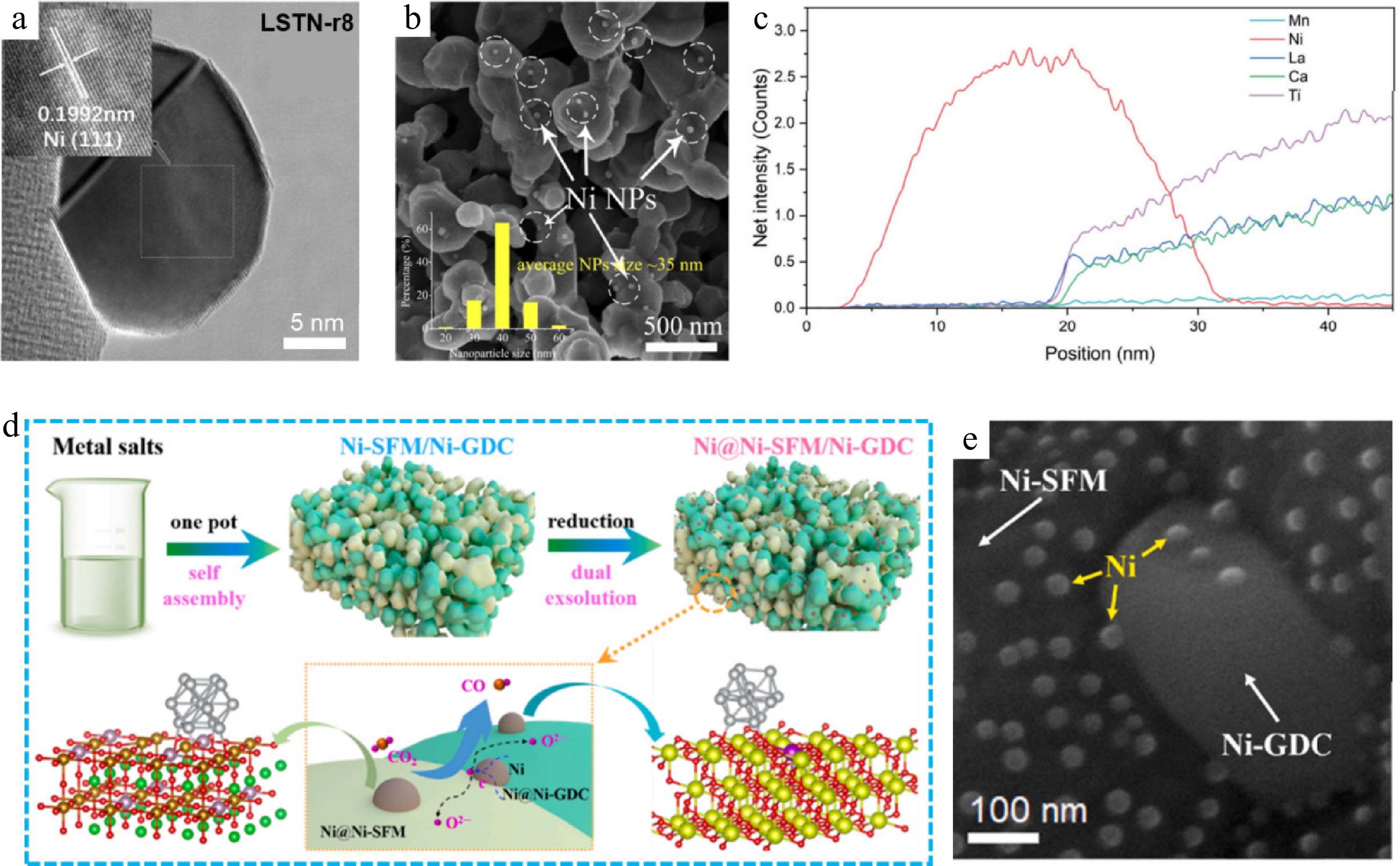
Figure 3.
(a) High-resolution TEM images of LSTN-r8[71]. Reproduced with permission. Copyright 2023, Elsevier. (b) The SEM images of LCTNi-Ce electrodes reduced at 800 C for 3 h in pure H2[72]. Reproduced with permission. Copyright 2022, RSC. (c) EDX line scan of the exsolved Ni NPs and the perovskite outer layers[73]. Reproduced with permission. Copyright 2024, Wiley. (d) The Synthesis scheme, and (e) SEM images of Ni@Ni-SFM/Ni-GDC[75]. Reproduced with permission. Copyright 2023, Elsevier.
-
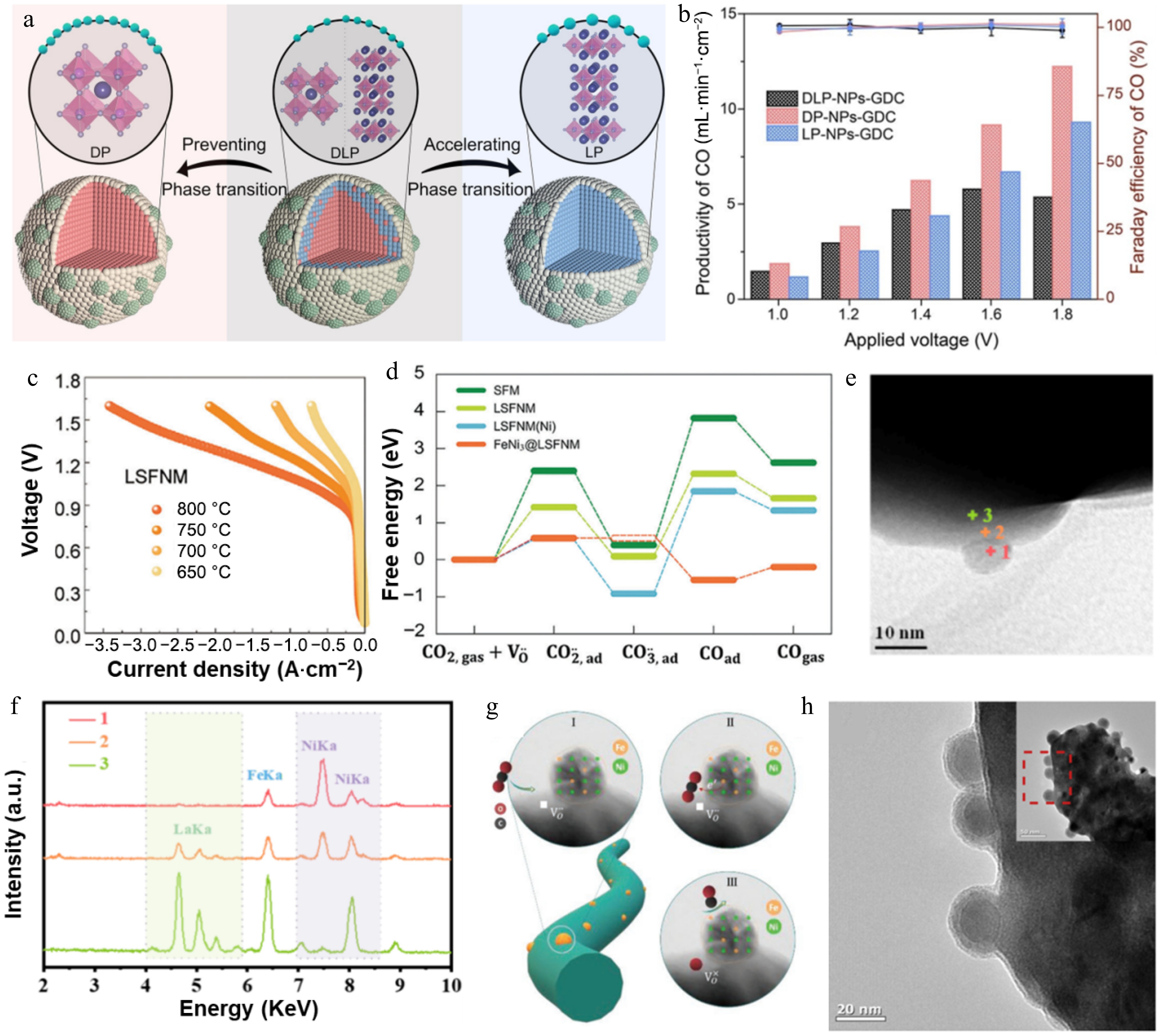
Figure 4.
(a) Design scheme of the Sr2Fe1.2Ni0.3Mo0.5O6-δ-based exsolution-facilitated perovskites with exsolved NPs, with a pure double perovskite, layered perovskite, and their composite perovskite as scaffolds, respectively[78]. Reproduced with permission. Copyright 2023, Wiley. (b) The corresponding CO productivity (histogram) and Faraday efficiency of CO for DP-NPs-GDC and comparison samples[78]. Reproduced with permission. Copyright 2023, Wiley. (c) Pure CO2 electrolysis performance for the cells and (d) the calculated free energy diagram for CO2RR on impregnated LSFNM cathodes[79]. Reproduced with permission. Copyright 2024, Wiley. (e) Bright-field STEM image and (f) EDS results at the FeNi@LSFN interface[80]. Reproduced with permission. Copyright 2026, ACS Publications. (g) CO2 conversion processes over perovskite fibers decorated with exsolved active NPs[81]. Reproduced with permission. Copyright 2023, Wiley. (h) Magnified TEM image of reduced PSMFN[82]. Reproduced with permission. Copyright 2024, RSC.
-
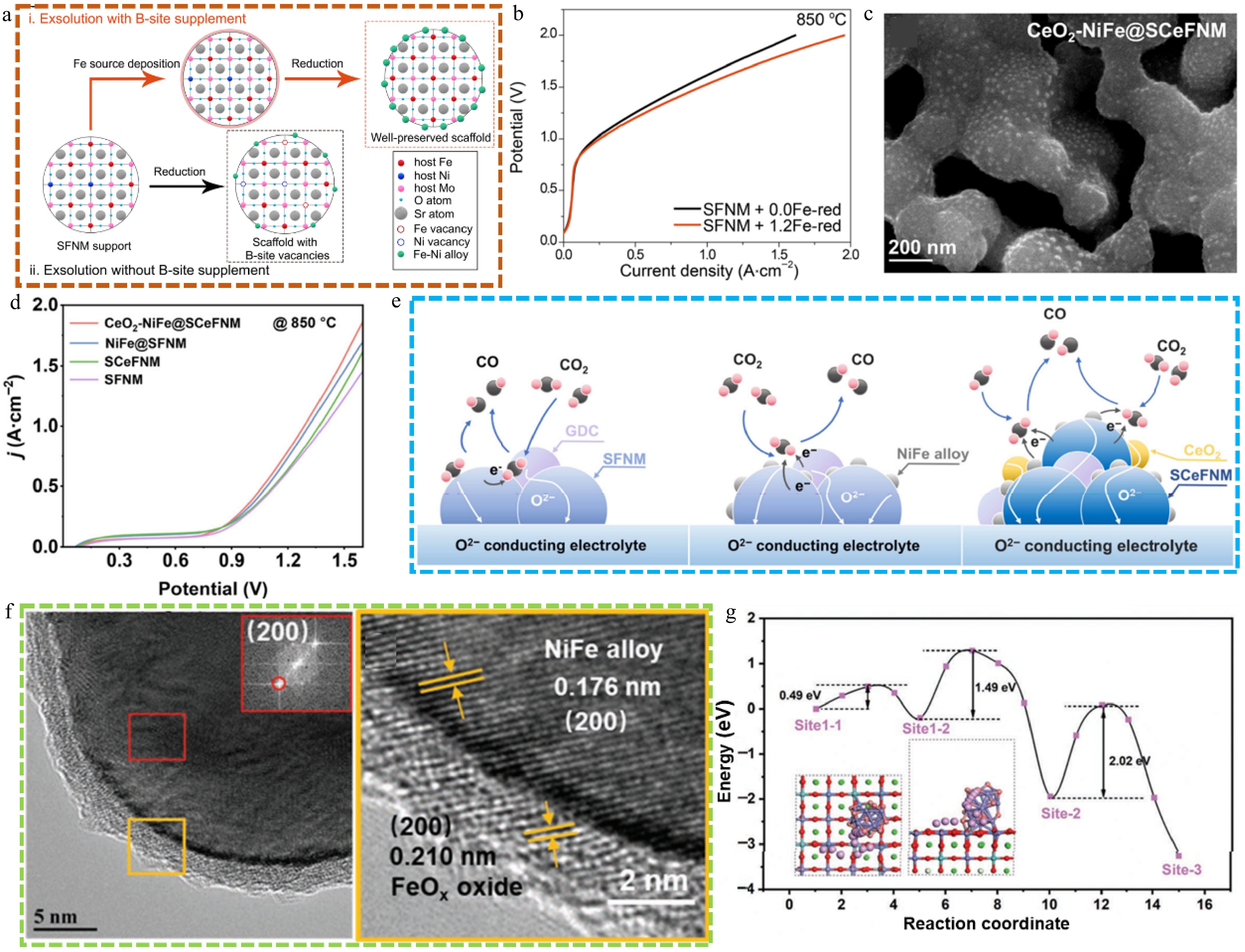
Figure 5.
(a) Schematic illustration of exsolution with and without B-site supplement, and (b) current density-voltage curves on SFNM[84]. Reproduced with permission. Copyright 2022, Springer Nature. (c) SEM image of CeO2- NiFe@SCeFNM. (d) I-V curves and (e) schematic illustrations of possible reaction pathways for CO2 electrolysis over SFNM, NiFe@SFNM, and CeO2-NiFe@SCeFNM[85]. Reproduced with permission. Copyright 2025, RSC. (f) TEM and HRTEM images of PSNFM-NFA@FeO and (g) diffusion energy barriers of O atoms on the PSNFM-NFA@FeO surface[86]. Reproduced with permission. Copyright 2022, Wiley.
-
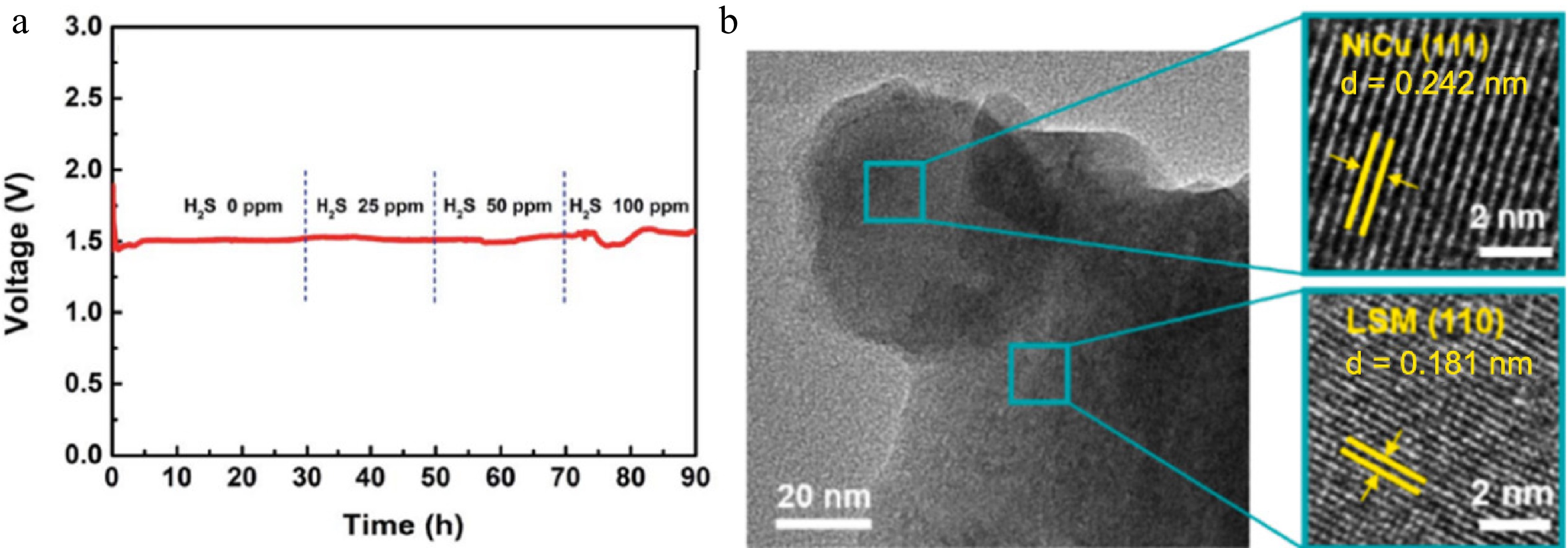
Figure 6.
(a) Voltage profile of the single cell with the CoNi-R.P.LSCM cathode at a constant current density of 700 mA·cm−2 at 850 °C and using the reaction gas (30% CO/CO2) streams that contain different H2S contents[87]. Reproduced with permission. Copyright 2020, RSC. (b) HR-TEM of reduced LSM-Ni0.050Cu0.050[88]. Reproduced with permission. Copyright 2024, Elsevier.
-
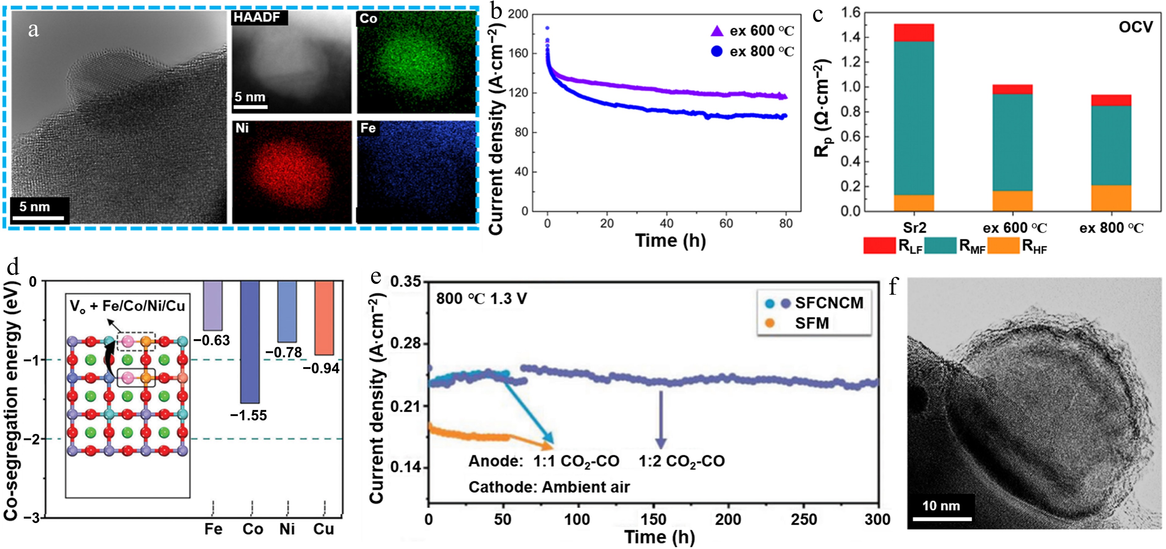
Figure 7.
(a) HR-TEM image and the EDS mapping images of an FeCoNi ternary alloy nanoparticle exsolved from SrxFeCo0.2Ni0.2Mn0.1Mo0.5O6-δ at 600 °C, 4 h, and a 5% H2/Ar atmosphere[92]. Reproduced with permission. Copyright 2024, ACS Publications. (b) CO2 electrolysis measurements at 800 °C for 80 h at 1.2 V for cells after in-situ exsolution at 600 and 800 °C[92]. Reproduced with permission. Copyright 2024, ACS Publications. (c) Total Rp and its three contributions (RLF, RMF, and RHF; LF, MF, and HF being low, medium, and high frequency, respectively) at OCV[92]. Reproduced with permission. Copyright 2024, ACS Publications. (d) Schematic illustration of the computational model for co-segregation energy and the comparison of the co-segregation energy[93]. Reproduced with permission. Copyright 2024, Wiley. (e) Long-term electrochemical stability of QA@SFO during CO2 electrolysis at 1.3 V[93]. Reproduced with permission. Copyright 2024, Wiley. (f) HR-TEM images of reduced HE-PBM with exsolved nanoparticles[94]. Reproduced with permission. Copyright 2023, Elsevier.
-
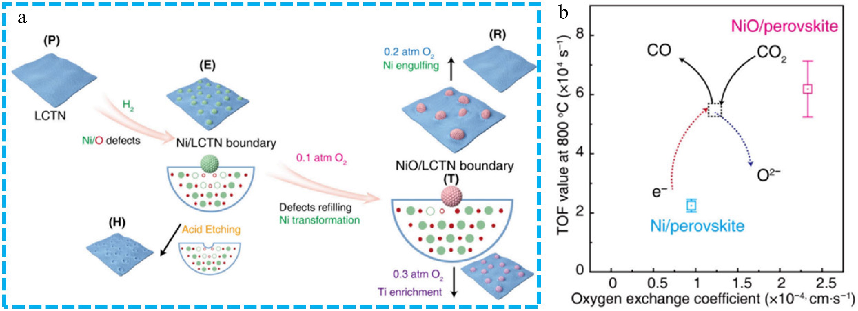
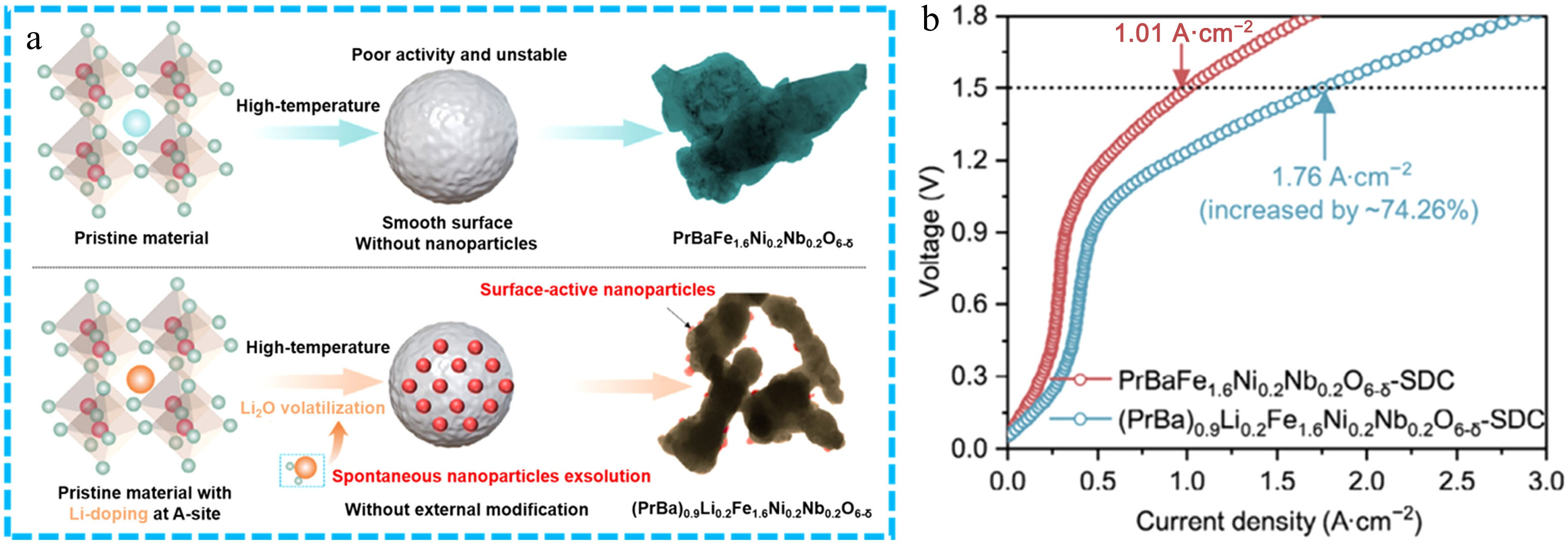
Figure 8.
(a) Schematic of the construction of perovskite platforms. (b) The TOF vs kchem plot of individual exsolved Ni and NiO sites. AIMD simulations of the diffusion of oxygen ions across LCTN and NiO/LCTN surfaces at 300 K, including the energy landscape and atomic-scale diffusion pathway[95]. Reproduced with permission. Copyright 2025, ACS Publications.
-
-
Fuel electrode Electrolyte Air electrode Exsolved nanoparticles Operating conditions Current density @ Potential
(A·cm−2@V)Stability Faradaic efficiency CO production
(mL·min−1·cm−2)Ref. LSTN-r8 8YSZ (~500 μm) LSCF Ni (5% H2/N2, 800 °C for 10 h) 85% CO2 -18% CO
(30 mL·min−1)1.50@2.0 (800 °C) 35 h (2.0 V, 800 °C) 80.2% 8.379 [71] LCTNi-Ce LSGM (~300 μm) LSCF-GDC Ni (H2, 800 °C for 3 h) 50% CO2−50% H2
(50 mL·min−1)0.557@1.3 (800 °C) 2 h (0.24 A·cm−2, 800 °C) ~100% ~1.7 [72] LCNMT5 ScCeSZ (150 μm) LSM Ni (5% H2/N2, 900 °C) 77.6% CO2−19.4 H2−3% H2O (50 mL·min−1) 2.89@1.8 (900 °C) 133 h (1.2 V, 900 °C) − − [73] CZO-Ni0.1 YSZ CZO-Ni0.1 Ni (5% H2/Ar, 750 °C for 20 h) CO2 0.78@1.6 (850 °C) 100 h (1.6 V, 850 °C) 99% 5.42 [74] Ni-SFM/Ni-GDC LSGM (270 μm) PBSCF/GDC Ni (H2, 800 °C for 0.5 h) Pure CO2 (50 mL·min−1) 1.72@1.5 (800 °C) 100 h (1.2 V, 800 °C) 95.2% − [75] DP-NPs-GDC YSZ (250~300 μm) LSCF-GDC NiFe alloy
(5% H2/N2, 850 °C for 2 h)Pure CO2 (50 mL·min−1) 0.95@1.4 (850 °C) 100 h (1.4 V, 850 °C) ~100% 9.17 [78] LSFNM LSGM (~200 μm) SBSCO FeNi3
(97% H2−3% H2O, 800 °C)Pure CO2 (100 mL·min−1) 3.07@1.5 (800 °C) 100 h (1.5 V, 750 °C) − − [79] LSFN LSGM (~550 μm) LSCF-GDC FeNi alloy Pure CO2 (15 mL·min−1) 0.88@1.6 (800 °C) 100 h (1.2 V, 800 °C) 100% 6.0 [80] LCNFT YSZ (200 μm) (La0.8Sr0.2)0.95MnO3 FeNi alloy
(5% H2/Ar, 800 °C for 10 h)Pure CO2 (20 mL·min−1) 0.75@1.6 (900 °C) − − − [81] PSMFN LSGM (230 μm) PSMFN-GDC FeNi alloy
(100% H2, 800 °C for 0.5 h)30%CO/CO2 (50 mL·min−1) 1.02@1.5 (800 °C) ~90 h (0.39 A·cm−2, 750 °C) ~91% ~3.54 [82] PBFN YSZ (300 μm) PBFN FeNi alloy
(5% H2/N2, 800 °C for 5 h)Pure CO2 (50 mL·min−1) 0.843@2 (800 °C) ~60 h (0.28 A·cm−2, 800 °C) − − [83] SFNM + 1.2 Fe-red YSZ LSCF-GDC FeNi alloy
(5% H2/N2, 800 °C for 2 h)Pure CO2 (100 mL·min−1) 1.13@1.6 (850 °C) 100 h (1.6 V, 850 °C) ~90% ~9.2 [84] CeO2−NiFe@SCeFNM LSGM LSCF-GDC NiFe
(5%H2/Ar, 800 °C for 2 h)Pure CO2 (50 mL·min−1) 1.57@1.5 (850 °C) 120 h (1.2 V, 850 °C) > 96% 10.32 [85] PSNFM-NFA@FeO LSGM (200 μm) LSCF-GDC FeNi alloy
(97% H2−3% H2O, 800 °C)Pure CO2 (50 mL·min−1) 1.58@1.4 (800 °C) 500 h (0.5 A·cm−2, 800 °C) 95% 9.54 [86] LSCNM LSGM (300 μm) LSCF-GDC NiCo alloy
(20% H2/N2, 800 °C)30%CO/CO2 0.703@1.3 (850 °C) 90 h (30% CO/CO2 with H2S, 850 °C) 97.8% ~4.7 [87] LSM-Ni0.05Cu0.05 YSZ (272 μm) LSM-Ni0.05Cu0.05−SDC CuNi alloy
(5% H2/Ar, 800 °C)CO2 0.75@1.3 (850 °C) 100 h (1.6 V, 800 °C) > 95.5% 9.51 [88] Sr2FeCo0.2
Ni0.2Mn0.1Mo0.5O6−δScSZ (150 μm) CGO-LSGF FeCoNi alloy
(5% H2/Ar, 600 °C for 4 h)15% CO2/Ar (100 mL·min−1) 0.4@1.3 (800 °C) 80 h (1.2 V, 800 °C) > 90% ~4.7 [92] SFCNCM LSGM LSCF-GDC FeCoNiCu alloy
(3H2O%-H2, 600 °C)CO2 : CO = 1:2
(40 mL·min−1)0.45@1.5 (800 °C) 300 h (1.3 V, 800 °C) − − [93] HE-PBM LSGM (250 μm) HE-PBM-SDC FeCoNiCu alloy
(67% CO2−33% CO,
60 mL·min−1)67% CO2−33% CO
(60 mL·min−1)1.21@2.0 (800 °C) 80 h (1.2 V, 800 °C) > 95% ~4.4 [94] PBLFNN LSGM (~200 μm) LSCF-SDC FexNi1-xO (Li2O volatilization) Pure CO2 (50 mL·min−1) 1.76@1.5 (800 °C) 200 h (0.75 A·cm−2, 800 °C) 98.98% 10.73 [96] Table 1.
Exsolved Ni-based cathode materials reported for SOECs applications.
-
Cathode Exsolved nanoparticles Material systems Induction method Advantages Limitations Ref. LSTN-r8 Ni Perovskite oxide 5% H2/N2, 800 °C for 10 h The density, size, and distribution of the exsolved Ni NPs are controllable Faraday's efficiency and current density of CO2 RR is low, and its stability is poor; susceptible to carbon coking [71] LCTNi-Ce H2, 800 °C for 3 h [72] LCNMT5 5% H2/N2, 900 °C [73] CZO-Ni0.1 Ni Fluorite-type oxide 5% H2/Ar, 750 °C for 20 h Relatively high stability Relatively low activity; susceptible to carbon coking [74] Ni-SFM/Ni-GDC Ni Dual-exsolved heterointerface
of perovskite and fluorite-type oxideH2, 800 °C for 0.5 h Relatively high current density of CO2RR and stability Sr segregation during long-term operation; susceptible to carbon coking [75] DP-NPs-GDC NiFe alloy Double perovskite oxide 5% H2/N2, 850 °C for 2 h Relatively high stability and activity Sr segregation during long-term operation; volume expansion of electrode materials [78] LSFNM 97% H2−3% H2O, 800 °C [79] LSFN − [80] LCNFT NiFe alloy Perovskite oxide fibers 5% H2/Ar, 800 °C for 10 h High specific surface area and abundant active sites Poor contact at the electrode/electrolyte interface; poor stability [81] PSMFN NiFe alloy Ruddlesden–Popper structure 100 %H2, 800 °C for 0.5 h High ionic electron conductivity, relatively high activity Poor stability under harsh conditions; element segregation at the A site [82] PBFN NiFe alloy Perovskite oxide 5% H2/N2, 800 °C for 5 h High electrochemical performance. Low production cost Poor stability under harsh conditions; element segregation at the A site [83] SFNM+1.2Fe-red NiFe alloy 5% H2/N2, 800 °C for 2 h High electrochemical performance Poor stability [84] CeO2−NiFe@SCeFNM NiFe alloy + CeO2 5% H2/Ar, 800 °C for 2 h High ionic electron conductivity, relatively high activity Poor stability under harsh conditions; volume expansion of electrode materials [85] PSNFM-NFA@FeO NiFe alloy + FeOx Double perovskite oxide 97% H2−3% H2O, 800 °C Enhanced CO2 adsorption, relatively high activity Poor stability [86] LSCNM NiCo alloy Ruddlesden–Popper structure 20% H2/N2, 800 °C Sulfur-tolerant Relatively low activity, poor stability [87] LSM-Ni0.05Cu0.05 NiCu alloy Perovskite oxide 5% H2/Ar, 800 °C Stability of the active site Relatively low activity, poor stability [88] Sr2FeCo0.2;
Ni0.2Mn0.1Mo0.5O6−δNiFeCo alloy Double perovskite oxide 5% H2/Ar, 600 °C for 4 h High ionic electron conductivity Relatively low activity, poor stability [92] SFCNCM FeCoNiCu alloy Layered perovskite oxide 3H2O%-H2, 600 °C High ionic electron conductivity Relatively low activity, poor stability [93] HE-PBM FeCoNiCu alloy Perovskite oxide 67% CO2−33% CO Low production cost Relatively low activity [94] PBLFNN FexNi1-xO Perovskite oxide Li2O volatilization Enhanced CO2 adsorption Poor stability [96] Table 2.
The systematically compared various exsolved Ni-based nanoparticles mentioned in section Research progress of SOECs for CO2 electrolysis.
Figures
(9)
Tables
(2)