-
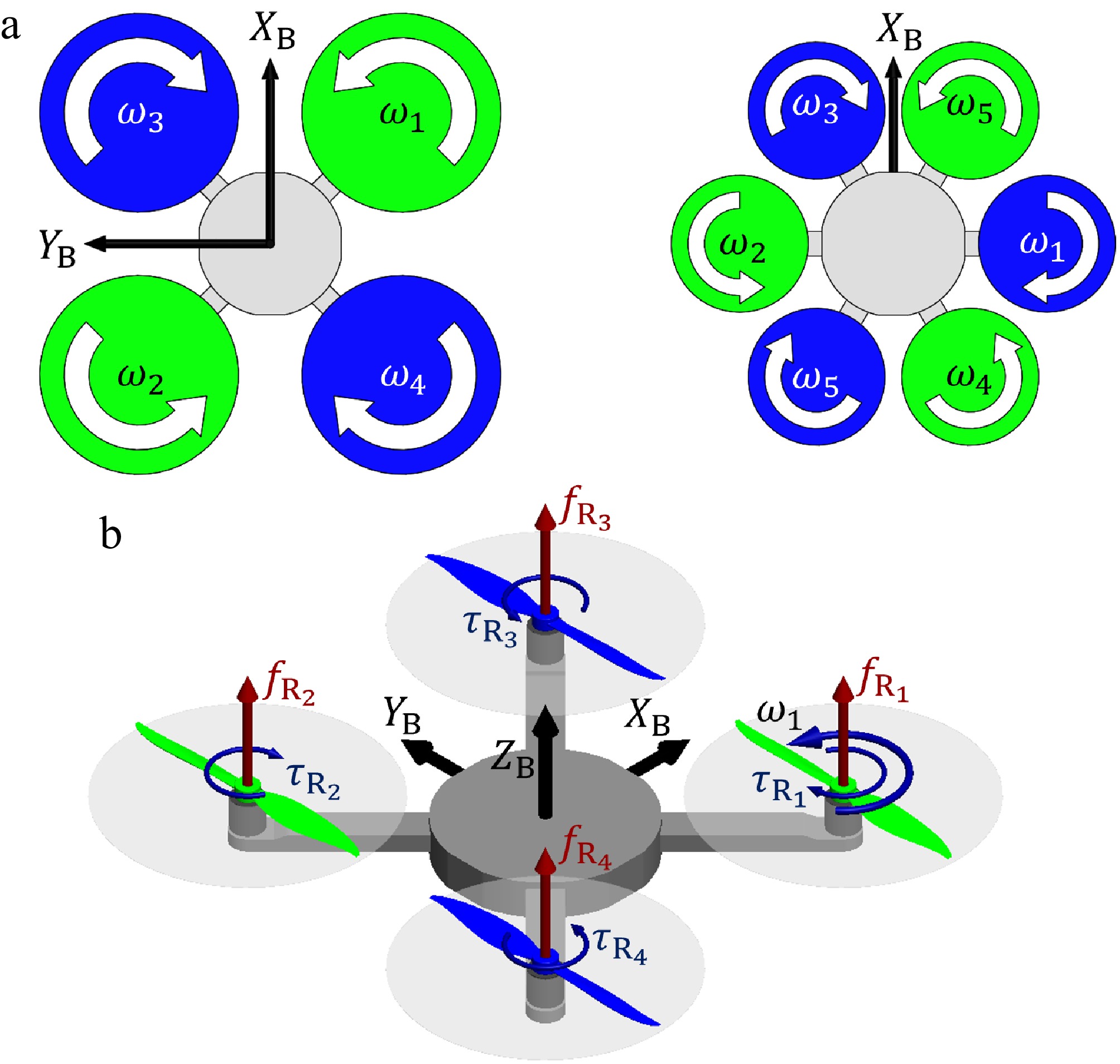
Figure 1.
Conventional multirotor configurations: (a) symmetric rotor layout with an even number of rotors; (b) conventional quadrotor X-configuration.
-
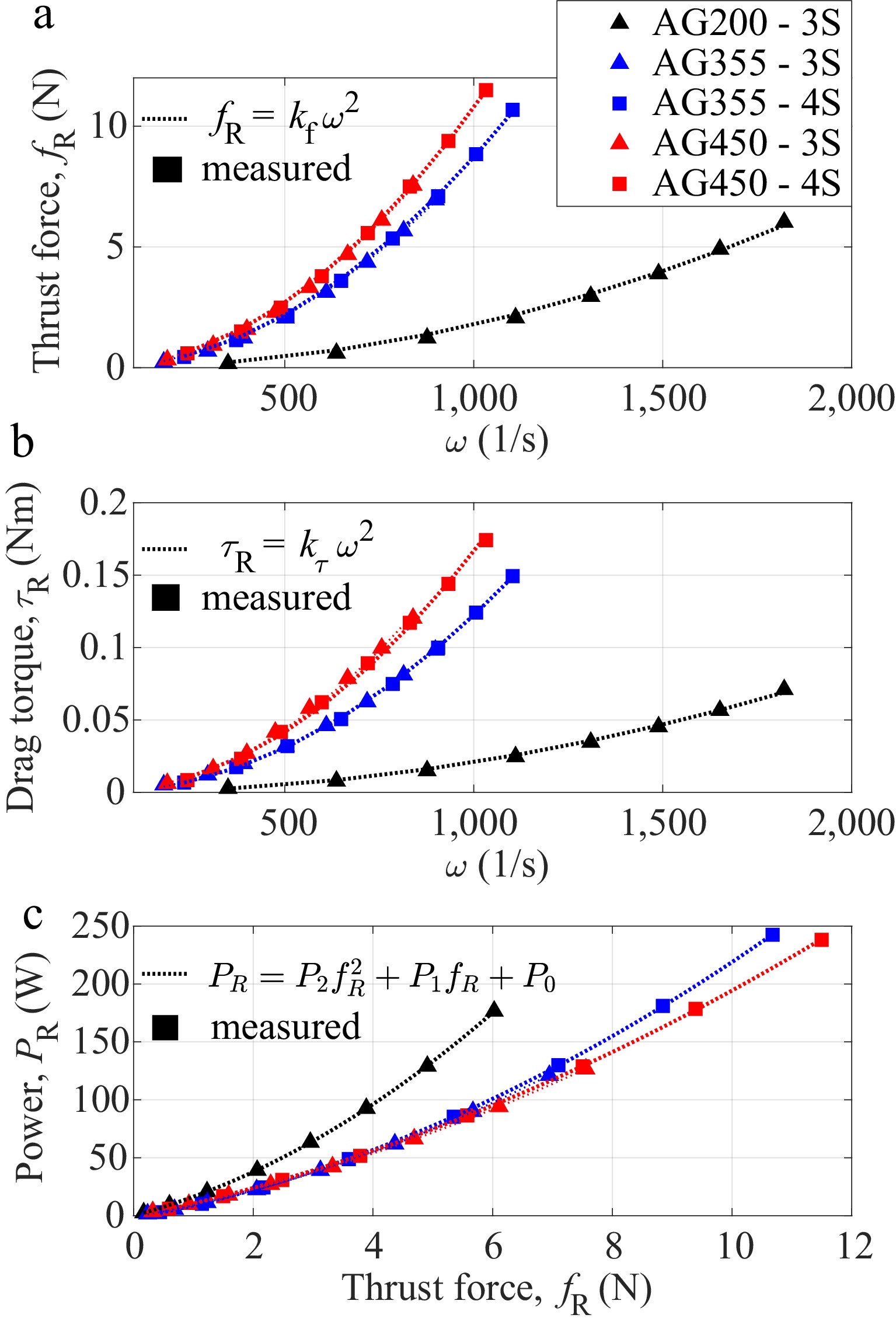
Figure 2.
Experimental characterization for the considered propulsion setups: (a) thrust force as a function of rotor angular velocity; (b) drag torque as a function of rotor angular velocity; (c) electrical power as a function of thrust force. Colored markers represent the experimentally measured data, while the corresponding dotted lines represent the fitted analytical models.
-
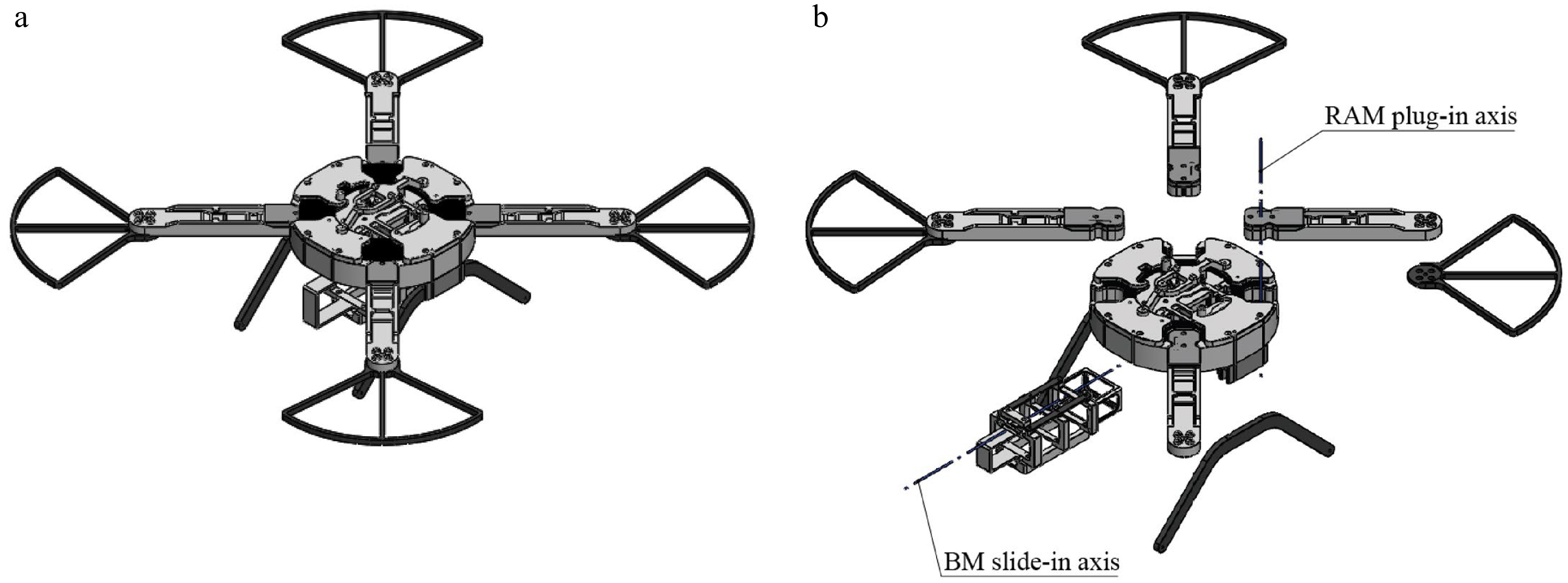
Figure 3.
CAD model of the quadrotor airframe: (a) all modules integrated in a ready-to-fly configuration; (b) exploded view showing the modular separation and landing-gear elements.
-
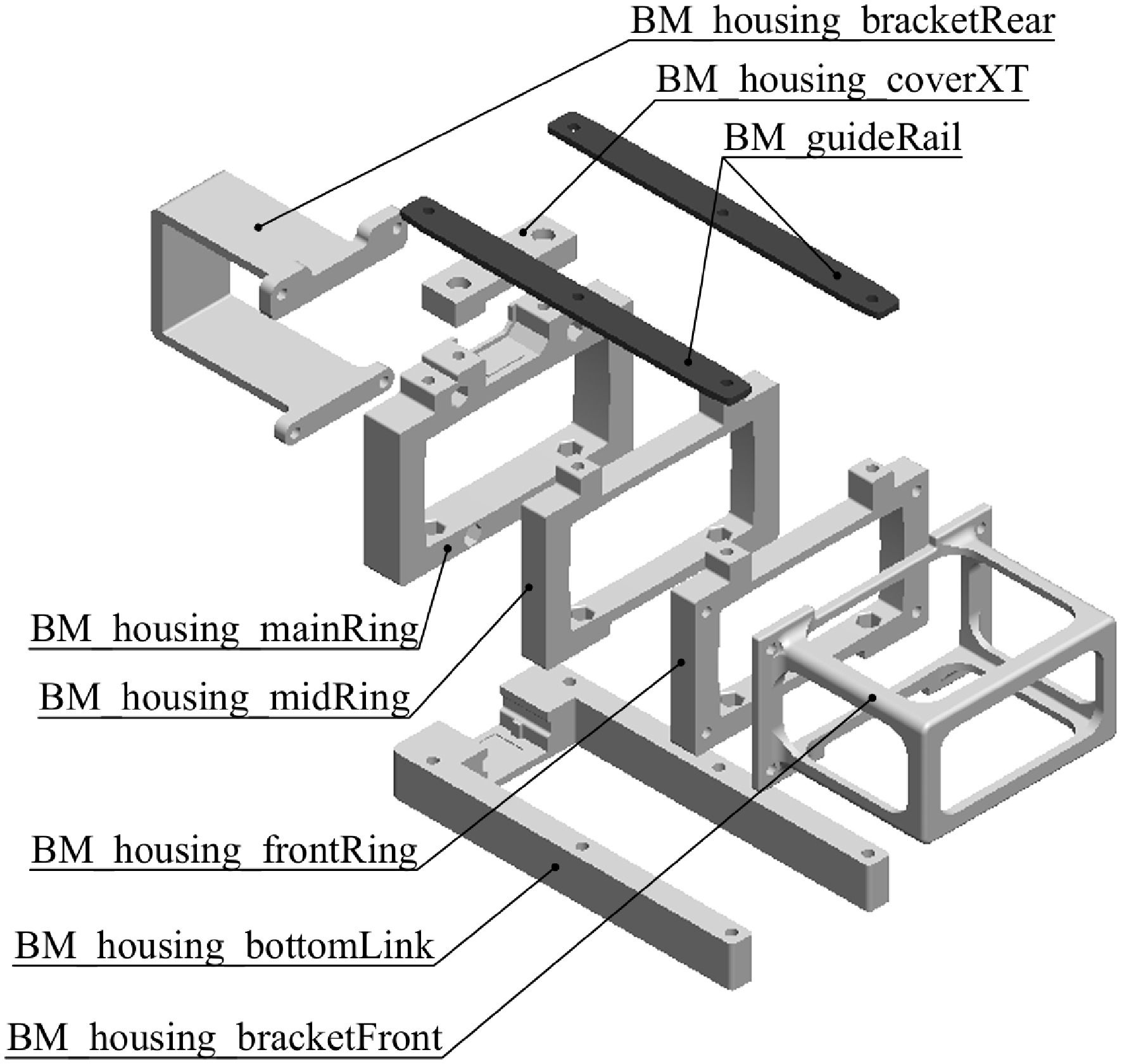
Figure 4.
Exploded view of the parametric BM airframe, consisting of housing and guideRail parts.
-
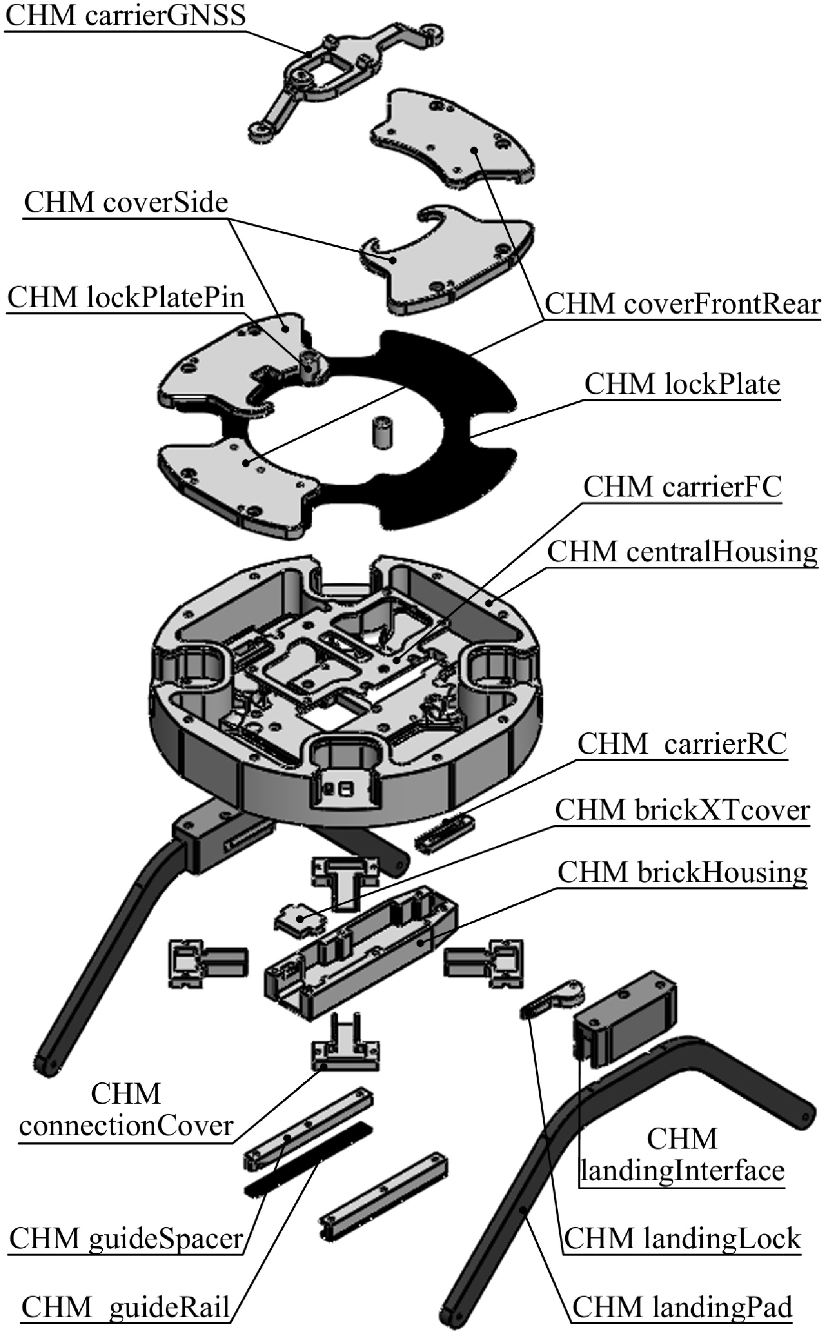
Figure 5.
Exploded view of the CHM airframe assembly.
-
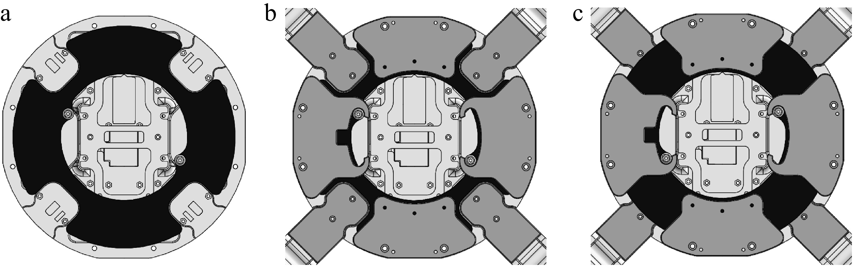
Figure 6.
Illustration of the RAM plug-in sequence: (a) lockPlate in the unlocked position, (b) RAMs inserted into the housing interface, and (c) lockPlate rotated to secure the rotor arms along all three axes.
-
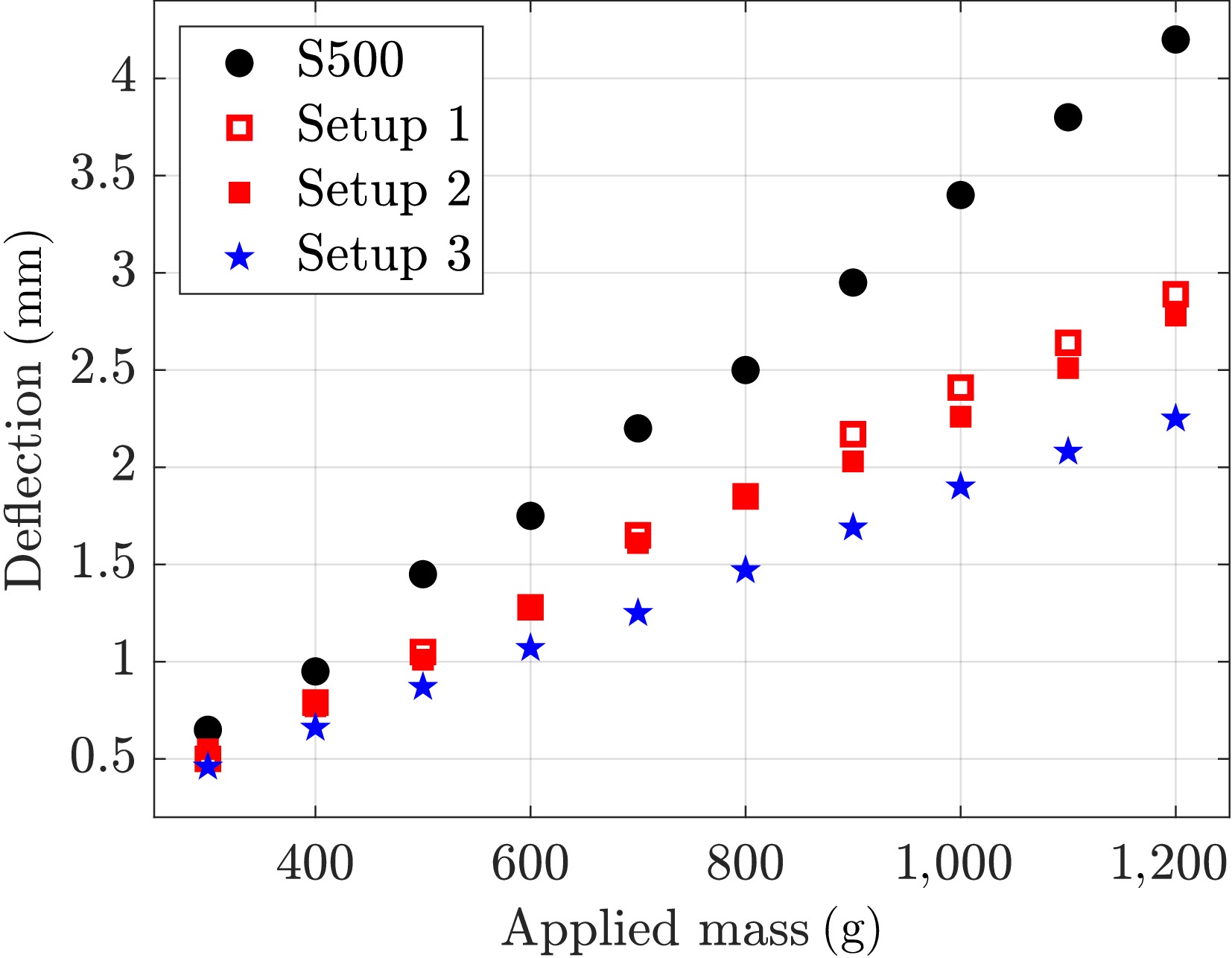
Figure 7.
Summary of load-bearing test results for different rotor arm setups.
-
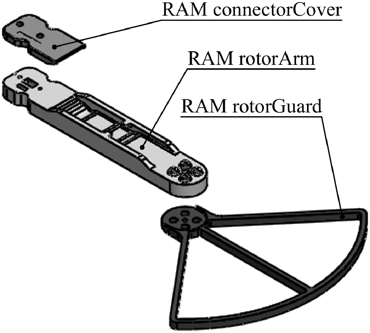
Figure 8.
Exploded view of the parametric RAM airframe.
-
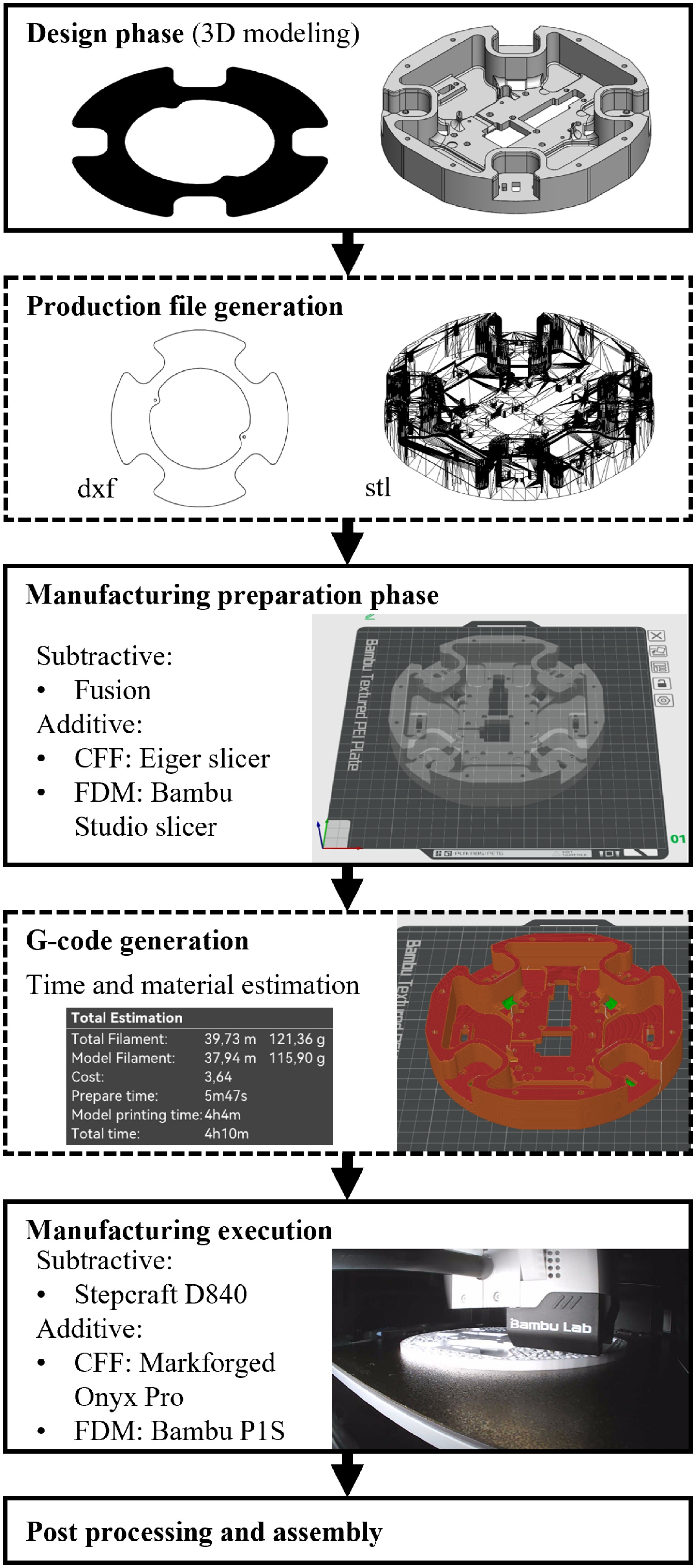
Figure 9.
Overview of the manufacturing framework.
-
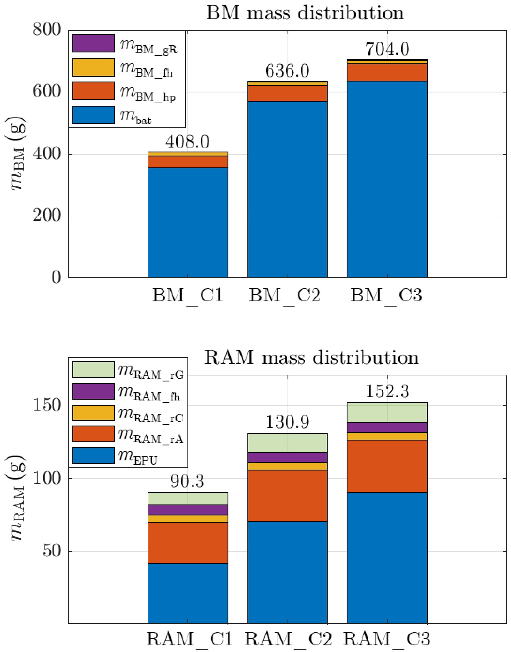
Figure 10.
Comparison of mass distribution for the proposed BM and RAM configurations.
-
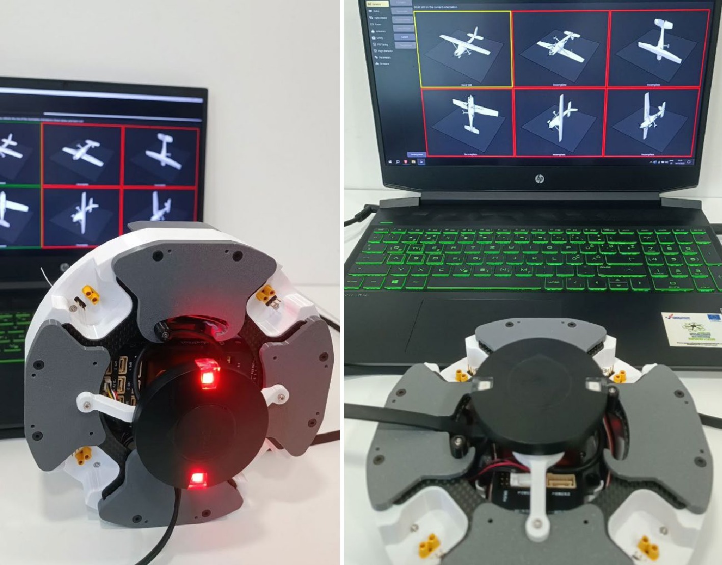
Figure 11.
Assembled CHM airframe with integrated avionics during inertial sensor calibration.
-
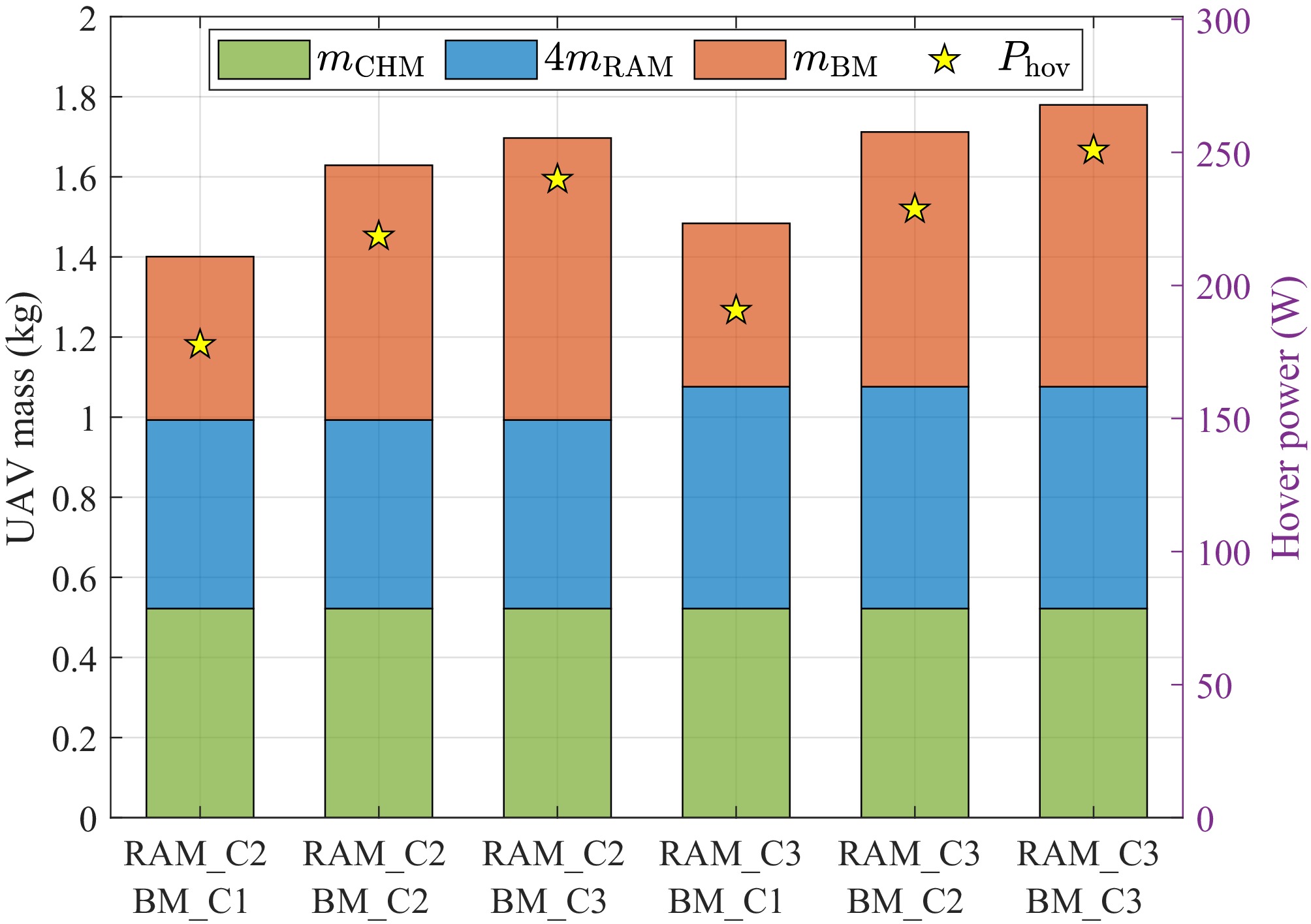
Figure 12.
Comparative overview of the six configurations, showing the total mass and the estimated hover power consumption.
-
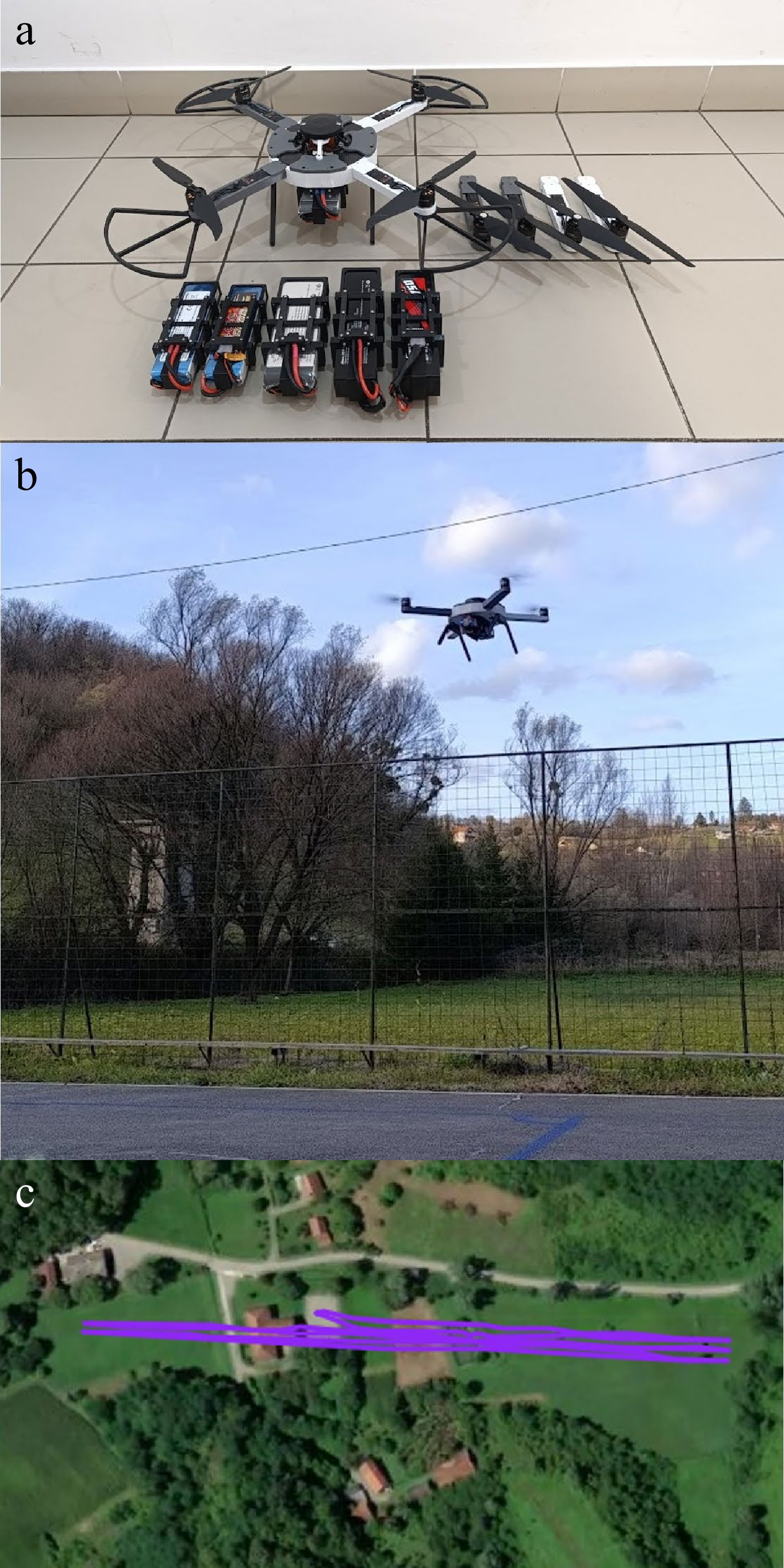
Figure 13.
Tested multirotor UAV platform: (a) fully assembled platform with all modules ready for testing, (b) platform in hovering flight, and (c) flight plan used for the forward-flight experiments.
-
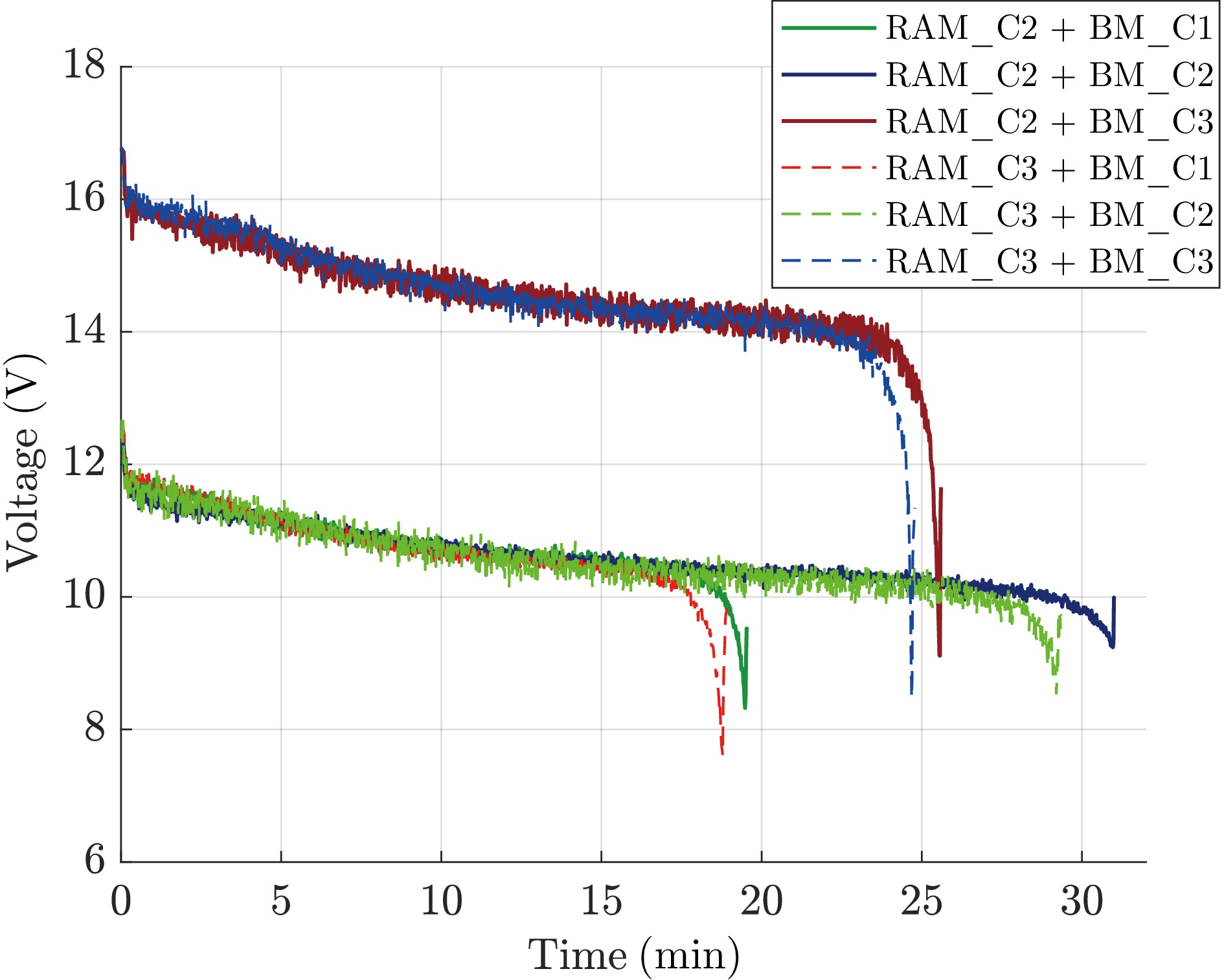
Figure 14.
Voltage profiles over time during hovering for six multirotor UAV configurations, illustrating discharge characteristics and total hovering duration.
-
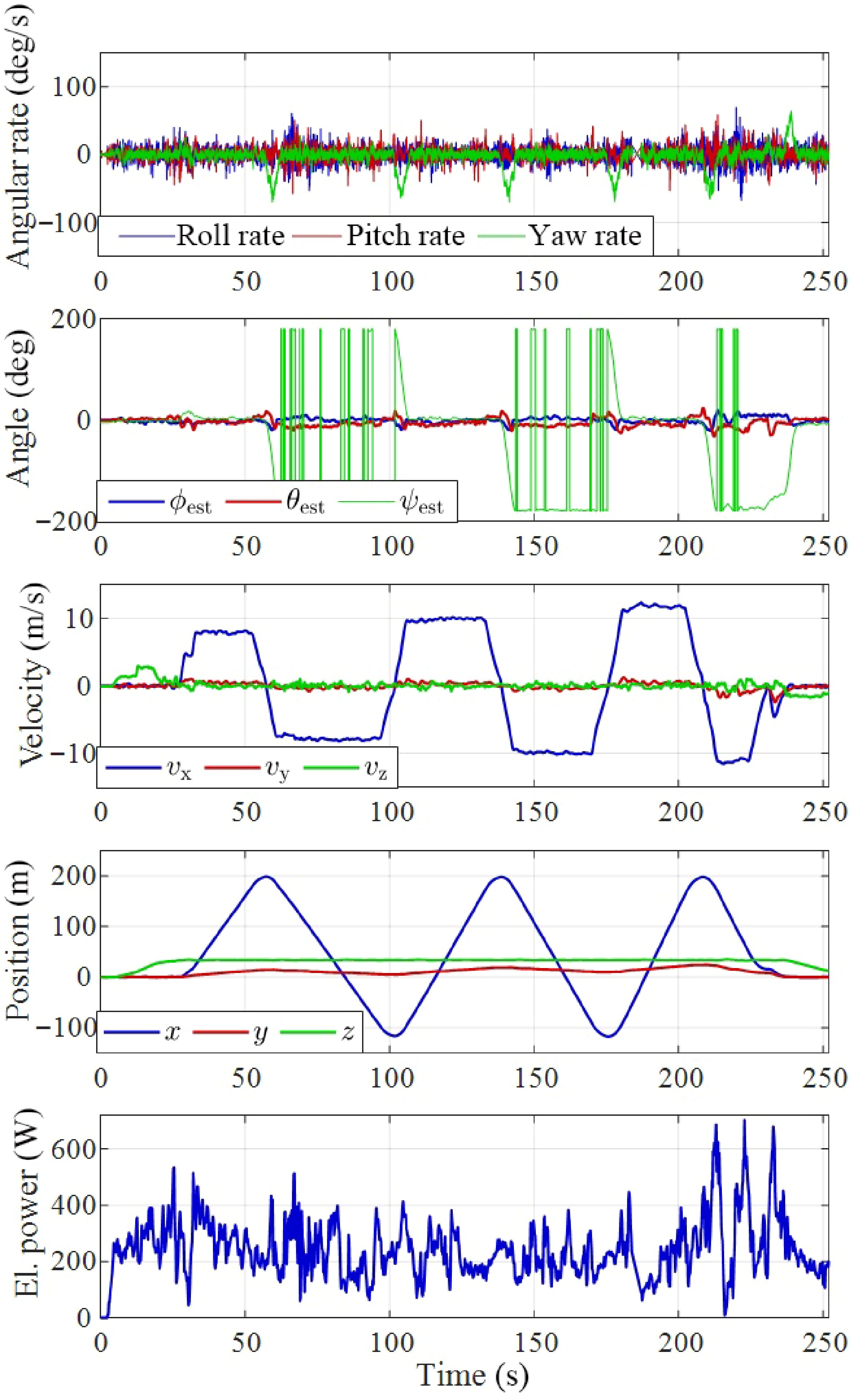
Figure 15.
Flight data for the RAM_C2 + BM_C3 configuration, including angular rates, estimated Euler angles, translational velocity, position, and electrical power, all shown as functions of time.
-
Air Gear set Propeller BLDC ESC Model $ {d}_{\text{p}} $ Model $ {K}_{\text{v}} $ Imax LiPo cell AG200 T6535 6.5" AIR2205 2,000 15 A 2-3S AG355 MF9545 9.5" AIR2213 1,000 20 A 3-4S AG450 T1045 10" AIR2216 880 20 A 3-4S Table 1.
Summary of propulsion kits integrated into the modular UAV platform.
-
BM
config$ {C}_{\text{bat}} $ $ S $ $ {m}_{\text{bat}} $ BM dimensions (mm) $ {m}_{\text{BM}} $ RAM
config$ {d}_{\text{p}} $
(")$ {K}_{\text{v}} $
(rpm/V)$ {m}_{\text{EPU}} $ RAM dimensions (mm) $ {m}_{\text{RAM}} $ L W H L W H BM_C1 5 3 355.2 158 58 54.4 408 RAM_C1 6.5 2,000 42 144 30 15 90.3 BM_C2 10 3 569.2 172 75 58.4 636 RAM_C2 9.5 1,000 70.6 184 30 15 130.9 BM_C3 6.75 4 636.1 187 64 68.4 704 RAM_C3 10 880 90.4 189 30 15 152.3 Table 2.
Summary of the parametrically designed battery module (BM) and rotor arm module (RAM) configurations considered in the proposed modular UAV platform.
-
Module Config ID Part name Print job ID Mass (g) Qty BM Default housing_coverXT 1 1.3 1 BM 4S housing_bottomLink 1 9.3 1 BM C3 housing_mainRing 1 9.6 1 BM C3 housing_midRing 1 7.5 1 BM C3 housing_frontRing 1 7.8 1 BM C3 housing bracketFront 1 8.8 1 BM C3 housing bracketRear 1 8.4 1 RAM CW, CCW connectorCover 1 5.2 2 + 2 RAM C3 (CW, CCW) rotorArm 2 36.1 2 + 2 CHM Default landingInterface 2 11.4 2 CHM Default landingLock 2 0.9 2 CHM Default centralHousing 3 115.9 1 CHM Default connectionCover 4 2.1 4 CHM Default brickHousing 4 12.5 1 CHM Default brickXTcover 4 0.9 1 CHM Default, mirror guideSpacer 4 2.6 1 + 1 CHM Default coverFrontRear 4 8.9 1 + 1 CHM Default, USB slot coverSide 4 9.4, 9.2 1 + 1 CHM Default lockPlatePin 4 0.6 2 CHM PX4 Cube carrierFC 4 4.4 1 CHM TBS Nano carrierRC 4 0.7 1 CHM Here 3 carrierGNSS 4 5.1 1 Table 3.
Overview of FDM printing jobs and associated process parameters.
Figures
(15)
Tables
(3)