












-
Heterogeneous air-ground robotic teams often operate in a forward reconnaissance mode where a UAV advances ahead of a UGV, and cluttered environments can intermittently block visibility and communication, which motivates connectivity constraints that promote reliable coordination, including LOS[1−3]. Such connectivity requirements can lead the UAV to perform energy-intensive maneuvers, including lateral detours, climbs, and frequent speed changes, which increase propulsion power demand and reduce endurance[4], consistent with recent power consumption estimation results showing pronounced power variation under aggressive and time-varying kinematics[5]. Recent MAV studies further emphasize the importance of real-time control, trajectory optimization, and onboard localization for small aerial platforms, including distributed nonlinear MPC for quadrotors, maneuverability-oriented trajectory optimization for fully actuated hexacopters, and moving-horizon UWB localization for small drones[6−8]. As a result, UAV energy becomes a primary bottleneck for long-horizon operation, since the UAV battery capacity is typically far more limited than the UGV energy budget, and the UGV can often serve as a mobile depot for recharging and rendezvous scheduling to mitigate mission disruptions[9,10]. The scenario is illustrated in Fig. 1. Motivated by this asymmetry, we treat the UGV trajectory as provided by a higher-level planner and focus on synthesizing UAV motion that satisfies LOS constraints while minimizing onboard energy, building on recent work in energy-efficient air-ground mission routing and minimum energy planning under periodic connectivity requirements[11,12].
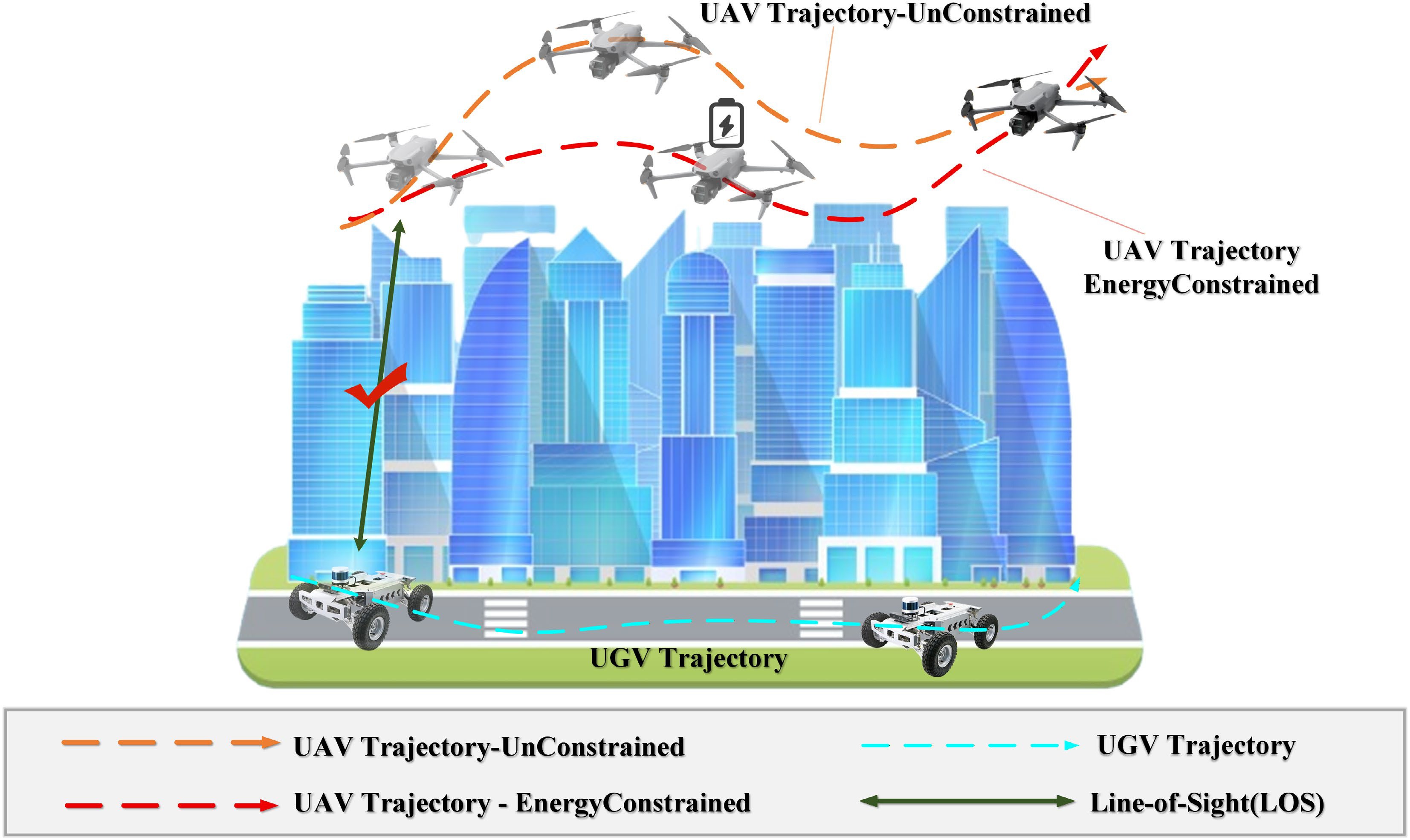
Figure 1.
An illustration of a heterogeneous UAV and UGV systems operating in a cluttered environment. The UAV performs forward reconnaissance while maintaining LOS with the UGV and planning an energy-efficient trajectory toward the goal, accounting for LOS occlusions caused by obstacles.
A substantial literature studies coordination through formation and escort control and collaborative planning. Cheng et al. developed robust finite-time cooperative formation control under uncertainty and actuator faults[13]. Klodt et al. imposed an explicit visibility constraint and showed that visibility requirements can reshape feasible relative motion[14]. Papaioannou et al. incorporated explicit visibility constraints into UAV coverage planning by jointly optimizing guidance and sensing actions, providing a principled visibility-aware CPP formulation[15]. Thelasingha et al. investigated iterative planning for energy-efficient cooperative task site assignments[16]. Wen et al. mapped occlusion risk into online motion modulation to maintain LOS[2]. For urban vehicular communication, ETAR further demonstrates that traffic-light-aware routing can exploit dynamic traffic information to improve routing efficiency and communication reliability[17]. Adaptive reconfiguration via sampling-based reclustering for mMTC[18] is complementary to the motion-level Shield presented in this paper. These studies provide effective coordination mechanisms, but they typically emphasize feasibility, and they do not directly minimize UAV motion energy under an explicit LOS-maintenance requirement when a UAV advances ahead of a UGV to conduct forward reconnaissance.
To clarify how LOS-maintenance requirements in forward reconnaissance can translate into energy-intensive detours and motion modulation, LOS maintenance can be viewed through visibility-aware motion planning, where occlusions are spatial, and the resulting visibility constraints can be non-smooth[19,20]. Wang et al. developed visibility-aware trajectory optimization for aerial tracking by introducing optimization-friendly visibility costs, and further integrated visibility reasoning with additional constraints in cluttered scenes[21,22]. Wang et al. also studied collaborative tracking in urban environments by explicitly accounting for occlusions to improve visibility during motion[23]. Masnavi et al. proposed visibility-aware cooperative navigation that leverages visibility objectives in cluttered settings[24], and Pritzl et al. studied cooperative navigation where a better-equipped platform guides an aerial vehicle through clutter while managing visibility constraints[25]. These works provide practical mechanisms to represent occlusion and incorporate visibility into planning, but they primarily optimize visibility quality for perception and coordination rather than incorporating sampled LOS feasibility as an online motion-control requirement while minimizing UAV motion energy when a UAV advances ahead of a UGV to conduct forward reconnaissance. As a result, the energy impact of LOS-preserving detours, altitude changes, and speed modulation is often not co-optimized with the visibility objective, even though multirotor energy models, practical endurance-estimation methods, and flight-data-based energy-consumption prediction models are available[26−28].
In parallel, multirotor energy modeling and energy-optimal planning have progressed from proxy objectives such as path length to system-level models and speed selection principles. Jacewicz et al. analyzed multirotor energy consumption using nonlinear dynamics and experimental evaluation[29]. Bauersfeld & Scaramuzza derived analytic estimates for range, endurance, and optimal speed with experimental validation[30]. Datsko et al. incorporated optimal speed selection into energy-efficient mission planning and reported substantial reductions in mission energy[31]. Experimental studies on smaller platforms further relate flight conditions to power consumption[32]. This energy bottleneck has also been recognized in larger networked UAV systems; for instance, intelligent UAV caching and energy management in 6G networks studies scalable energy-aware coordination for aerial communication services[33]. However, most energy-focused results are developed without an explicit LOS-maintenance requirement for a moving ground partner, and they do not capture the energy penalties created by detours, climbs, and speed modulation that arise when LOS must be maintained in occlusion-rich environments.
Overall, prior work offers strong tools for cooperative control, visibility-aware planning, and multirotor energy modeling, but it does not provide a unified solution that directly minimizes UAV motion energy under constraint-consistent LOS maintenance in cluttered scenes. Existing approaches often enforce visibility or connectivity requirements without explicitly minimizing the UAV propulsion energy required to satisfy them, or they optimize energy without representing LOS constraints induced by complex occlusions. This paper addresses this gap by focusing on energy-minimizing UAV motion under LOS-aware feasibility enforcement when a UAV advances ahead of a UGV to conduct forward reconnaissance. The proposed Shield enforces sampled one-step feasibility when the admissible velocity set is non-empty and switches to a recovery action when the sampled constraints are temporarily infeasible.
To address the limited mission endurance caused by high propulsion energy demand in forward-reconnaissance UAV–UGV teams, this paper develops an energy-efficient and constraint-consistent control framework for cluttered environments. The framework reduces UAV propulsion energy while maintaining LOS connectivity. A learning-based controller outputs nominal velocity commands that are corrected by a Shield safety filter into executed velocities that respect safety-critical requirements, and all state propagation, energy accounting, and performance evaluation are defined on the executed shielded velocity to ensure that energy reduction is achieved in the closed loop. This design ensures that reduced UAV energy consumption translates into longer effective mission time under practical feasibility enforcement in deployment. The main contributions are summarized as follows:
● an energy-efficient motion control framework that integrates SAC-based nominal velocity generation with a real-time Shield to reduce UAV energy consumption while maintaining LOS connectivity and feasibility in cluttered environments;
● a propulsion-energy-aware shielded learning formulation for rotary-wing UAVs, built on a standard rotary-wing propulsion-power surrogate, that evaluates energy from the executed velocity and incorporates acceleration-related motion variation through executed-velocity smoothing and acceleration-sensitive model comparison;
● a real-time LOS connectivity evaluation method that integrates obstacle inflation with LOS segment sampling and applies smooth minimum aggregation to yield a continuous, differentiable LOS clearance margin for characterizing geometric occlusion risk.
The remainder of this paper is organized as follows. The proposed methodology and its practical implementation are described first, followed by the experimental setup and main results. The findings are then discussed, and the paper concludes with several directions for future research.
-
As illustrated in Fig. 2, the proposed framework forms a closed loop among the Environment module, the Energy-Efficient Constraint-Consistent Shielded Reinforcement Learning module, and the Task module.
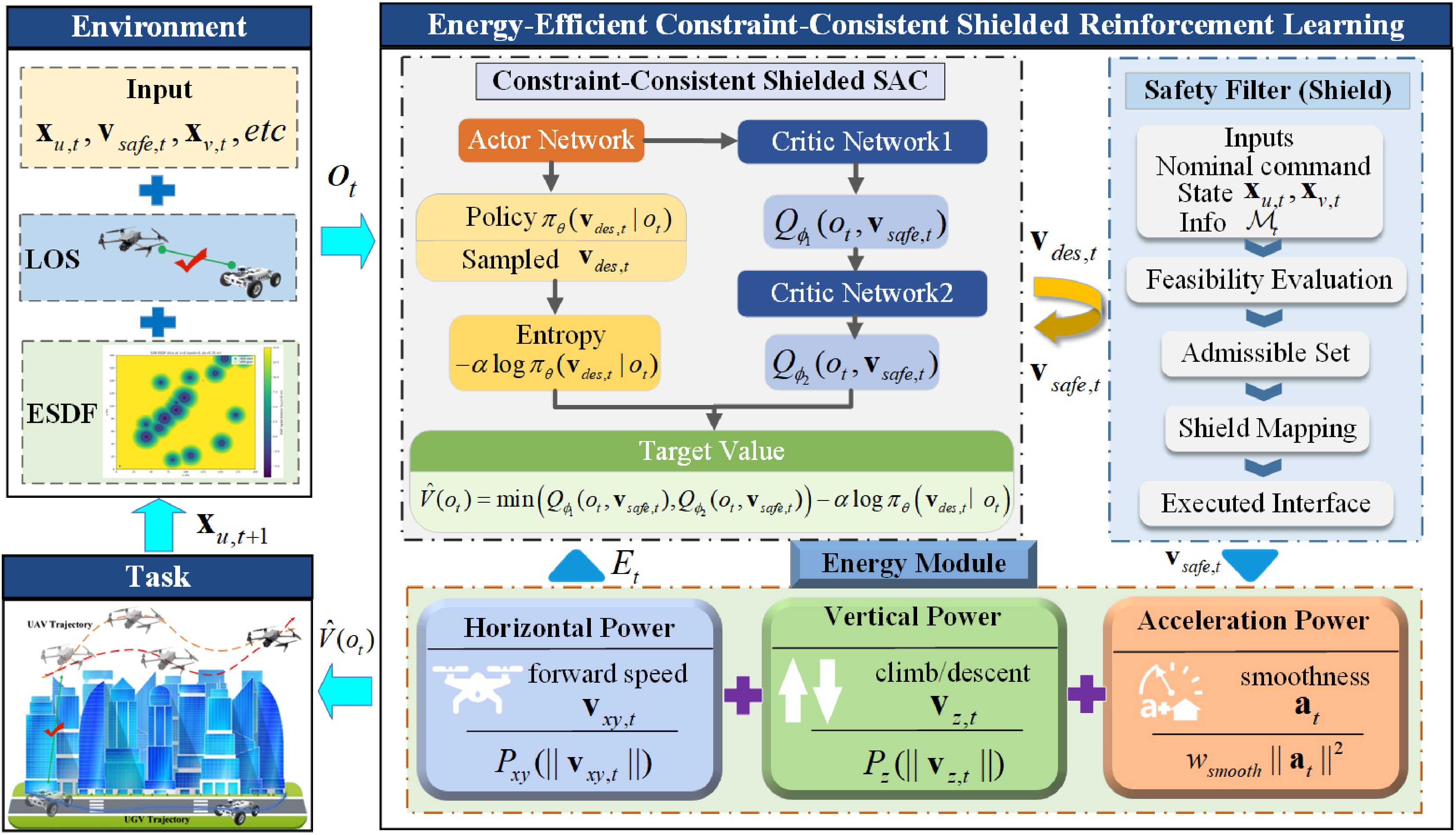
Figure 2.
Framework of the proposed method.
At each time step, the Environment provides the current observation to the Learning module, which generates a nominal UAV velocity command. The Safety Filter, referred to as the shield, checks this command against safety and connectivity requirements and outputs the executed velocity. State propagation, energy accounting, reward evaluation, and termination checks are all computed from this shielded velocity rather than from the nominal command. Finally, the Task module updates the system and returns the next-state information to the Environment, completing the closed loop. This design keeps training and execution consistent under constraints and makes shield intervention explicitly measurable.
Problem formulation and kinematics
-
We consider a heterogeneous UAV–UGV team operating in a cluttered environment
$ \Omega\subset\mathbb{R}^{3} $ In this work, the UGV trajectory is treated as an exogenous reference provided by a higher-level ground-vehicle or mission planner; thus, the proposed method focuses on the UAV-side motion-control problem. Joint UAV–UGV trajectory optimization, dynamic UGV replanning, and multi-agent task allocation are beyond the scope of the present study.
The control interface is velocity-based. At each time step, a policy generates a nominal velocity command, which is subsequently processed by a Safety Filter, denoted as the Shield, into an executed velocity. When the state-dependent admissible velocity set is non-empty, the Shield selects an executed command satisfying the one-step feasibility requirements. When no candidate velocity satisfies all requirements simultaneously, the Shield applies a recovery rule that prioritizes restoring LOS, obstacle-clearance, and forward-reconnaissance margins. Both state propagation and energy accounting are defined using the executed velocity, ensuring consistent evaluation when the nominal command is modified before execution. The Shield defines the actual control applied to the system and therefore the evaluation interface of the closed loop.
Time is discretized as
$ t=0,1,\ldots,T-1 $ $ \Delta t>0 $ $ {\bf{x}}_{u,t},{\bf{x}}_{v,t}\in\mathbb{R}^3 $ $ z_{v,t}\equiv 0 $ $ {\cal{X}}_u=\mathbb{R}^3,\qquad {\cal{X}}_v=\{{\bf{x}}\in\mathbb{R}^3\mid z=0\}, $ (1) $ {\cal{X}}_u $ $ {\cal{X}}_v $ Let:
$ P_{xy}={\rm{diag}}(1,1,0),\qquad {\bf{e}}_z=[0,0,1]^{\top} $ (2) denote the horizontal projection operator and the vertical unit vector, respectively.
Forward reconnaissance is formalized through an ahead requirement relative to the UGV in the horizontal projection. Using the horizontal projection operator
$ P_{xy} $ $ \hat{{\bf{t}}}_{v,t} $ $ {\bf{x}}_{v,g} $ $ \hat{{\bf{t}}}_{v,t}= \begin{cases} \dfrac{P_{xy}({\bf{x}}_{v,g}-{\bf{x}}_{v,t})}{\left\|P_{xy}({\bf{x}}_{v,g}-{\bf{x}}_{v,t})\right\|_2}, & \left\|P_{xy}({\bf{x}}_{v,g}-{\bf{x}}_{v,t})\right\|_2 \gt 0,\\ [1,0,0]^{\top}, & {\rm{otherwise}}, \end{cases} $ (3) where,
$ \|\cdot\|_2 $ $ s_{f,t} = \left(\hat{{\bf{t}}}_{v,t}\right)^{\top} P_{xy}\left({\bf{x}}_{u,t}-{\bf{x}}_{v,t}\right), $ (4) $ s_{f,t} $ $ s_{f,t}\ge s_{\min}, $ (5) where,
$ s_{\min}>0 $ $ \sigma_{f,t} = \max(0,s_{\min}-s_{f,t}), $ (6) where,
$ \sigma_{f,t}=0 $ $ \sigma_{f,t}>0 $ Minimizing energy alone may lead to a trivial behavior where the UAV reduces motion to save power. To ensure a persistent task reference that advances with the UGV, we introduce a moving look-ahead reference point:
$ {\bf{p}}_{{\rm{ref}},t} = {\bf{x}}_{v,t}+d_{{\rm{ahead}}}\hat{{\bf{t}}}_{v,t}, $ (7) where,
$ d_{{\rm{ahead}}}>0 $ $ {\bf{p}}_{{\rm{ref}},t} $ At each step t, the policy outputs a nominal UAV velocity command
$ {\bf{v}}_{{\rm{des}},t}\in\mathbb{R}^{3} $ $ {\bf{v}}_{{\rm{des}},t} $ $ {\bf{v}}_{{\rm{safe}},t} $ $ {\bf{v}}_{{\rm{safe}},t} = {\cal{S}} \left( {\bf{v}}_{{\rm{des}},t}, {\bf{x}}_{u,t}, {\bf{x}}_{v,t}, {\cal{M}}_{t} \right), $ (8) where,
$ {\cal{M}}_{t} $ $ {\bf{v}}_{v,t} $ $ {\cal{M}}_{t} $ $ {\cal{M}}_{t} $ The Shield is implemented as a one-step candidate-projection filter. Let:
$ {\cal{U}} = \left\{ {\bf{v}}\in\mathbb{R}^{3} \ \middle|\ \|{\bf{v}}\|_2\le v_{\max},\ |v_z|\le v_{z,\max} \right\} $ (9) denote the UAV velocity envelope. To construct candidate velocities, define a horizontal steering direction:
$ {\bf{e}}^{\perp}_{t} = \begin{cases} \dfrac{{\bf{e}}_z\times P_{xy}{\bf{v}}_{{\rm{des}},t}} {\left\|P_{xy}{\bf{v}}_{{\rm{des}},t}\right\|_2}, & \left\|P_{xy}{\bf{v}}_{{\rm{des}},t}\right\|_2 \gt 0,\\ [0,1,0]^{\top}, & {\rm{otherwise}}. \end{cases} $ (10) At each time step, a finite candidate set
$ {\cal{C}}_t=\{{\bf{v}}_{t}^{k}\}_{k=1}^{K} $ $ {\cal{C}}_t = \left\{ \Pi_{{\cal{U}}} \left( \alpha_m {\bf{v}}_{{\rm{des}},t} + \beta_n {\bf{e}}^{\perp}_{t} + \gamma_q {\bf{e}}_z \right) \ \middle|\ \alpha_m\in{\cal{A}},\ \beta_n\in{\cal{B}},\ \gamma_q\in{\cal{G}} \right\} \cup \{\mathbf{0}\}. $ (11) Here,
$ {\cal{A}} $ $ {\cal{B}} $ $ {\cal{G}} $ $ \Pi_{{\cal{U}}}(\cdot) $ $ {\cal{U}} $ For each candidate
$ {\bf{v}}\in{\cal{C}}_t $ $ \hat{{\bf{x}}}_{u,t+1}({\bf{v}}) = {\bf{x}}_{u,t}+{\bf{v}}\Delta t, \qquad \hat{{\bf{x}}}_{v,t+1} = {\bf{x}}_{v,t}+{\bf{v}}_{v,t}\Delta t . $ (12) The UGV prediction
$ \hat{{\bf{x}}}_{v,t+1} $ $ {\bf{v}}_{v,t} $ Using the predicted states, the Shield evaluates the predicted ahead distance, obstacle signed clearance, and LOS signed feasibility margin:
$ \hat{s}_{f,t+1}({\bf{v}}),\qquad \hat{d}_{{\rm{obs}},t+1}({\bf{v}}),\qquad \hat{g}_{{\rm{LOS}},t+1}({\bf{v}}). $ (13) Here,
$ \hat{s}_{f,t+1}({\bf{v}}) $ $ \hat{{\bf{x}}}_{u,t+1}({\bf{v}}) $ $ \hat{{\bf{x}}}_{v,t+1} $ $ \hat{d}_{{\rm{obs}},t+1}({\bf{v}}) $ $ \hat{{\bf{x}}}_{u,t+1}({\bf{v}}) $ $ \hat{g}_{{\rm{LOS}},t+1}({\bf{v}}) $ $ \hat{{\bf{x}}}_{u,t+1}({\bf{v}}) $ $ \hat{{\bf{x}}}_{v,t+1} $ The state-dependent admissible velocity set is then constructed as:
$ {\cal{V}}_{t} = \left\{ {\bf{v}}\in{\cal{C}}_t \ \middle|\ \begin{array}{l} {\bf{v}}\in{\cal{U}},\\ z_{\min}\le \hat{z}_{u,t+1}({\bf{v}})\le z_{\max},\\ \hat{d}_{{\rm{obs}},t+1}({\bf{v}})\ge m_{{\rm{col}}},\\ \hat{g}_{{\rm{LOS}},t+1}({\bf{v}})\ge \varepsilon_{{\rm{LOS}}},\\ \hat{s}_{f,t+1}({\bf{v}})\ge s_{\min} \end{array} \right\}. $ (14) Here,
$ z_{\min} $ $ z_{\max} $ $ m_{{\rm{col}}} $ $ \varepsilon_{{\rm{LOS}}} $ $ s_{\min} $ $ {\cal{C}}_t $ $ {\cal{V}}_t $ $ \hat d_{{\rm{obs}},t+1}({\bf{v}}) $ $ \hat g_{{\rm{LOS}},t+1}({\bf{v}}) $ $ \hat s_{f,t+1}({\bf{v}}) $ $ {\cal{V}}_t $ When
$ {\cal{V}}_{t}\neq\varnothing $ $ {\bf{v}}_{{\rm{safe}},t} = \arg\min_{{\bf{v}}\in{\cal{V}}_{t}} \left[ \left\|{\bf{v}}-{\bf{v}}_{{\rm{des}},t}\right\|_2^2 + \lambda_E \widehat{E}_{t}({\bf{v}}) + \lambda_{\Delta v} \left\|{\bf{v}}-{\bf{v}}_{{\rm{safe}},t-1}\right\|_2^2 \right]. $ (15) Here,
$ \widehat{E}_{t}({\bf{v}}) $ $ {\bf{v}} $ $ \lambda_E,\lambda_{\Delta v}\ge 0 $ $ t=0 $ $ {\bf{v}}_{{\rm{safe}},t-1} $ $ \mathbf{0} $ When
$ {\cal{V}}_{t}=\varnothing $ $ {\cal{C}}_t $ $\begin{split} {\bf{v}}_{{\rm{safe}},t} =\;& \arg\max_{{\bf{v}}\in{\cal{C}}_t} \Big[ \eta_{{\rm{LOS}}}\hat{g}_{{\rm{LOS}},t+1}({\bf{v}}) + \eta_{{\rm{obs}}}\hat{d}_{{\rm{obs}},t+1}({\bf{v}}) + \eta_f\hat{s}_{f,t+1}({\bf{v}}) \\& - \eta_v\|{\bf{v}}\|_2^2 - \eta_{\Delta v} \left\|{\bf{v}}-{\bf{v}}_{{\rm{safe}},t-1}\right\|_2^2 \Big].\end{split} $ (16) Here,
$ \eta_{{\rm{LOS}}},\eta_{{\rm{obs}}},\eta_f,\eta_v,\eta_{\Delta v}\ge 0 $ Therefore, when
$ {\cal{V}}_t \neq \varnothing $ $ {\cal{V}}_t = \varnothing $ With velocity-level kinematics, the system state is propagated by forward Euler integration:
$ {\bf{x}}_{u,t+1}={\bf{x}}_{u,t}+{\bf{v}}_{{\rm{safe}},t}\,\Delta t,\qquad {\bf{x}}_{v,t+1}={\bf{x}}_{v,t}+{\bf{v}}_{v,t}\,\Delta t, $ (17) where,
$ {\bf{v}}_{{\rm{safe}},t} $ $ {\bf{v}}_{v,t} $ $ \Delta t $ $ {\bf{v}}_{{\rm{safe}},t} $ $ {\bf{v}}_{{\rm{safe}},t} $ $ {\bf{v}}_{{\rm{des}},t} $ Finally, to make the effect of feasibility enforcement explicit and to prevent attributing performance gains to the Shield itself, we quantify Shield intervention by:
$ I_t = \left\| {\bf{v}}_{{\rm{safe}},t} - {\bf{v}}_{{\rm{des}},t} \right\|_2, $ (18) which will be used both as a diagnostic metric and as a regularizer in the learning objective to discourage policies that rely on frequent post-corrections.
LOS geometry and risk metrics
-
Let
$ \Omega\subset\mathbb{R}^3 $ $ {\cal{O}}=\{{\cal{O}}_i\}_{i=1}^{N} $ $ {\cal{O}}_i $ $ {\bf{o}}_i=[x_i,y_i,z_i]^{\top} $ $ R_i>0 $ $ H_i>0 $ $ [z_i,\;z_i+H_i] $ $ z_i>0 $ The finite-cylinder obstacle model is adopted as a tractable abstraction of dominant LOS occluders in the considered simulation environment. This abstraction allows us to isolate and evaluate the coupling among UAV propulsion energy, LOS obstruction, altitude adjustment, and obstacle avoidance. However, it does not fully represent all urban occlusion geometries, such as irregular building facades, balconies, overhangs, vegetation, or detailed mesh structures.
To improve robustness to localization and mapping uncertainty, we introduce a nonnegative inflation margin
$ b\ge 0 $ $ \tilde{R}_i \triangleq R_i + b , $ (19) where,
$ \tilde{R}_i $ $ b=0 $ We define the clearance of a query point as its shortest Euclidean distance to the obstacle boundary. The corresponding signed distance is positive in free space and negative inside the inflated occupied set. Let
$ \tilde{{\cal{O}}}=\bigcup_{i=1}^{N}\tilde{{\cal{O}}}_i $ $ \partial\tilde{{\cal{O}}} $ $ {\bf{p}}\in\Omega $ $ d_{{\rm{ESDF}}}({\bf{p}}) \triangleq \begin{cases} \min\limits_{{\bf{q}}\in\partial\tilde{{\cal{O}}}}\|{\bf{p}}-{\bf{q}}\|_2, & {\bf{p}}\in \Omega\setminus \tilde{{\cal{O}}},\\ -\min\limits_{{\bf{q}}\in\partial\tilde{{\cal{O}}}}\|{\bf{p}}-{\bf{q}}\|_2, & {\bf{p}}\in \tilde{{\cal{O}}} , \end{cases} $ (20) where,
$ \|\cdot\|_2 $ $ d_{{\rm{ESDF}}}({\bf{p}})>0 $ $ d_{{\rm{ESDF}}}({\bf{p}})<0 $ $ |d_{{\rm{ESDF}}}({\bf{p}})| $ The UAV obstacle signed clearance at time t is defined as:
$ d_{{\rm{obs}},t} \triangleq d_{{\rm{ESDF}}}({\bf{x}}_{u,t}). $ (21) Correspondingly, the predicted obstacle signed clearance used by the Shield is
$ \hat{d}_{{\rm{obs}},t+1}({\bf{v}}) = d_{{\rm{ESDF}}}(\hat{{\bf{x}}}_{u,t+1}({\bf{v}})) $ For LOS assessment at discrete time t, given the UAV and UGV positions
$ {\bf{x}}_{u,t} $ $ {\bf{x}}_{v,t} $ $ {\cal{L}}_{t}= \left\{ {\bf{x}}_{u,t}+\lambda\bigl({\bf{x}}_{v,t}-{\bf{x}}_{u,t}\bigr) \ \middle|\ \lambda\in[0,1] \right\}. $ (22) To obtain a computable approximation of the segment-to-obstacle relation, we uniformly sample
$ S\ge 2 $ $ {\cal{L}}_{t} $ $ {\bf{p}}(s_\ell)= {\bf{x}}_{u,t}+s_\ell\bigl({\bf{x}}_{v,t}-{\bf{x}}_{u,t}\bigr), \qquad s_\ell=\dfrac{\ell-1}{S-1},\quad \ell=1,\ldots,S , $ (23) where,
$ {\bf{p}}(s_\ell)=[p_x,p_y,p_z]^{\top} $ $ \ell $ For each sampled point
$ {\bf{p}}(s_\ell)=[p_x,p_y,p_z]^{\top} $ $ \tilde{R}_i $ $ \Delta_{i,r}(s_\ell) = \sqrt{(p_x-x_i)^2+(p_y-y_i)^2} - \tilde{R}_i , $ (24) and the vertical separation to the axial interval:
$ \Delta_{i,z}(s_\ell) = \max \left(z_i-p_z,\ p_z-(z_i+H_i),\ 0\right). $ (25) The radial margin
$ \Delta_{i,r}(s_\ell) $ $ \Delta_{i,r}(s_\ell) $ The unsigned point-wise proximity surrogate is defined as:
$ \Delta_i^+(s_\ell) = \sqrt{ \bigl[\Delta_{i,r}(s_\ell)\bigr]_+^{2} + \bigl[\Delta_{i,z}(s_\ell)\bigr]_+^{2}}, \qquad [a]_+\triangleq\max(a,0). $ (26) The quantity
$ \Delta_i^{+}(s_\ell) $ $ \Delta_i^{+}(s_\ell)=0 $ For feasibility checking, we further introduce a sign-preserving signed distance to the inflated finite cylinder. Let:
$ \rho_i({\bf{p}}) = \sqrt{(p_x-x_i)^2+(p_y-y_i)^2}, \qquad c_{z,i}=z_i+\dfrac{H_i}{2}, \qquad h_i=\dfrac{H_i}{2}. $ (27) Define:
$ {\bf{q}}_i({\bf{p}}) = \begin{bmatrix} \rho_i({\bf{p}})-\tilde{R}_i\\ |p_z-c_{z,i}|-h_i \end{bmatrix}. $ (28) The signed distance to the inflated finite cylinder is then computed as:
$ d_i^{{\rm{cyl}}}({\bf{p}}) = \left\| \max \left({\bf{q}}_i({\bf{p}}),\mathbf{0}\right) \right\|_2 + \min \left( \max \left(q_{i,1}({\bf{p}}),q_{i,2}({\bf{p}})\right), 0 \right), $ (29) where, the maximum between vectors is taken component-wise. This signed distance is positive outside the inflated cylinder, zero on its boundary, and negative inside it. Hence, it preserves the penetration sign required for LOS feasibility assessment.
To avoid the non-smoothness of a hard minimum, we approximate the minimum operator using a soft-min operator. For a vector
$ {\bf{v}}=[v_1,\ldots,v_M] $ $ {\rm{softmin}}_{\tau}({\bf{v}}) \triangleq -\tau \log \left( \dfrac{1}{M} \sum\limits_{m=1}^{M} \exp \left(-\dfrac{v_m}{\tau}\right) \right), \qquad \tau \gt 0, $ (30) which approaches
$ \min_m v_m $ $ \tau\to 0^{+} $ Applying Eq. (30) to the unsigned proximity values gives the obstacle-wise minimum proximity surrogate:
$ \Delta_{i,+}^{\min} \approx {\rm{softmin}}_{\tau} \left( \{\Delta_i^+(s_\ell)\}_{\ell=1}^{S} \right). $ (31) The global unsigned LOS proximity surrogate is then defined as:
$ d_{{\rm{LOS}},t} \approx {\rm{softmin}}_{\tau} \left( \{\Delta_{i,+}^{\min}\}_{i=1}^{N} \right). $ (32) The quantity
$ d_{{\rm{LOS}},t} $ $ d_{{\rm{LOS}},t} $ In parallel, applying the soft-min aggregation to the signed cylinder distance yields the signed LOS feasibility margin:
$ g_{{\rm{LOS}},t} \approx {\rm{softmin}}_{\tau} \left( \left\{ d_i^{{\rm{cyl}}} \left({\bf{p}}(s_\ell)\right) \right\}_{i=1,\ldots,N;\ \ell=1,\ldots,S} \right). $ (33) The condition
$ g_{{\rm{LOS}},t}>0 $ $ g_{{\rm{LOS}},t}\le 0 $ $ g_{{\rm{LOS}},t} $ Finally, we map the unsigned LOS proximity surrogate
$ d_{{\rm{LOS}},t} $ $ g_{{\rm{LOS}},t} $ $ \phi_{{\rm{LOS}},t}\in[0,1] $ $ d_{{\rm{safe}}}>d_{{\rm{crit}}}\ge 0 $ $ p\ge 1 $ $ \phi_{{\rm{LOS}},t} = \begin{cases} 1, & g_{{\rm{LOS}},t}\le 0,\\ 0, & g_{{\rm{LOS}},t} \gt 0\ {\rm{and}}\ d_{{\rm{LOS}},t}\ge d_{{\rm{safe}}},\\ 1, & g_{{\rm{LOS}},t} \gt 0\ {\rm{and}}\ d_{{\rm{LOS}},t}\le d_{{\rm{crit}}},\\ \left(\bar{\xi}_t\right)^p, & g_{{\rm{LOS}},t} \gt 0\ {\rm{and}}\ d_{{\rm{crit}}} \lt d_{{\rm{LOS}},t} \lt d_{{\rm{safe}}}, \end{cases} $ (34) where:
$ \xi_t = \dfrac{d_{{\rm{safe}}}-d_{{\rm{LOS}},t}} {d_{{\rm{safe}}}-d_{{\rm{crit}}}} \in(0,1), $ (35) and
$ \bar{\xi}_t $ $ C^1 $ $ \bar{\xi}_t = (\xi_t)^2(3-2\xi_t). $ (36) The quantity
$ d_{{\rm{LOS}},t} $ $ g_{{\rm{LOS}},t}\le 0 $ Energy-efficient constraint-consistent learning
-
Onboard battery capacity is limited, making UAV propulsion energy a key determinant of mission endurance. In contrast, the UGV typically has larger energy reserves, and its energy usage is not the dominant bottleneck in our setting. We therefore model energy consumption only for the UAV and use it as a physically grounded metric for both learning and evaluation.
The formulation is constraint-consistent: the policy is optimized with respect to the feasibility-adjusted action that is actually executed, and the objective explicitly regularizes the discrepancy between the proposed action and the feasible action. This reduces the mismatch between the optimization objective during learning and the behavior induced at deployment under safety and connectivity constraints.
For energy accounting, the UAV velocity at time step t is the executed velocity
$ {\bf{v}}_{t}\equiv{\bf{v}}_{{\rm{safe}},t} $ $ P_{xy} $ $ {\bf{v}}_{xy,t} \triangleq P_{xy}{\bf{v}}_{{\rm{safe}},t},\qquad v_{z,t} \triangleq {\bf{e}}_z^\top {\bf{v}}_{{\rm{safe}},t}. $ (37) To avoid overloading
$ P_{xy} $ $ P_{{\rm{hor}}}(\cdot) $ $ \begin{aligned} P_{{\rm{hor}}} \left(\|{\bf{v}}_{xy,t}\|_2\right) &= P_0 \left(1+\dfrac{3\|{\bf{v}}_{xy,t}\|_2^2}{U_{{\rm{tip}}}^2}\right) \\ &\quad + P_i \left( \sqrt{1+\dfrac{\|{\bf{v}}_{xy,t}\|_2^4}{4v_0^4}} - \dfrac{\|{\bf{v}}_{xy,t}\|_2^2}{2v_0^2} \right)^{\dfrac{1}{2}} \\ &\quad + \dfrac{1}{2}d_0\rho sA\,\|{\bf{v}}_{xy,t}\|_2^3 . \end{aligned} $ (38) where,
$ P_0 $ $ P_i $ $ U_{{\rm{tip}}} $ $ v_0 $ $ d_0 $ To account for three-dimensional maneuvers, we approximate the vertical power by a linear equivalent model:
$ P_z(v_{z,t}) = k_{{\rm{climb}}}\max(0, v_{z,t}) + k_{{\rm{desc}}}\max(0, -v_{z,t}), $ (39) where,
$ k_{{\rm{climb}}} $ $ k_{{\rm{desc}}} $ The total propulsion power and the step-wise energy are then:
$ P_{{\rm{tot}},t} = P_{{\rm{hor}}} \left(\|{\bf{v}}_{xy,t}\|_2\right) + P_z(v_{z,t}), \qquad E_t = \max(P_{{\rm{tot}},t},0)\Delta t, \qquad E_{{\rm{ep}}} = \sum\limits_{t=0}^{T-1}E_t . $ (40) where,
$ \Delta t $ $ E_t $ $ E_{{\rm{ep}}} $ $ \max(\cdot,0) $ The one-step energy estimate
$ \widehat{E}_{t}({\bf{v}}) $ $ {\bf{v}} $ Accordingly,
$ E_t $ $ E_{{\rm{ep}}} $ $ \widehat{E}_t({\bf{v}}) $ We optimize a continuous-control policy by trading off task progress, soft feasibility violations, Shield intervention, and the UAV energy cost. The moving look-ahead reference point is defined in Eq. (7). The per-step progress signal is the reduction in distance from the UAV to this moving reference:
$ r_{{\rm{prog}},t} = \left\| {\bf{x}}_{u,t} - {\bf{p}}_{{\rm{ref}},t} \right\|_2 - \left\| {\bf{x}}_{u,t+1} - {\bf{p}}_{{\rm{ref}},t+1} \right\|_2 . $ (41) LOS connectivity is incorporated through the signed LOS feasibility margin
$ g_{{\rm{LOS}},t} $ $ \sigma_{{\rm{blk}},t} = \max \left(0,\varepsilon_{{\rm{LOS}}}-g_{{\rm{LOS}},t}\right). $ (42) Here,
$ \varepsilon_{{\rm{LOS}}}>0 $ $ \sigma_{{\rm{blk}},t}=0 $ $ \varepsilon_{{\rm{LOS}}} $ $ \sigma_{{\rm{blk}},t}>0 $ To discourage excessive post-correction and to bias the policy toward nominal commands that remain close to the admissible set, we use the Shield intervention magnitude
$ I_t $ Table 1. Energy-efficient constraint-consistent shielded reinforcement learning.
Input: Sampling period $ \Delta t $; horizon T; episodes $ N_{{\rm{ep}}} $; obstacle set $ {\cal{O}} $; inflation margin b; UGV reference $ {\rm{UGVRef}}(\cdot) $; UGV goal $ {\bf{x}}_{v,g} $; LOS parameters $ (S,\tau,\varepsilon_{{\rm{LOS}}}) $; ahead parameters $ (s_{\min},d_{{\rm{ahead}}}) $; velocity bounds $ (v_{\max},v_{z,\max}) $; altitude bounds $ (z_{\min},z_{\max}) $; clearance margin $ m_{{\rm{col}}} $; candidate sets $ ({\cal{A}},{\cal{B}},{\cal{G}}) $; Shield weights $ (\lambda_E,\lambda_{\Delta v}) $, $ (\eta_{{\rm{LOS}}},\eta_{{\rm{obs}}},\eta_f,\eta_v,\eta_{\Delta v}) $; energy parameters $ \Theta_E $; reward weights w; discount factor γ. Output: Learned policy $ \pi_{\theta} $ and Shield $ {\cal{S}}(\cdot) $. 1: $ \theta\leftarrow{\rm{Init}}() $, $ {\cal{D}}\leftarrow\emptyset $. 2: for $ {\rm{ep}}=1 $ to $ N_{{\rm{ep}}} $ do 3: $ ({\bf{x}}_{u,0},{\bf{x}}_{v,0})\leftarrow{\rm{Reset}}() $, $ {\bf{v}}_{{\rm{safe}},-1}\leftarrow\mathbf{0} $. 4: for $ t=0 $ to $ T-1 $ do 5: $ o_t\leftarrow{\rm{Obs}}({\bf{x}}_{u,t},{\bf{x}}_{v,t}) $, $ {\bf{v}}_{{\rm{des}},t}\sim\pi_{\theta}(\cdot\mid o_t) $. 6: $ {\bf{v}}_{v,t}\leftarrow{\rm{UGVRef}}({\bf{x}}_{v,t},t) $. 7: $ (d_{{\rm{LOS}},t},g_{{\rm{LOS}},t},\hat{{\bf{t}}}_{v,t},s_{f,t}) \leftarrow {\rm{Metrics}}({\bf{x}}_{u,t},{\bf{x}}_{v,t},{\bf{x}}_{v,g},{\cal{O}},b,S,\tau) $. 8: $ {\bf{p}}_{{\rm{ref}},t} \leftarrow {\bf{x}}_{v,t}+d_{{\rm{ahead}}}\hat{{\bf{t}}}_{v,t} $. 9: $ {\cal{C}}_t \leftarrow {\rm{CandidateSet}}({\bf{v}}_{{\rm{des}},t},{\cal{A}},{\cal{B}},{\cal{G}},v_{\max},v_{z,\max}) $. 10: $ (\hat{{\bf{x}}}_{u,t+1},\hat{{\bf{x}}}_{v,t+1}, \hat{d}_{{\rm{obs}},t+1}, \hat{g}_{{\rm{LOS}},t+1}, \hat{s}_{f,t+1}) \leftarrow {\rm{PredictEvaluate}} ({\cal{C}}_t,{\bf{x}}_{u,t},{\bf{x}}_{v,t},{\bf{v}}_{v,t}, {\bf{x}}_{v,g},{\cal{O}},b,S,\tau,\Delta t) $. 11: $ {\cal{V}}_t \leftarrow {\rm{AdmissibleSet}} ({\cal{C}}_t, \hat{{\bf{x}}}_{u,t+1}, \hat{d}_{{\rm{obs}},t+1}, \hat{g}_{{\rm{LOS}},t+1}, \hat{s}_{f,t+1}, z_{\min},z_{\max},m_{{\rm{col}}}, \varepsilon_{{\rm{LOS}}},s_{\min}) $. 12: if $ {\cal{V}}_t\neq\emptyset $ then 13: $ {\bf{v}}_{{\rm{safe}},t} \leftarrow {\rm{Project}} ({\cal{V}}_t,{\bf{v}}_{{\rm{des}},t},{\bf{v}}_{{\rm{safe}},t-1}, \lambda_E,\lambda_{\Delta v}) $. 14: else 15: $ {\bf{v}}_{{\rm{safe}},t} \leftarrow {\rm{Recover}} ({\cal{C}}_t, \hat{g}_{{\rm{LOS}},t+1}, \hat{d}_{{\rm{obs}},t+1}, \hat{s}_{f,t+1}, {\bf{v}}_{{\rm{safe}},t-1}, \eta_{{\rm{LOS}}},\eta_{{\rm{obs}}},\eta_f,\eta_v,\eta_{\Delta v}) $. 16: end if 17: $ {\bf{x}}_{u,t+1} \leftarrow {\bf{x}}_{u,t}+{\bf{v}}_{{\rm{safe}},t}\Delta t $, $ {\bf{x}}_{v,t+1} \leftarrow {\bf{x}}_{v,t}+{\bf{v}}_{v,t}\Delta t $. 18: $ I_t\leftarrow \|{\bf{v}}_{{\rm{safe}},t}-{\bf{v}}_{{\rm{des}},t}\|_2 $, $ E_t\leftarrow {\rm{Energy}}({\bf{v}}_{{\rm{safe}},t};\Theta_E)\Delta t $. 19: $ (\hat{{\bf{t}}}_{v,t+1},s_{f,t+1}) \leftarrow {\rm{Ahead}}({\bf{x}}_{u,t+1},{\bf{x}}_{v,t+1},{\bf{x}}_{v,g}) $, $ {\bf{p}}_{{\rm{ref}},t+1} \leftarrow {\bf{x}}_{v,t+1}+d_{{\rm{ahead}}}\hat{{\bf{t}}}_{v,t+1} $. 20: $ r_{{\rm{prog}},t} \leftarrow \|{\bf{x}}_{u,t}-{\bf{p}}_{{\rm{ref}},t}\|_2 - \|{\bf{x}}_{u,t+1}-{\bf{p}}_{{\rm{ref}},t+1}\|_2 $. 21: $ \sigma_{{\rm{blk}},t} \leftarrow [\varepsilon_{{\rm{LOS}}}-g_{{\rm{LOS}},t}]_{+} $, $ \sigma_{f,t}\leftarrow[s_{\min}-s_{f,t}]_{+} $. 22: $ r_t \leftarrow {\rm{Reward}} (r_{{\rm{prog}},t},E_t,I_t,\sigma_{{\rm{blk}},t},\sigma_{f,t}, {\bf{v}}_{{\rm{safe}},t},{\bf{v}}_{{\rm{safe}},t-1};w) $. 23: $ o_{t+1}\leftarrow{\rm{Obs}}({\bf{x}}_{u,t+1},{\bf{x}}_{v,t+1}) $. 24: $ {\cal{D}}\leftarrow {\cal{D}}\cup \{(o_t,{\bf{v}}_{{\rm{des}},t},{\bf{v}}_{{\rm{safe}},t},r_t,o_{t+1})\} $. 25: $ \theta\leftarrow{\rm{Update}}(\theta,{\cal{D}},\gamma) $. 26: end for 27: end for 28: return $ \pi_{\theta} $ and $ {\cal{S}}(\cdot) $. Putting everything together, the per-step return is:
$ \begin{aligned} r_t =&\ w_{{\rm{prog}}}\,r_{{\rm{prog}},t} - w_E\,E_t - w_I\,I_t - w_{{\rm{LOS}}}\,\sigma_{{\rm{blk}},t} - w_{{\rm{ahead}}}\,\sigma_{f,t} - w_{{\rm{col}}}\,\mathbb{I}\{{\rm{collision}}\} \\ &\ - w_{{\rm{time}}} - w_{{\rm{smooth}}} \left\| \dfrac{{\bf{v}}_{{\rm{safe}},t}-{\bf{v}}_{{\rm{safe}},t-1}}{\Delta t} \right\|_2^2 + w_{{\rm{goal}}}\,\mathbb{I}\{\mathrm{goal\ reached}\}. \end{aligned} $ (43) where, the
$ w_{\cdot} $ $ \mathbb{I}\{\cdot\} $ $ w_E $ $ w_{{\rm{prog}}} $ $ w_{{\rm{time}}} $ $ w_{{\rm{goal}}} $ $ w_E $ $ w_{{\rm{prog}}} $ $ w_{{\rm{goal}}} $ $ w_{{\rm{time}}} $ We learn a parametric policy
$ \pi_\theta(\cdot \mid o_t) $ $ o_t $ $ \max_{\theta}\ J(\theta) = \mathbb{E}\left[\sum\limits_{t=0}^{T-1}\gamma^t r_t\right], \qquad \gamma \in (0,1]. $ (44) This formulation treats physically grounded UAV energy
$ E_t $ The online computational cost of the Shield is determined by the number of candidate velocities
$ K=|{\cal{C}}_t| $ $ O(KNS) $ $ O(P_{\theta}) $ $ P_{\theta} $ $ O(P_{\theta}+KNS) $ -
To validate the proposed UAV–UGV coordination framework under the LOS maintenance constraint, we conduct four studies under constraint-consistent execution. First, we evaluate a constraint-inactive scenario to confirm that energy reduction mainly comes from the learned policy rather than Shield interventions. Second, we perform a propulsion-energy ablation to verify the benefit of including the executed-velocity energy cost in the learning objective. Third, we conduct a disturbance-aware dynamic validation to test whether the energy-saving trend remains under command delay, velocity-response lag, and wind disturbance. Fourth, we compare three propulsion-energy models under identical task settings and feasibility checking. We also profile the online runtime of the trained SAC–Shield controller to verify the computational tractability of the shielded execution interface.
Energy reduction under inactive constraints
-
We study a setting in which the collision-avoidance and LOS-connectivity constraints are satisfied with ample margins throughout the episode, yielding negligible Shield interventions. Vme serves as the baseline because it is the constant cruise speed that minimizes energy per unit distance under the same propulsion model.
Accordingly, collision and LOS constraints encoded by the admissible set in Eq. (14) remain inactive for most of the episode. The UAV and UGV evolve under the kinematics in Eq. (17), and the executed action is obtained via the Shield mapping in Eq. (8). Energy is evaluated on the executed velocity using Eq. (40). We compare three methods:
● FAST: time-prioritized tracking of
$ {\bf{p}}_{{\rm{ref}},t} $ $ v_{\max} $ ● Vme: tracking
$ {\bf{p}}_{{\rm{ref}},t} $ $ V_{{\rm{me}}} $ ● Ours: a learned policy whose desired command is filtered by the Shield, with energy computed from the executed command.
All methods share the same parameters:
$ \Delta t=0.1\,{\rm{s}} $ $ v_{\max}=15\;\mathrm{m/s} $ $ z_0=10\;{\rm{m}} $ $ y_{{\rm{bound}}}=\pm 30\;{\rm{m}} $ $ L=200\,{\rm{m}} $ $ T=3,000 $ $ v_g\in\{8,10\}\;\mathrm{m/s} $ 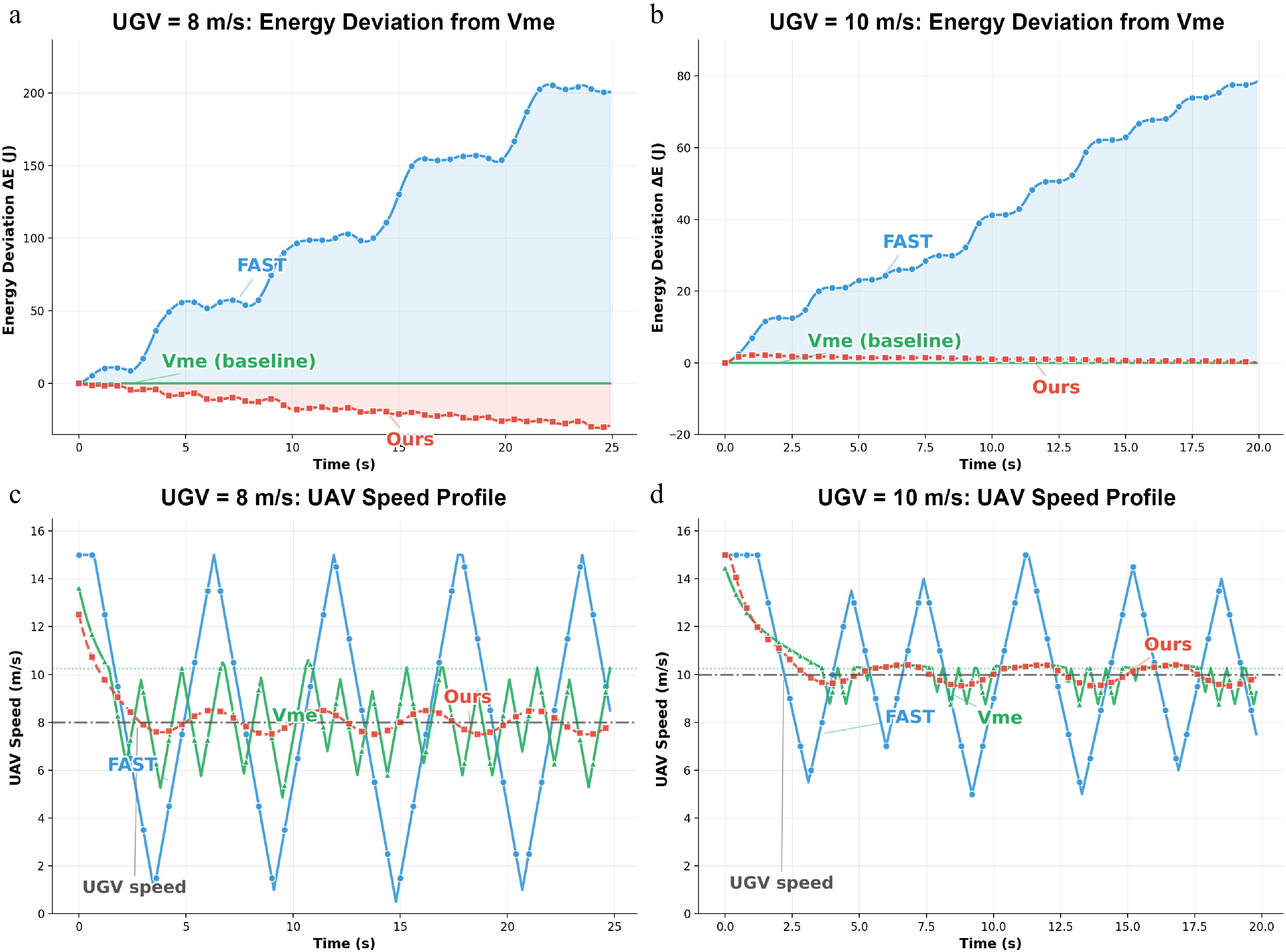
Figure 3.
Constraint-inactive comparison relative to Vme. (a), (b) Cumulative energy deviation $ \Delta E(t) $ from the Vme baseline for $ v_g\in\{8,10\}\,\mathrm{m/s} $ over the full episode. (c), (d) Corresponding UAV speed profiles under the same setting.
As shown in Fig. 3a and b, for
$ v_g=8\;\mathrm{m/s} $ $ v_{\max} $ $ v_g=10\;\mathrm{m/s} $ These results illustrate the energy–time trade-off induced by different speed-selection strategies. FAST represents a time-prioritized strategy, whereas Vme represents an energy-per-distance cruise strategy. The proposed method avoids unnecessary high-speed oscillations while maintaining task progress, reflecting a tunable compromise between operational speed and energy efficiency.
Propulsion energy model ablation
-
This experiment ablates the propulsion-energy term in the learning objective and isolates its effect under the safety-filtered execution pipeline. At each time step, the policy outputs a nominal velocity command, which is then passed through the Shield to produce an executed velocity
$ {\bf{v}}_{{\rm{safe}},t} $ $ w_E>0 $ $ w_E=0 $ Table 1. Key parameters for the propulsion-energy ablation study.
Symbol Meaning Value $ \Delta t $ Sampling period $ 0.1 {\rm{s}} $ T Episode horizon 5,000 steps $ L\times W $ Workspace size in $ xy $ 200 m × 180 m $ v_{\max} $ UAV speed limit 15 m/s $ [z_{\min},z_{\max}] $ UAV altitude bounds [5, 30] m $ z_0 $ Initial UAV altitude 15 m $ d_{{\rm{ahead}}} $ Look-ahead reference distance 30 m $ s_{\min} $ Minimum ahead distance 4 m $ \varepsilon_{{\rm{LOS}}} $ LOS margin threshold 1.0 m S LOS samples on the segment 64 τ Soft-min temperature 0.25 $ (d_{{\rm{safe}}},d_{{\rm{crit}}},p) $ LOS risk mapping parameters (1.0 m, 0.2 m, 2) $ m_{{\rm{col}}} $ Collision margin 0.3 m The only difference between EnergyConstrained and Unconstrained is the energy weight $ w_E $ (EnergyConstrained: $ w_E>0 $, Unconstrained: $ w_E=0 $). For evaluation, propulsion power is computed from
$ {\bf{v}}_{{\rm{safe}},t} $ $ \eta_E = \dfrac{ E_{{\rm{Unconstrained}}} - E_{{\rm{EnergyConstrained}}} }{ E_{{\rm{Unconstrained}}} } \times 100{\text{%}}. $ (45) To reduce bias from different completion times, cumulative energy is aligned by UAV trajectory arc length:
$ s_0 = 0,\qquad s_k = \sum\limits_{i=0}^{k-1}\left\|{\bf{x}}_u^{i+1}-{\bf{x}}_u^{i}\right\|. $ (46) Scenario 1 starts from an initial NLOS condition and requires LOS recovery while navigating the corridor. The planar trajectories are shown in Fig. 4. As shown in Fig. 4, both methods complete the traversal, while EnergyConstrained follows a feasible route with less aggressive local deviations. The corresponding altitude evolution and LOS clearance are presented in Fig. 5.
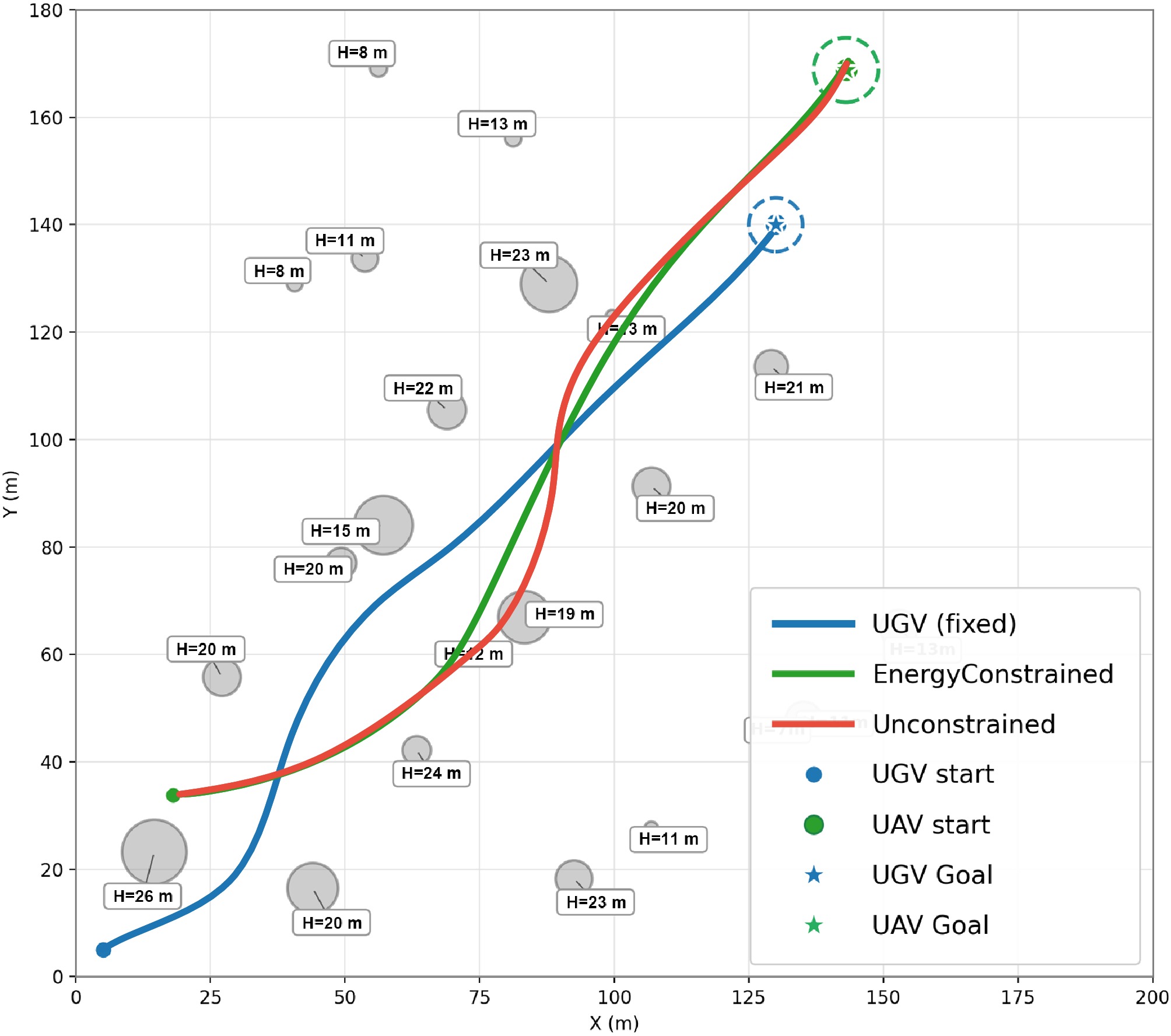
Figure 4.
Scenario 1 (initial NLOS): planar trajectories of the UGV and UAV.
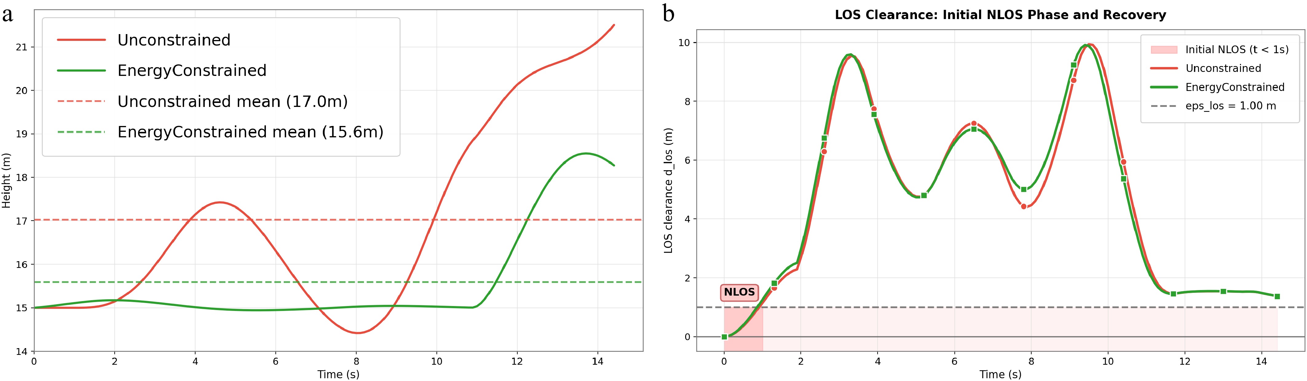
Figure 5.
Scenario 1 (initial NLOS): altitude evolution and LOS clearance for Unconstrained and EnergyConstrained. (a) UAV height profiles. (b) LOS clearance/margin metric.
Figure 5 shows that EnergyConstrained maintains a lower mean altitude while recovering LOS clearance above
$ \varepsilon_{\rm{LOS}}=1.0\rm{\ m} $ 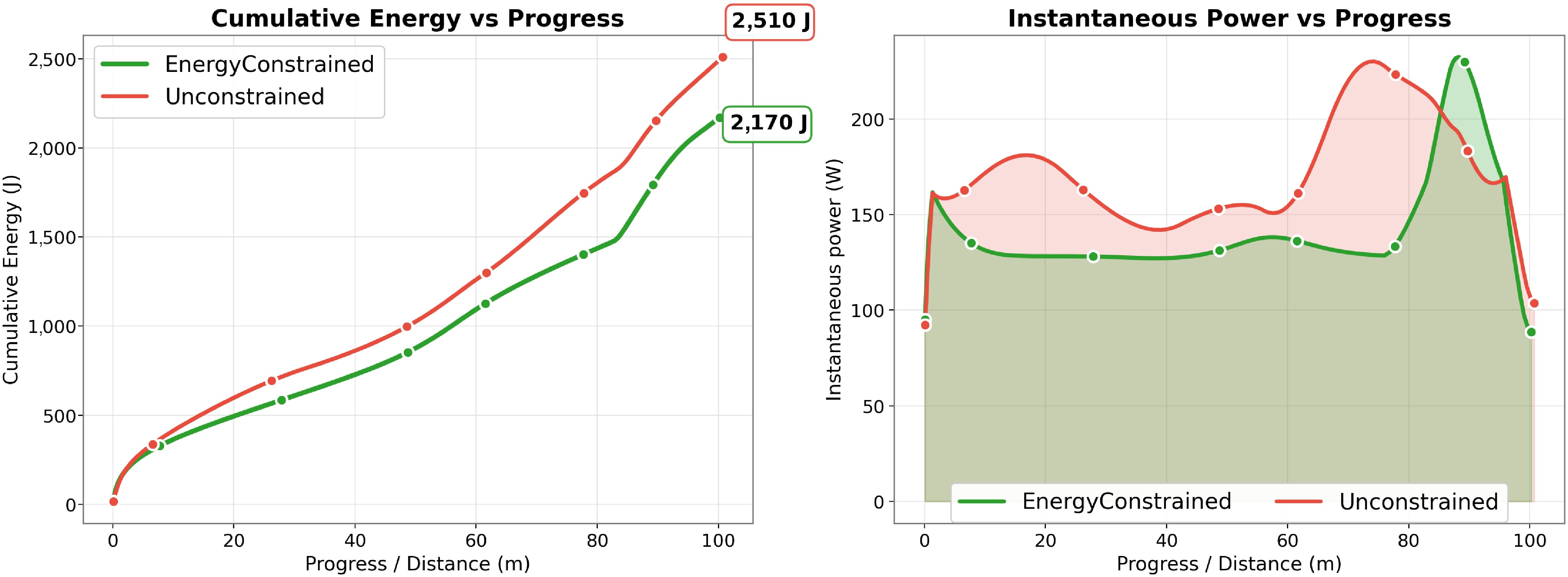
Figure 6.
Scenario 1 (initial NLOS): cumulative propulsion energy aligned by progress and instantaneous power computed from executed velocities using Eq. (40).
As shown in Fig. 6, at the same progress, EnergyConstrained reduces cumulative energy from
$ 2,510\rm{\ J} $ $ 2,170\ \rm{J} $ $ \eta_E=13.5{\text{%}} $ Scenario 2 starts from an initial LOS condition in a more cluttered environment. The planar trajectories are shown in Fig. 7.
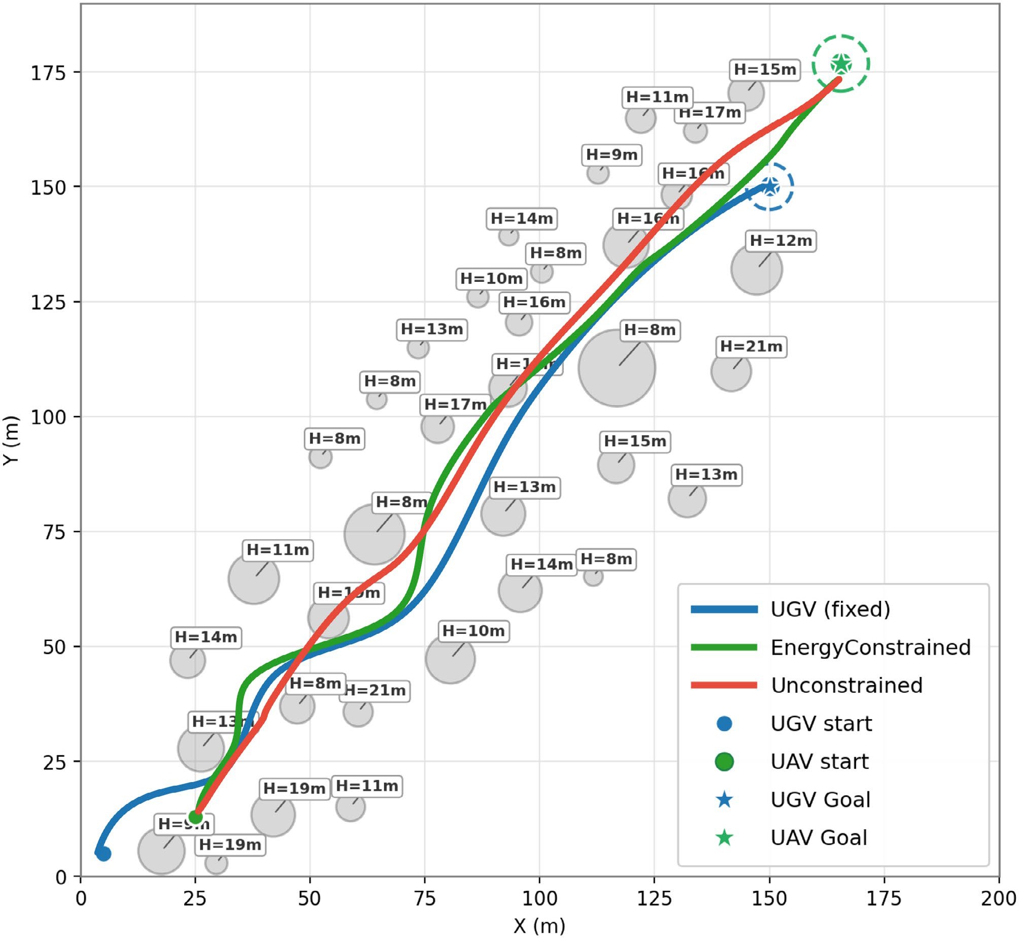
Figure 7.
Scenario 2 (initial LOS): planar trajectories of the UGV and UAV in a cluttered urban environment with multiple obstacles.
Figure 7 shows that both methods reach the goal through similar corridors, while EnergyConstrained yields smoother local adjustments and avoids unnecessary lateral detours in the cluttered region. The altitude and LOS profiles are shown in Fig. 8, further illustrating the corresponding vertical-motion behavior and connectivity-maintenance performance.
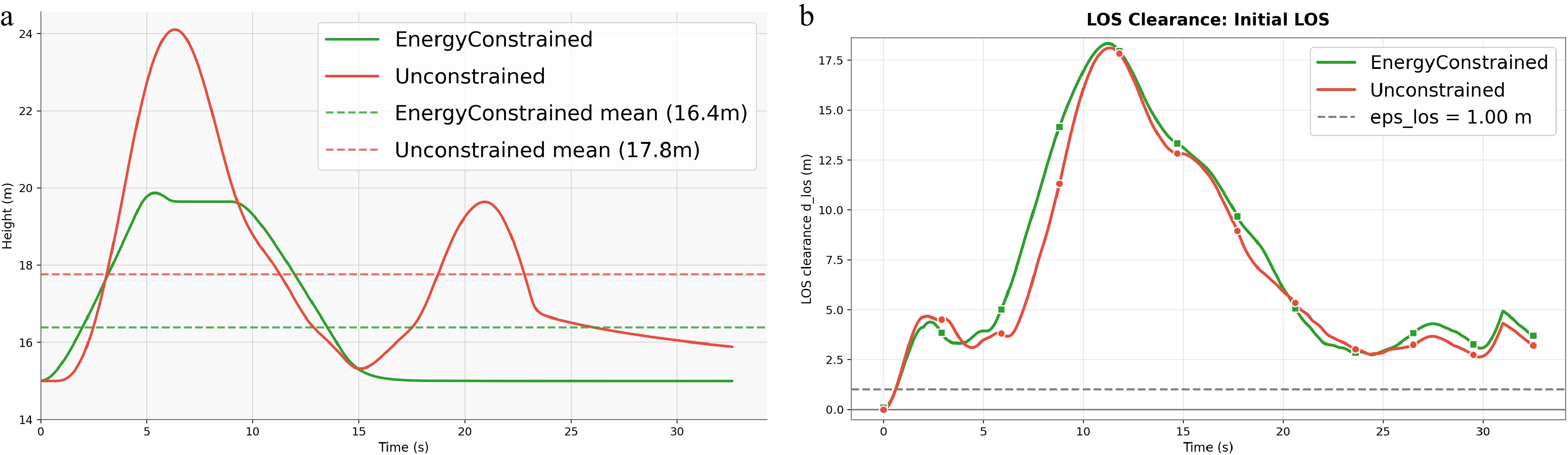
Figure 8.
Scenario 2 (initial LOS): altitude evolution and LOS clearance for Unconstrained and EnergyConstrained. (a) UAV height profiles. (b) LOS clearance/margin metric.
Figure 8 further shows that EnergyConstrained maintains a lower mean altitude while keeping the LOS clearance above the required margin. The progress-aligned energy and instantaneous power are shown in Fig. 9.
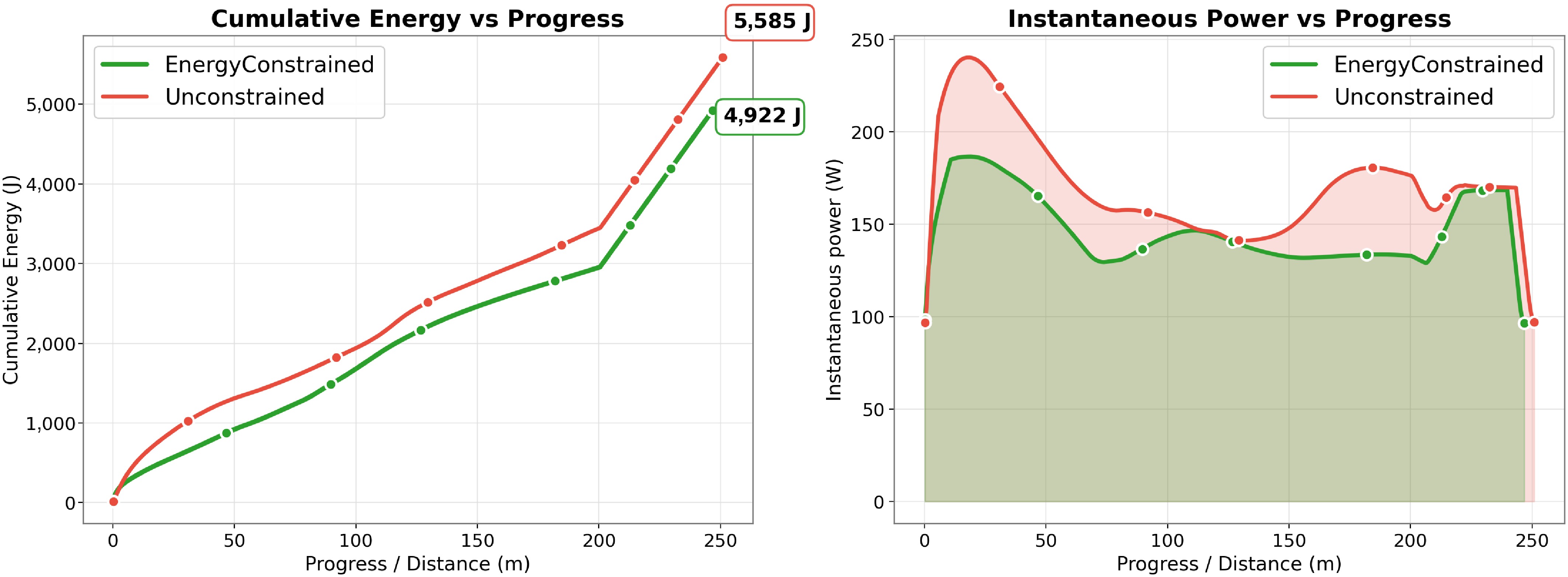
Figure 9.
Scenario 2 (initial LOS): cumulative propulsion energy aligned by progress and instantaneous power computed from executed velocities using Eq. (40).
As shown in Fig. 9, EnergyConstrained reduces cumulative energy from
$ 5,585\rm{\ J} $ $ 4,922\ \rm{J} $ $ \eta_E=11.9{\text{%}} $ For an illustrative battery-budget interpretation, the propulsion-energy reduction can be mapped to a surrogate-based relative endurance proxy under the same usable-battery and reserve-energy assumptions. Let
$ E_{bat}^{use} $ $ E_{res} $ $ \bar{P} $ $ \hat T_{{\rm{op}}} = \dfrac{E_{{\rm{bat}}}^{{\rm{use}}}-E_{{\rm{res}}}}{\bar P}. $ (47) For a progress-aligned mission segment, the relative endurance gain induced by an energy-saving ratio
$ \eta_E $ $ G_T = \dfrac{\hat T_{{\rm{EnergyConstrained}}}} {\hat T_{{\rm{Unconstrained}}}} -1 \approx \dfrac{1}{1-\eta_E/100}-1 . $ (48) Under these idealized battery-budget assumptions, the energy reductions of 13.5% and 11.9% correspond to surrogate-based relative endurance proxies of approximately 15.6% and 13.5%, respectively. This calculation is not a prediction of real flight duration or battery discharge, which would require platform-specific battery, payload, and power-system measurements.
Disturbance-aware dynamic validation
-
To examine whether the energy-saving trend is sensitive to idealized kinematic execution, we further conduct a disturbance-aware dynamic validation. This experiment does not replace real flight tests or high-fidelity hardware-in-the-loop validation, but tests whether the proposed energy-aware shielded execution remains beneficial when command delay, velocity-response lag, and wind disturbance are introduced during evaluation.
At each time step, the Shield first produces the feasible command
$ {\bf{v}}_{{\rm{safe}},t} $ $ {\bf{v}}_{{\rm{del}},t} = \begin{cases} {\bf{v}}_{{\rm{safe}},t-d}, & t\ge d,\\ {\bf{v}}_{{\rm{safe}},0}, & t \lt d, \end{cases} $ (49) where, d is the command delay measured in control steps. The delayed command is then passed through a first-order velocity-response model:
$ {\bf{v}}_{{\rm{act}},t} = \begin{cases} {\bf{v}}_{{\rm{del}},t}, & \tau_{{\rm{v}}}=\infty,\\ {\bf{v}}_{{\rm{act}},t-1} + \alpha_{{\rm{v}}} \left( {\bf{v}}_{{\rm{del}},t} - {\bf{v}}_{{\rm{act}},t-1} \right), & 0 \lt \tau_{{\rm{v}}} \lt \infty, \end{cases} $ (50) where,
$ \tau_{{\rm{v}}} $ $ \alpha_{{\rm{v}}} = \min\left(\dfrac{\Delta t}{\tau_{{\rm{v}}}},\,1\right). $ (51) The initial actual velocity
$ {\bf{v}}_{{\rm{act}},0} $ A horizontal wind disturbance
$ {\bf{v}}_{{\rm{wind}},t} $ $ {\bf{x}}_{u,t+1} = {\bf{x}}_{u,t} + \left( {\bf{v}}_{{\rm{act}},t} + {\bf{v}}_{{\rm{wind}},t} \right)\Delta t . $ (52) The UGV still follows the reference update in Eq. (17). For energy evaluation, propulsion power is recomputed from the wind-relative airspeed:
$ {\bf{v}}_{{\rm{air}},t} = {\bf{v}}_{{\rm{act}},t} - {\bf{v}}_{{\rm{wind}},t}. $ (53) The disturbed step-wise propulsion energy is computed as
$ E_{{\rm{dist}},t} = \max\left( P_{{\rm{hor}}} \left(\left\|P_{xy}{\bf{v}}_{{\rm{air}},t}\right\|_2\right) + P_z \left({\bf{e}}_z^\top{\bf{v}}_{{\rm{air}},t}\right), 0 \right)\Delta t . $ (54) Three execution cases are considered. The Ideal case uses
$ d=0 $ $ \tau_{{\rm{v}}}=\infty $ $ d=1 $ $ \tau_{{\rm{v}}}=0.3\,{\rm{s}} $ $ 2.8\,\mathrm{m/s} $ $ d=2 $ $ \tau_{{\rm{v}}}=0.2\,{\rm{s}} $ $ 5.7\,\mathrm{m/s} $ 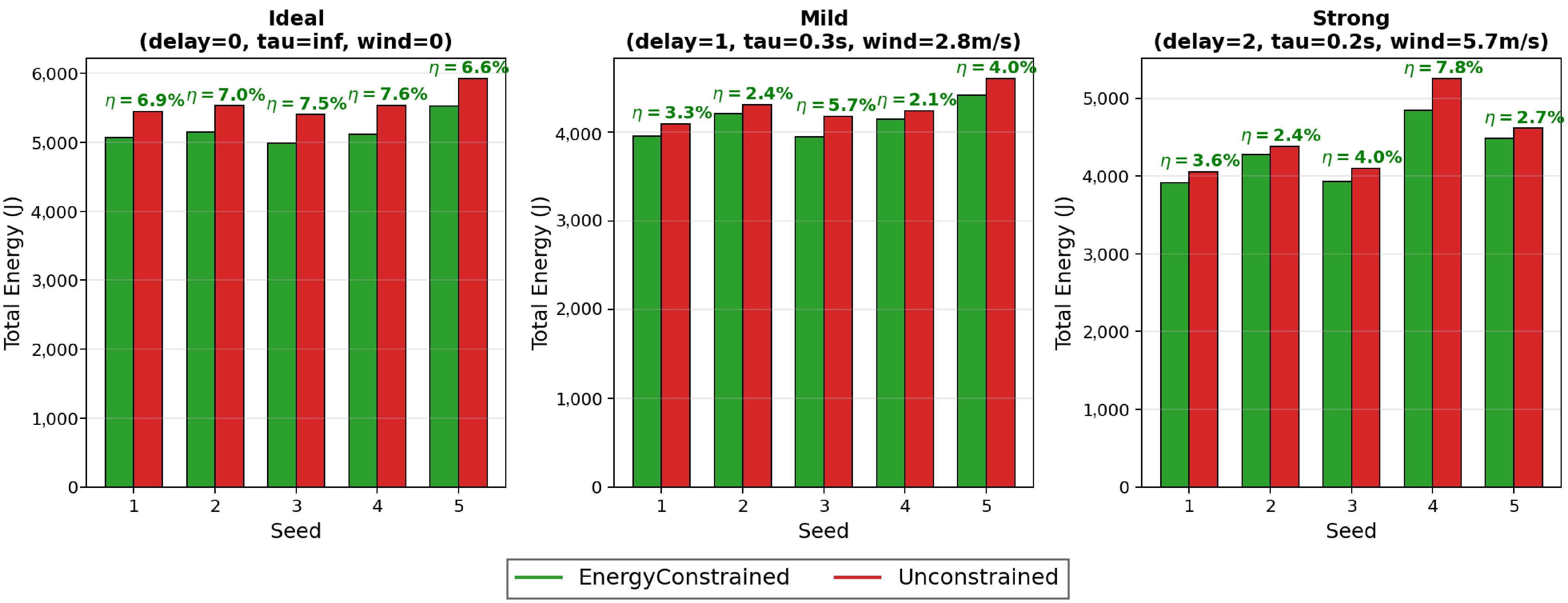
Figure 10.
Energy comparison under ideal, mild-disturbance, and strong-disturbance execution. A positive $ \eta_E $ indicates that EnergyConstrained consumes less total propulsion energy than Unconstrained under the same disturbance case.
As shown in Fig. 10, EnergyConstrained consistently consumes less propulsion energy than Unconstrained in all three execution cases. The average energy-saving ratios are 7.13%, 3.51%, and 4.11% under Ideal, Mild, and Strong execution, respectively. Although the saving ratio decreases after introducing delay, velocity-response lag, and wind disturbance, the energy-saving trend remains positive. The corresponding LOS safety statistics are shown in Fig. 11.
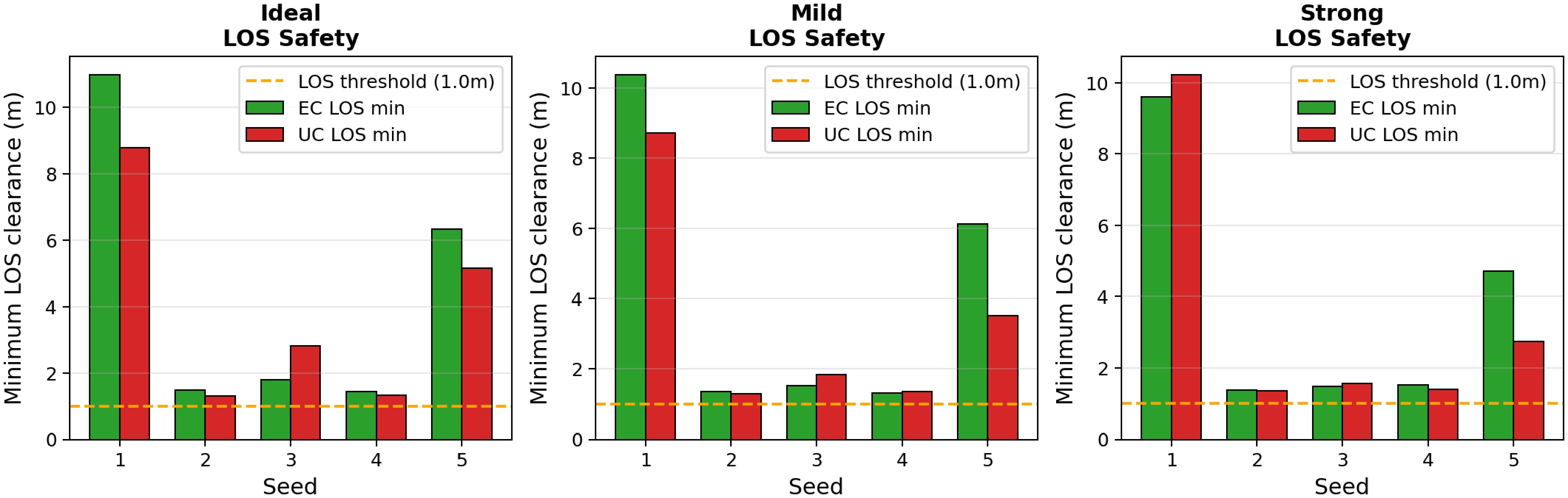
Figure 11.
Minimum LOS clearance under ideal, mild-disturbance, and strong-disturbance execution. The dashed line denotes the LOS safety threshold of 1.0 m.
Figure 11 shows that both methods maintain LOS safety, with the minimum LOS clearance remaining above the
$ 1.0\,{\rm{m}} $ Propulsion energy model comparison
-
This experiment compares three embedded propulsion-energy models under identical task settings and constraint-consistent execution. We evaluate our model, denoted as Proposed, against two representative baselines. The task specification, obstacle field, UGV reference trajectory, motion limits, and feasibility checks are identical across methods. At each step, the controller produces a nominal UAV velocity command
$ {\bf{v}}_{{\rm{des}},t} $ $ {\bf{v}}_{{\rm{safe}},t} $ $ {\bf{v}}_{{\rm{safe}},t} $ Let
$ {\bf{v}}_{{\rm{safe}},t}=[{\bf{v}}_{xy,t}; v_{z,t}] $ $ V_t=\|{\bf{v}}_{xy,t}\|_2 $ $ \begin{align} P_1(V) &= P_0\left(1+\dfrac{3V^2}{U_{{\rm{tip}}}^2}\right), \end{align} $ (55) $ \begin{align} P_2(V) &= P_i\left(\sqrt{1+\dfrac{V^4}{4v_0^4}}-\dfrac{V^2}{2v_0^2}\right)^{\dfrac{1}{2}}, \end{align} $ (56) $ \begin{align} P_3(V) &= \dfrac{1}{2}d_0\rho sA\,V^3, \end{align} $ (57) $ \begin{align} P_{{\rm{hor}},t} &= P_1(V_t) + \kappa_t P_2(V_t) + P_3(V_t). \end{align} $ (58) The vertical power and total step-wise energy are:
$ P_{z,t} = k_{{\rm{climb}}}\max(v_{z,t},0) + k_{{\rm{desc}}}\max(-v_{z,t},0), $ (59) $ P_{{\rm{tot}},t} = P_{{\rm{hor}},t}+P_{z,t}, \qquad E_t = \max(P_{{\rm{tot}},t},0)\Delta t, \qquad E_{{\rm{ep}}} = \sum\limits_{t=0}^{T-1}E_t . $ (60) All physical parameters are shared across models. The only difference is the definition of
$ \kappa_t $ The Proposed model uses:
$ \kappa_{{\rm{Prop}},t}=1. $ (61) Gao et al.[34] increase
$ \kappa_t $ $ {\bf{a}}_{xy,t} = \dfrac{{\bf{v}}_{xy,t}-{\bf{v}}_{xy,t-1}}{\Delta t}, \qquad \kappa_{{\rm{Gao}},t} = 1+\left(\dfrac{\|{\bf{a}}_{xy,t}\|_2}{g}\right)^2 . $ (62) Yang et al.[35] further couple acceleration and speed through an equivalent drag term:
$ V_t=\|{\bf{v}}_{xy,t}\|_2,\quad A_t=\|{\bf{a}}_{xy,t}\|_2,\quad ({\bf{a}} \cdot {\bf{v}})_t = ({\bf{a}}_{xy,t})^{\top}{\bf{v}}_{xy,t}, $ (63) $ { \kappa_{{\rm{Yang}},t} = 1+ \dfrac{ 4m^2A_t^2+\rho^2A_{{\rm{eq}}}^2V_t^4 +4m\rho A_{{\rm{eq}}}({\bf{a}} \cdot {\bf{v}})_tV_t^2 } {4(mg)^2}, } $ (64) where, m is the vehicle mass, g is the gravitational acceleration, and
$ A_{{\rm{eq}}} $ To reduce bias from different completion distances, cumulative energy is aligned by UAV trajectory arc length:
$ s_0=0,\qquad s_k=\sum\limits_{i=0}^{k-1}\left\|{\bf{x}}_u^{i+1}-{\bf{x}}_u^{i}\right\|_2 . $ (65) We also report energy per distance
$ E_{{\rm{ep}}}/D $ 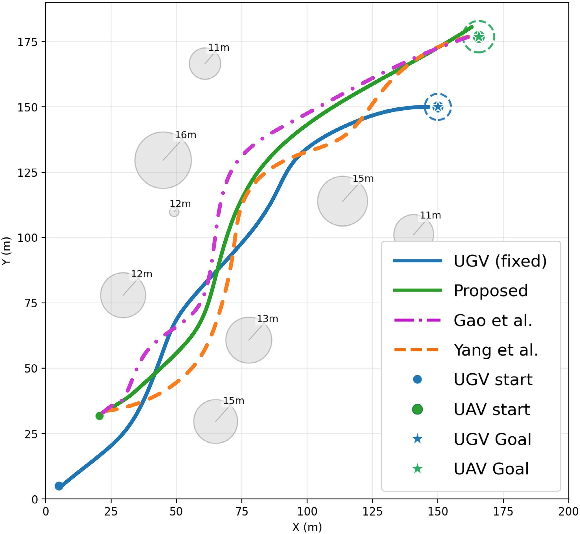
The kinematic traces in Fig. 12 are consistent with the energy outcomes. All methods complete obstacle avoidance and forward tracking, while Proposed follows a more compact route and travels the shortest distance. The progress-aligned cumulative energy and instantaneous power are shown in Fig. 13.
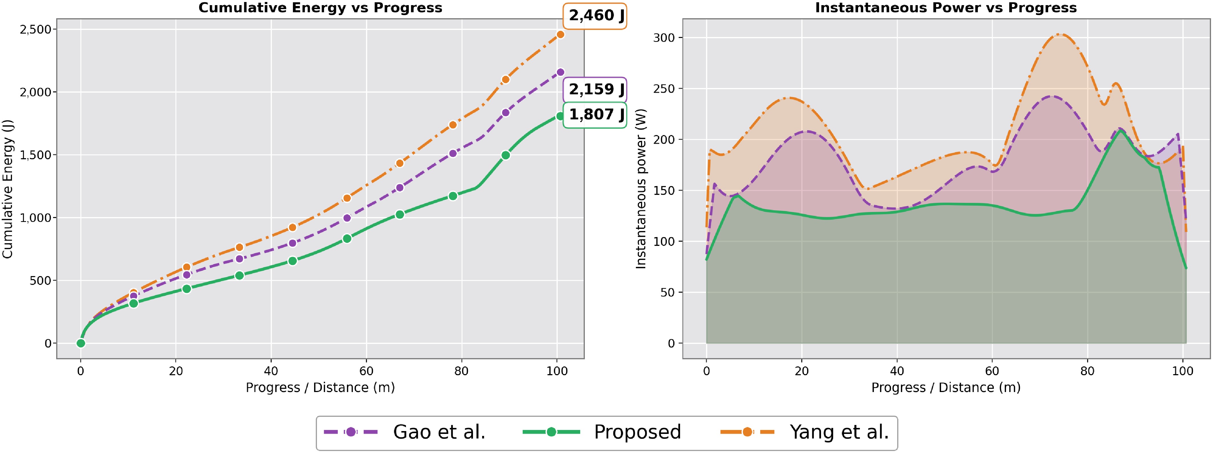
Figure 13.
Progress-aligned cumulative energy and instantaneous power. Cumulative energy is compared at matched UAV progress to reduce bias from different travel distances.
Figure 13 shows that Proposed has the lowest progress-aligned cumulative energy and fewer high-power peaks. The LOS margin comparison is shown in Fig. 14.
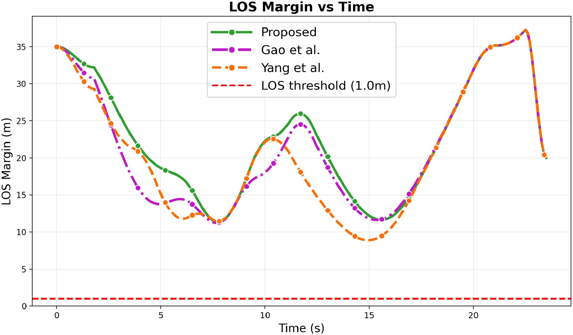
Figure 14.
LOS margin over time under the three embedded propulsion-energy models, with $ \varepsilon_{\rm{LOS}}=1.0\rm{\ m} $.
Figure 14 shows that all three methods keep the LOS margin above
$ \varepsilon_{{\rm{LOS}}}=1.0\,{\rm{m}} $ 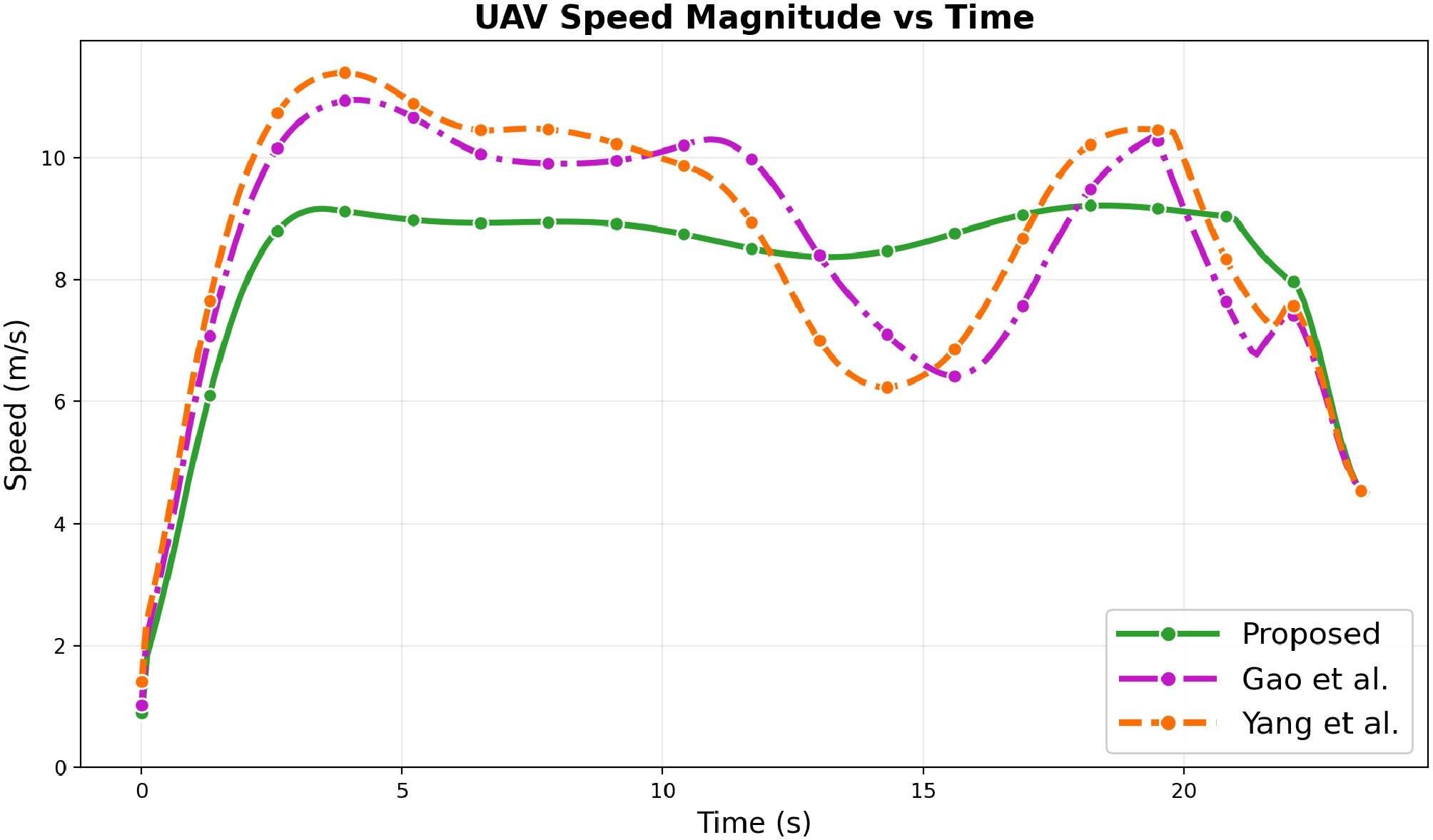
Figure 15.
UAV speed magnitude over time under the three embedded propulsion-energy models.
Figure 15 further shows that Proposed maintains a lower and smoother speed profile, reducing operation in the high-speed region where the parasitic term
$ P_3(V)\propto V^3 $ Table 2. Comparison of three embedded propulsion-energy models under identical task settings and feasibility enforcement.
As reported in Table 2, Proposed reduces total energy by 16.3% and 26.5% compared with Gao et al. and Yang et al., respectively.
Overall, this comparison indicates that the proposed SAC–Shield design remains energy-efficient under different embedded propulsion-energy formulations, although absolute energy values may change with a higher-fidelity vehicle-calibrated power model.
Online runtime evaluation
-
To examine practical online performance, we profile the execution stage after training. The sampling period is
$ \Delta t=0.1 $ $ N=15 $ $ S=64 $ Table 3. Online timing breakdown of the proposed SAC–Shield controller under $ N=15 $, $ S=64 $, and 2,000 control steps.
Component Mean (ms) Std. (ms) 95th Perc. (ms) LOS evaluation 11.59 1.86 15.16 ESDF field query 0.17 0.05 0.23 Field-gradient query 0.16 0.04 0.21 Candidate-direction search 11.69 1.95 15.33 Shield mapping 9.99 5.04 15.71 Total per-step time 33.60 7.56 46.76 As reported in Table 3, the complete online control loop requires
$ 33.60\pm7.56 $ $ 29.8 $ $ 46.76 $ $ 100 $ $ O(KNS) $ $ 100 $ Table 4. Scalability of online feasibility evaluation with respect to local obstacles N and LOS samples S.
Setting N S Mean time (ms) Frequency (Hz) Small 5 16 2.75 363.69 Moderate 10 64 17.00 58.82 Default-scale 15 64 22.02 45.41 Large 20 128 58.53 17.08 Largest tested 30 128 86.53 11.56 -
The proposed framework provides an online motion-level correction mechanism for perceived geometric changes. At each control step, the Shield reconstructs the admissible velocity set using the latest UAV–UGV states, obstacle information, and LOS geometry. Thus, newly detected obstacles or updated LOS conditions can affect the executed command at the next control step.
The current study focuses on geometric feasibility and motion-level propulsion-energy evaluation. Network congestion, packet loss, bandwidth variation, dynamic-obstacle prediction, and detailed communication-network effects are not explicitly modeled. Therefore, the reported robustness should be interpreted as motion-level and visibility-level robustness rather than full communication-network robustness.
Moreover, the propulsion-energy metric used in this work is based on an executed-velocity-driven surrogate model. Physical flight tests, actual onboard power or battery-discharge measurements, high-fidelity hardware-in-the-loop validation, nonlinear battery dynamics, state-of-charge estimation, and high-fidelity motor-propeller modeling are outside the scope of the present work. Accordingly, the reported energy reductions should be interpreted as simulation-based motion-level estimates rather than calibrated real-world battery-saving measurements.
For long-duration deployment, the online energy estimate could be connected to a supervisory battery-management layer in future work. The remaining usable energy can be monitored by
$ E_{{\rm{rem}},t}=E_{{\rm{bat}}}^{{\rm{use}}}-\sum_{\ell=0}^{t}E_{\ell} $ $ E_{{\rm{bat}}}^{{\rm{use}}} $ $ E_{{\rm{rem}},t} $ -
This paper proposes an energy-efficient and constraint-consistent UAV–UGV control framework for forward reconnaissance under LOS maintenance constraints. A SAC policy generates nominal velocity commands, and the Shield maps them to feasible executed velocities. The executed velocity is used consistently for state propagation, energy accounting, reward evaluation, and feasibility checking.
Simulation results based on the adopted motion-level propulsion-energy surrogate show that the proposed method reduces estimated UAV propulsion energy while supporting sampled LOS feasibility and obstacle-avoidance feasibility in the tested scenarios. The inactive-constraint experiment verifies that the energy reduction mainly comes from learned speed scheduling rather than excessive Shield intervention. The propulsion-energy ablation confirms the benefit of including energy cost in the learning objective. The disturbance-aware validation shows that the estimated energy-saving trend remains positive under command delay, velocity-response lag, and wind disturbance in simulation. The propulsion-model comparison and runtime evaluation further indicate that the proposed SAC–Shield design retains a lower estimated propulsion-energy trend under different embedded energy formulations and is computationally tractable for online execution.
Future work will extend the framework to multi-UAV relay selection, multi-UGV task allocation, physical flight tests with actual onboard power measurements, high-fidelity hardware-in-the-loop validation, nonlinear battery dynamics and state-of-charge estimation, high-fidelity motor-propeller modeling, and fleet-level energy-aware coordination.
-
The authors confirm their contributions to the paper as follows: study conception and design, methodology: Wen X, Hou B; software and data curation, draft manuscript preparation: Wen X; validation and analysis: Wen X, Chen Y, Wang D, Fan Z; manuscript review and editing: Hou B, Chen Y, Wang D, Fan Z; supervision: Hou B, Fan Z; project administration and funding acquisition: Hou B. All authors reviewed the results and approved the final version of the manuscript.
-
The datasets generated during and/or analyzed in the current study are available from the corresponding author on reasonable request.
-
The authors declare no conflict of interest.
- Copyright: © 2026 by the author(s). Published by Maximum Academic Press, Fayetteville, GA. This article is an open access article distributed under Creative Commons Attribution License (CC BY 4.0), visit https://creativecommons.org/licenses/by/4.0/.
-
About this article
Cite this article
Wen X, Hou B, Chen Y, Wang D, Fan Z. 2026. Energy-efficient UAV−UGV coordinated control under line-of-sight maintenance constraint. International Journal of Micro Air Vehicles 18: e014 doi: 10.48130/mav-0026-0016 

Energy-efficient UAV−UGV coordinated control under line-of-sight maintenance constraint
- Received: 13 April 2026
- Revised: 29 June 2026
- Accepted: 04 August 2026
- Published online: 17 September 2026
Abstract: Cooperative operations in which a UAV advances ahead of a UGV to conduct forward reconnaissance often require maintaining a Line-of-Sight (LOS) link for reliable data transmission, yet cluttered urban environments can intermittently block this link and degrade coordination. UAV onboard energy is typically the limiting resource, and recovering link visibility under occlusion can induce detours, altitude changes, and frequent speed regulation that increase propulsion energy consumption and reduce operating time. To address this challenge, this paper proposes a UAV motion control framework that minimizes energy consumption while maintaining LOS and avoiding obstacles. A rotary-wing propulsion energy model is used for energy quantification, and a soft actor-critic (SAC) reinforcement learning policy generates nominal velocity commands. These commands are processed through an online safety filter (Shield) to map nominal velocity to executed velocity, ensuring compliance with constraints while maximizing energy efficiency. Additionally, a real-time LOS evaluation metric is introduced to assess occlusion risk and provide online guidance for feasibility enforcement. Simulation results demonstrate that the proposed method effectively maintains stable LOS and avoids collisions in complex environments, significantly reducing UAV energy consumption and improving trajectory smoothness.