










-
The flying fish is a type of marine fish possessing a unique trans-media locomotion capability spanning both water and air[1]. After leaping out of the water at high speed, it can spread its broad pectoral fins and glide in the air for tens or even hundreds of meters. This mode of locomotion not only demonstrates the subtlety of biological evolution but also provides a natural biomimetic paradigm for the development of high-performance foldable-wing aircraft. The pectoral fins of the flying fish can be folded and retracted against the sides of the body underwater to reduce drag, and then rapidly deployed in the air to form a lifting surface, thereby achieving the unified design goals of 'large wing area when deployed' and 'small envelope when stowed'. This offers important inspiration for the structural design of foldable wings.
Inspired by the unique locomotion of flying fish, researchers worldwide have conducted extensive studies on biomimetic flying fish robots. In 1921, Clayton[2] observed that when a flying fish leaps out of the water, its caudal fin beats laterally while the pectoral fins vibrate at a very high frequency, and found that the structural characteristics of the pectoral fin—stiff leading edge and flexible trailing edge—are key to thrust generation. Fish[3] of West Chester University performed morphometric analysis on flying fish specimens and found that the wing loading and aspect ratio of flying fish are closer to those of birds and bats, and their gliding flight exhibits characteristics of high speed and low sinking rate. Davenport[4] of Millport University, Ireland, systematically described the flight process of flying fish: the flying fish approaches the water surface at a speed of approximately 10 m/s, exits the water at an angle of about 30°, achieves gliding speeds of 15–20 m/s, and covers a single gliding distance of approximately 50 m.
In terms of aerodynamic characteristics research, Park & Choi[5] of Seoul National University conducted wind tunnel tests. The results showed that the maximum lift coefficient of the flying fish is approximately 0.78, occurring within the angle of attack range of 30° to 35°, and the maximum lift-to-drag ratio is approximately 4.37, occurring within the angle of attack range of −5° to 0°. The deployment of the pelvic fins significantly increased lift and lift-to-drag ratio, and enhanced longitudinal static stability. The jet-like accelerated flow structure formed between the pectoral and pelvic fins is the main reason for the lift enhancement. Deng et al.[6] from Zhejiang University employed computational fluid dynamics methods and obtained a maximum lift coefficient of 1.03 (at 35°) and a maximum lift-to-drag ratio of 4.7 (at 6°). Saro-Cortes et al.[7] from Princeton University, based on a biomimetic flying fish robotic model, investigated the effects of pelvic fin geometric parameters on aerodynamic performance through wind tunnel tests. The results indicated that the aerodynamic efficiency is highest when the pelvic fins are positioned directly behind the pectoral fins.
In terms of biomimetic flying fish robot design, Gao & Techet[8] of the Massachusetts Institute of Technology proposed four conceptual designs based on electromagnetic actuation. Their study found that the drag required to be overcome by a flying fish swimming underwater at a speed of 10 m/s is approximately 23 N, corresponding to a power density as high as 2,810 W/kg. Desbiens et al.[9] from Stanford University designed a jump-gliding robot that uses catapult-assisted takeoff and achieves a maximum gliding distance of 5 m. Lu[10] from Zhejiang University developed a biomimetic flying fish robotic prototype capable of pectoral fin retraction and deployment, posterior body deflection, and high-frequency caudal fin flapping, achieving autonomous swimming with a maximum speed of 0.3 m/s. Huo[11] established a force analysis model for robot swimming based on the locomotion characteristics of flying fish, and subsequently designed and fabricated a biomimetic flying fish robot prototype capable of surface swimming, reaching a maximum speed of 0.9 m/s (1.63 BL/s). Qi[12] designed a biomimetic robotic fish capable of pectoral fin retraction and deployment as well as caudal fin oscillation, and established a kinematic model of the robotic fish based on Lighthill's slender body theory. Pham et al.[13] developed a biomimetic robotic fish named KUFish, capable of fast underwater swimming and leaping out of the water. In experiments, KUFish swam 0.68 m within 0.68 s and leapt out of the water at a speed of 1.35 m/s, with a Froude number close to 1, demonstrating the ability to completely exit the water. Zhong[14] proposed a mechatronic system design method for a water-air cross-medium biomimetic flying fish robot, achieving retraction, deployment, and rotation of both pectoral fins, with a maximum speed of 1.12 m/s. Chen[15] completed the prototype design of a biomimetic flying fish robot, achieving a maximum speed of 2.54 m/s (4.93 BL/s).
In summary, researchers worldwide have conducted extensive studies on biomimetic flying fish robots and achieved significant progress. In terms of research on the biological prototype and aerodynamic characteristics of the flying fish, the physiological structure and locomotion mechanisms have been clarified, providing a biological foundation for biomimetic design[2–7]. Regarding the design of biomimetic flying fish robots, technologies such as high-frequency caudal fin oscillation and pectoral fin folding and deployment have been developed, enabling continuous improvement in underwater swimming speed as well as brief water-leaping or gliding capabilities[8–15].
However, existing research has mostly focused on the physiological characteristics of the flying fish itself and the aerodynamic characteristics during the gliding phase in air, while engineering efforts have centered on underwater swimming. Only a few researchers have achieved brief water exit or gliding, and studies on biomimetic flying fish with foldable wings that truly emphasize aerial flight capability remain relatively scarce. More importantly, existing research lacks depth in addressing two key issues: the biomimetic pectoral fin folding mechanism and the close-coupled pectoral-pelvic fin configuration, resulting in low bionic fidelity of current achievements. Therefore, conducting research on biomimetic flying fish foldable-wing aircraft and thoroughly exploring the design of the pectoral-fin-inspired folding mechanism, the aerodynamic characteristics of the close-coupled pectoral-pelvic fin configuration, and flight performance is of significant theoretical importance and application value for advancing research on biomimetic flying fish robots.
The development of biomimetic flying fish foldable-wing aircraft faces two major challenges:
First, in the close-coupled pectoral-pelvic fin configuration of the flying fish, the distance between the pectoral fins (analogous to wings) and the pelvic fins (analogous to horizontal tail surfaces) is extremely small. This results in a short tail trimming moment arm for the biomimetic aircraft, and the tail is significantly affected by the downwash from the wings. Consequently, there is a need to develop an airfoil that balances high lift with low moment characteristics.
Second, membrane-frame wings have a small thickness and are prone to flow separation. The connection between the rigid leading-edge structure and the membrane wing surface requires a delicate aerodynamic fairing. Moreover, although the supporting rib skeleton can better achieve a biomimetic curved surface configuration, its structural complexity imposes higher demands on mechanism design and manufacturing processes.
To address the above issues, this study takes the flying fish as a biomimetic prototype and carries out the development of a prototype of a flying fish-inspired aircraft with foldable pectoral fins and pelvic fins in a close-coupled configuration. In terms of overall design, the aircraft layout and dimensions are determined based on the morphological characteristics of the flying fish. A dihedral angle is incorporated into the wings to enhance lateral stability, while an anhedral angle is designed for the tail to achieve positive roll–yaw coupling. The tail layout also draws inspiration from the aerodynamic characteristics of the close-coupled pectoral-pelvic fin configuration of the flying fish. For aerodynamic design, based on thin airfoil theory combined with a genetic algorithm and interpolation optimization, a membrane airfoil that meets the lift and moment requirements is obtained, and the leading-edge transition region is faired and refined. In structural design, inspired by the radial skeleton structure of the flying fish pectoral fin, a foldable supporting rib configuration is constructed using distributed rotating shafts and carbon-fiber composite materials. Kevlar fibers are employed to enhance the strength of structural connections, and a four-bar linkage mechanism is used to achieve wing folding and deployment. For experimental validation, through conventional configuration validation flight tests, biomimetic configuration wind tunnel tests, and biomimetic configuration validation flight tests, the performance of the developed membrane-frame foldable wing structure, the actuation performance of the folding mechanism, and the aerodynamic and handling stability characteristics of the principal prototype are systematically verified, all of which fully meet the design expectations. The research presented in this paper aims to provide a theoretical basis and technical support for the further development of high-performance biomimetic flying fish foldable-wing aircraft.
-
After leaping out of the water, the flying fish in nature quickly adjusts its posture and enters a gliding mode, during which its pectoral fins, pelvic fins, and caudal fin cooperate to form a stable aerodynamic configuration[16,17]. In their review, Davenport[4] pointed out that during gliding flight, the deployed pectoral fins serve as the main lifting surface, the caudal fin is elevated and remains stationary, while the pelvic fins play an important role in maintaining gliding attitude stability. Early observers such as Clayton[2] also noted that the leading edge of the flying fish pectoral fin is stiff, whereas the trailing edge is flexible.
This study adopts the real flying fish as the biomimetic object and accordingly determines the overall layout of the aircraft, as shown in Fig. 1. Designed to mimic the pectoral fin of the flying fish, the wing adopts a foldable configuration that balances a large wing area in the deployed state with a compact envelope in the stowed state. The tail, mimicking the abdominal fins, adopts an anhedral configuration. The rationale for this layout is that the flexible wing makes it difficult to install conventional ailerons; the anhedral tail achieves a positive roll–yaw coupling effect, thereby allowing the tail control surfaces to be designed as elevons that function as both elevators and ailerons. The vertical tail serves only as a stabilizing surface to simplify the structure and ensure directional stability[18−21].
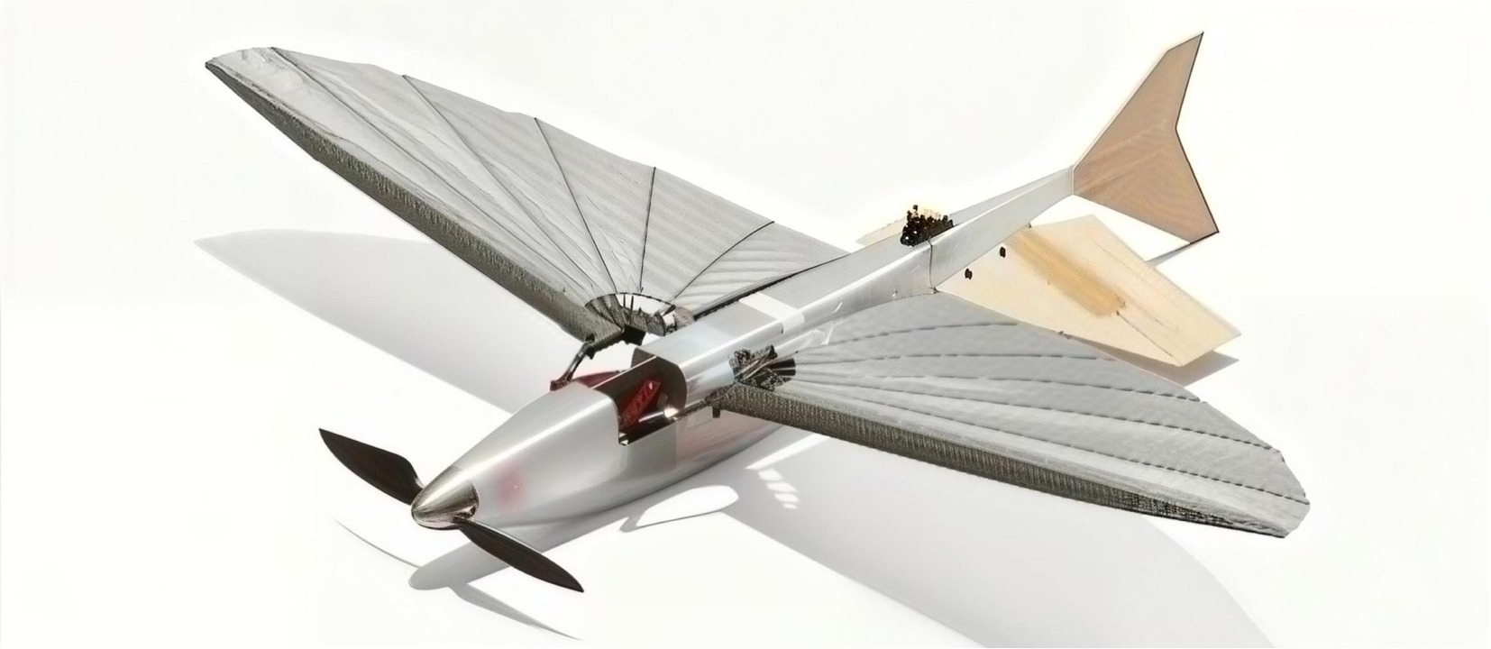
Figure 1.
Digital visualization of the proposed aircraft design.
The body length of real flying fish exhibits considerable interspecific variation. Studies have shown that adult flying fish typically range in length from 150 to 500 mm[4], with the length of a single pectoral fin being approximately two-thirds of the body length[22]. In their numerical simulation study of flying fish flight trajectories, Deng et al.[6] used a flying fish model with a body length of 250 mm, which falls within the typical range of real flying fish, and obtained gliding distance results that agreed well with biological observational data.
Taking factors such as bionic fidelity into careful consideration, this study sets the overall aircraft length to 450 mm and the wingspan to 623 mm. This size lies near the upper limit of the typical body length range of flying fish, which facilitates the accommodation of more power and electronic equipment while ensuring a sufficiently large wing area and providing a reasonable lift margin for subsequent aerodynamic design.
The wind tunnel test results of the biomimetic flying fish robot model by Saro-Cortes et al.[7] from Princeton University indicate that the aerodynamic efficiency of the flying fish is highest when the pelvic fins are positioned directly behind the pectoral fins, and that a larger pitch angle of the pelvic fins leads to higher aerodynamic efficiency. During flight, the flying fish must strike a trade-off between aerodynamic efficiency and longitudinal stability to achieve the optimal pectoral-pelvic fin configuration.
Based on this, the present study innovatively applies a highly biomimetic close-coupled pectoral-pelvic fin configuration, positioning the tail surfaces directly behind the wing and close to the trailing edge. As shown in Fig. 2 for comparison, the specific layout is strictly designed according to the physiological structure and morphology of the real flying fish, in order to achieve optimal bionic fidelity and aerodynamic efficiency.
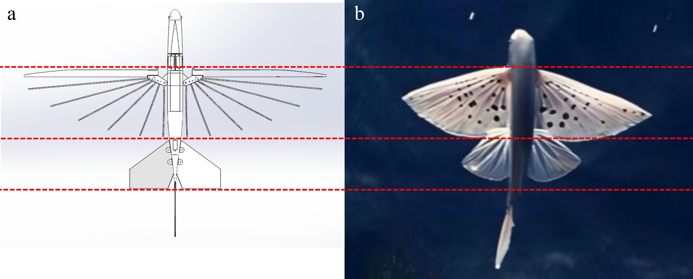
Figure 2.
Layout comparison: (a) the layout design; (b) the real flying fish.
The position of the center of gravity is shown in Fig. 3. The coordinates of the complete aircraft’s center of gravity are (0.000, 11.607, −140.460), which is roughly located at the 25% chord position and meets the static stability design requirements for low-speed aircraft. The weights of each aircraft component and onboard equipment are listed in Table 1.
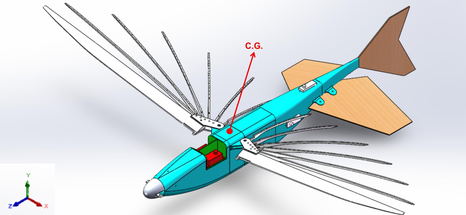
Figure 3.
Weight and CG of the aircraft.
Table 1. Component weights of the aircraft.
Component or equipment Weight Fuselage 52.14 g Wings 43.82 g Horizontal tail 5.54 g Vertical tail 2.77 g Propeller cowling 8.73 g Motor 10 g Electronic speed controller 15 g Battery 33 g Receiver 3 g Servos 34 g The key parameters are shown in Table 2.
Table 2. Key parameters of the aircraft.
Parameter Value Length 450 mm Wingspan 623 mm Fuselage length 350 mm Internal volume 350 mL Frontal area 1,650 mm2 (55 mm × 30 mm) CLmax 1.146 (L/D)max 5.589 Maximum gross weight 270 g Vmax 30 m/s Aerodynamic design
Wing configuration design
-
The wing shape is designed in imitation of the real flying fish. Morphometric measurements of flying fish specimens by Fish[3] indicate that the pectoral fin area and wingspan increase as power functions of body mass, and that wing loading exhibits a positive allometric relationship with body mass, with the range of wing loading being comparable to that of birds and bats. The study further points out that flying fish can be classified into two aerodynamic layouts based on wing surface distribution: the 'single-wing type' and the 'double-wing type'. The former, exemplified by the genus Exocoetus, uses elongated pectoral fins as the primary lifting surface to pursue higher flight speeds; the latter, exemplified by the genus Cypselurus, relies on both pectoral fins and pelvic fins to provide lift, aiming for better lift characteristics.
This study adopts a relatively large wing area to provide a certain lift margin. A dihedral angle of 8° is designed for the wing, primarily based on the following two considerations:
First, there are no control surfaces on the wing, so the coupling effect between roll and yaw needs to be enhanced through the configuration itself.
Second, the dihedral angle helps to improve the lateral static stability of the aircraft, which is particularly important for flexible-wing aircraft.
Basic wing configuration is shown in Fig. 4.
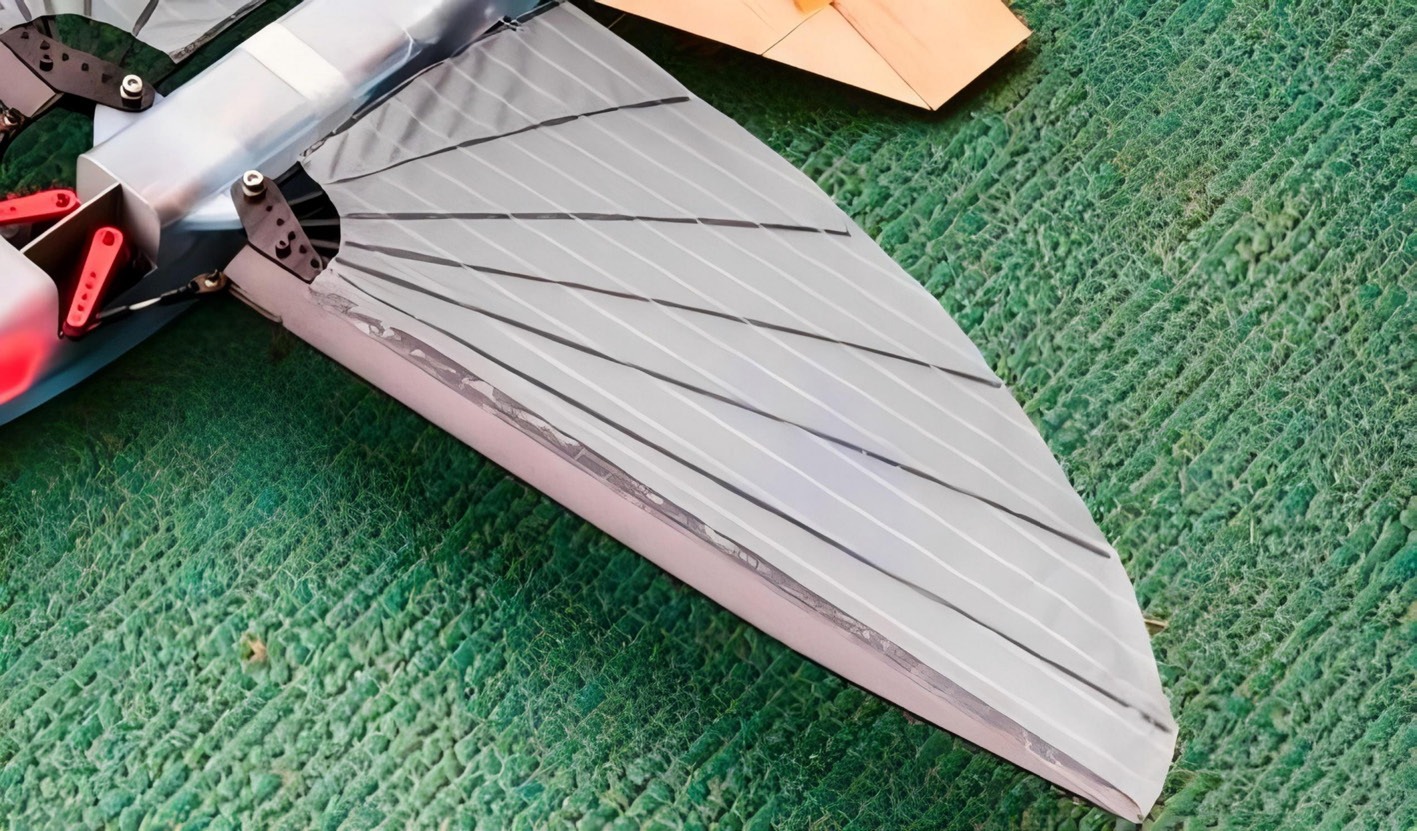
Figure 4.
Wing configuration.
Airfoil optimization design
-
The pectoral fins of real flying fish have extremely small thickness, and directly adopting their geometric characteristics would pose difficulties for engineering implementation. To address this issue, this study carries out airfoil design based on Prandtl's lifting-line theory and thin airfoil theory. Theoretical analysis indicates that when the airfoil thickness is extremely small, its aerodynamic characteristics are primarily influenced by the shape of the camber line. Deng et al.[6] employed numerical simulation methods to investigate three different flying fish models, obtaining a maximum lift coefficient of 1.03 and a maximum lift-to-drag ratio of 4.7, and found that the aerodynamic performance of flying fish is comparable to that of low-Reynolds-number flying animals such as eagles and petrels. Based on this, a base airfoil with a relatively small thickness is selected, and optimization is performed using a genetic algorithm combined with interpolation fusion to obtain a thin airfoil that meets the design requirements. The final membrane airfoil is then obtained by extracting its camber line.
The aerodynamic design of the airfoil faces another challenge: the close-coupled pectoral-pelvic fin configuration, which mimics the real flying fish, results in a short distance between the tail and the wing, leading to a short tail moment arm and significant influence from wing downwash. This necessitates an airfoil that possesses both high lift and low moment characteristics. To address this issue, this study selects the 'albatross' GOE 174 airfoil as the base high-lift airfoil and the MH 114 airfoil as the base low-moment airfoil. Four rounds of genetic algorithm optimization are carried out, focusing on the lift characteristics and relative thickness of the GOE 174 airfoil[23], yielding an airfoil with a high lift coefficient and small relative thickness. However, this airfoil exhibits poor moment coefficient characteristics, and its direct application would deteriorate the longitudinal stability of the aircraft. Therefore, the MH 114 airfoil is introduced and fused with this airfoil through interpolation, ultimately obtaining a dedicated thin airfoil that balances lift and moment requirements. The application of this airfoil effectively avoids the design compromise of excessively increasing the inverted V-tail area to compensate for moment. A comparison of the relevant airfoils is shown in Fig. 5.
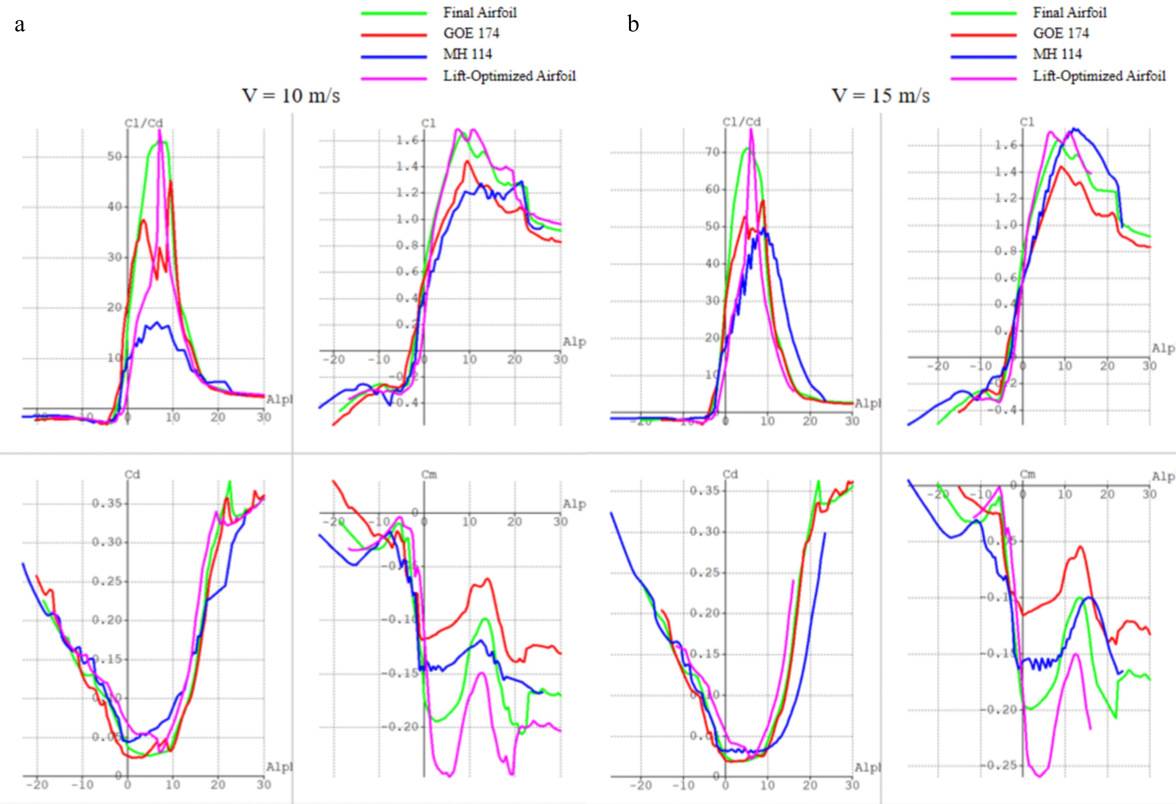
Figure 5.
Comparison of relevant airfoils: (a) V = 10 m/s; (b) V = 15 m/s.
The details of the four-stage genetic optimization algorithm are as follows: the objective function for each stage is to maximize CL. The constraints are that the maximum relative thickness shall not exceed that of the initial airfoil, and the pitching moment coefficient at 0 angle of attack shall not exceed −0.3. In the first stage, the initial population size is set to 100, the elite population size is 40, the crossover probability is 0.9, and the mutation probability is 0.05, so as to search for high-quality populations within a wide range. Starting from the second stage, the initial population size, elite population size, crossover probability, and mutation probability are all reduced to 50% of those of the previous stage, which improves search precision, reduces the probability of losing optimal solutions, and lowers computational complexity.
Wing structure design
Leading edge design
-
Biological studies have shown that the leading edge of the pectoral fin of the real flying fish possesses high structural stiffness, providing effective support to the wing surface. To address the inherent shortcomings of membrane wings—small thickness and susceptibility to flow separation—and to ensure structural stiffness while achieving higher aerodynamic efficiency, this study designs a leading-edge reinforcement structure inspired by the flying fish. Since the thickness of the leading edge is much greater than that of the membrane airfoil, the leading edge is generated by taking equidistant points above and below the camber line to ensure a smooth transition of the overall camber line of the airfoil. However, the geometric step between the rear part of the leading edge and the membrane inevitably has an adverse effect on the attached flow on the lower surface. To remedy this, a dedicated fairing modification is applied to the lower part of the leading edge, thereby improving the local flow condition. Details of the leading edge are shown in Fig. 6.
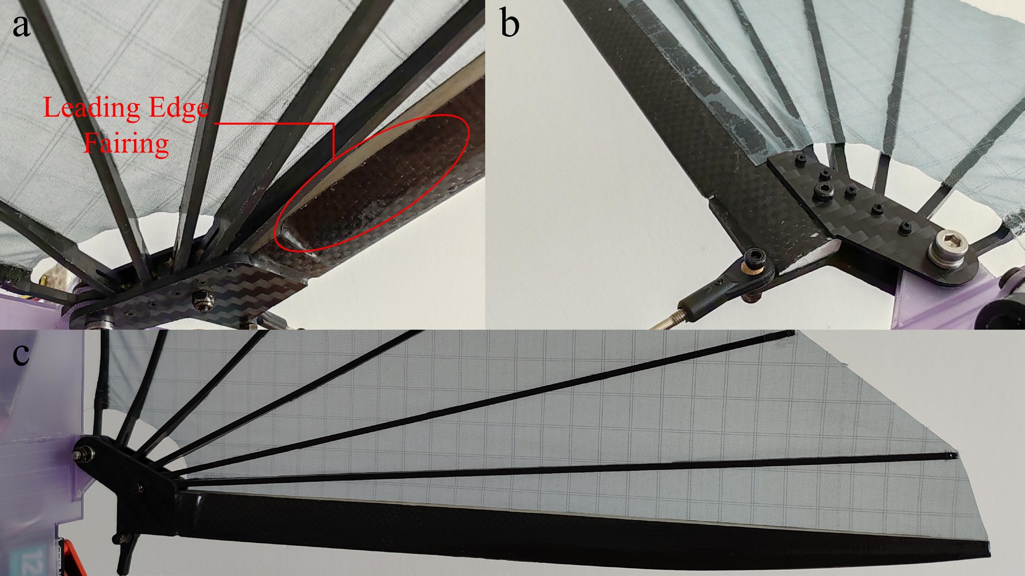
Figure 6.
The leading edge: (a) lower surface; (b) upper surface; (c) overall view.
To verify that the leading-edge fairing design can ensure the stability of the flow field on the lower surface, computational fluid dynamics (CFD) is employed in this study to simulate the flow field on the lower surface of the leading edge, with the simulation results presented in Fig. 7. The simulation is conducted under the following conditions: freestream velocity of 15 m/s, angle of attack of 0°, and fluid density of 1.225 kg/m3; the mesh consists of 1,287,415 cells; the total boundary layer thickness is 0.01 m, with 28 layers and a growth rate of 1.15; the turbulence model is the K-Omega SST. The simulation results indicate that the fairing design achieves favorable smoothness and stability of the flow field on the lower surface.
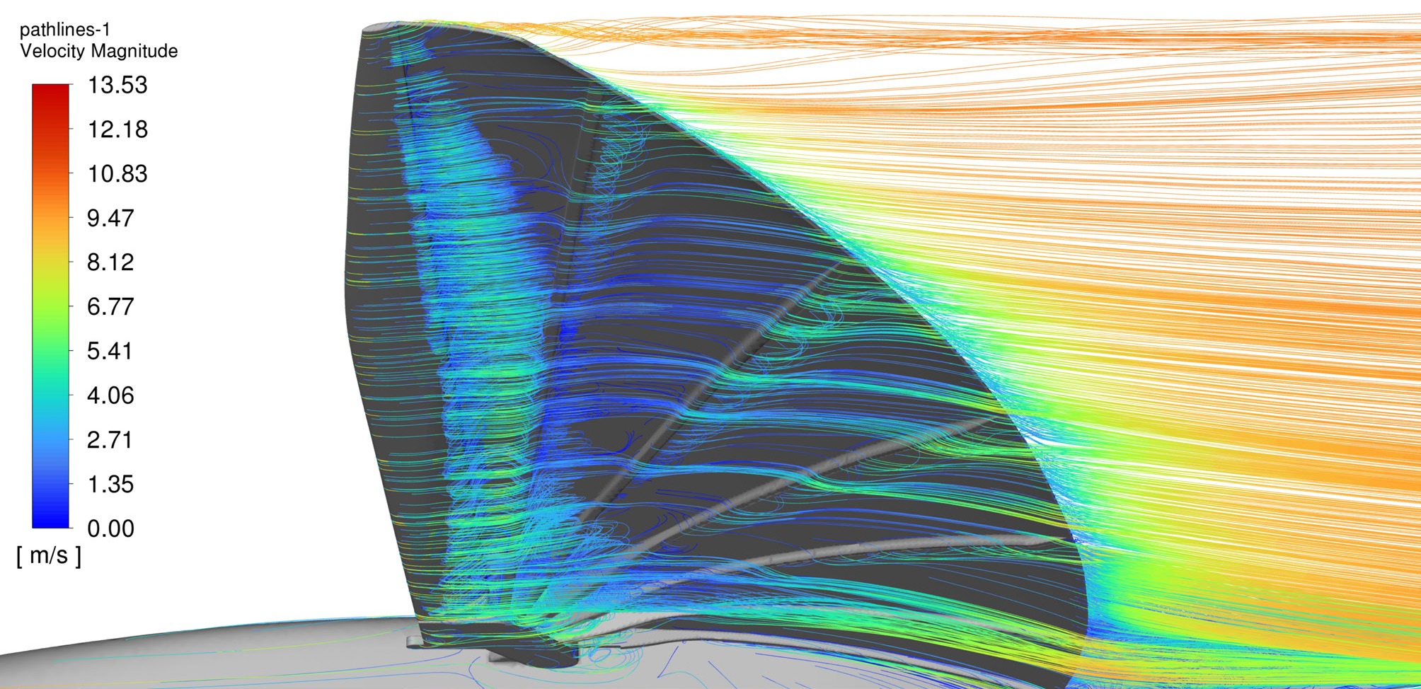
Figure 7.
Flow field visualization of the lower leading edge.
Design of the membrane-frame foldable wing
-
The structural design of the foldable wing takes the real flying fish pectoral fin skeleton as its biomimetic prototype. Qi[12] found in her study that the flying fish pectoral fin is composed of fin rays and a fin membrane; the hardness of the fin rays gradually decreases from the base to the tip, and the fin membrane is smooth and elastic, covering the upper surface of the fin rays to form a fan-like structure with a smooth upper surface and rib-like protrusions on the lower surface. Based on an in-depth investigation of the actuation mechanism of the flying fish pectoral fin, Li[24] discovered that the vein distribution of the pectoral fin is radial, with the primary veins being rigid and the secondary veins flexible. Meanwhile, Gao[22] from Jilin University reported that the upward bulging of the membrane at the trailing edge of the flying fish pectoral fin alters the pressure distribution on the wing surface and has an optimizing effect on lift characteristics. Her two-way fluid-structure interaction simulations further revealed that the flexible fin membrane undergoes passive deformation under incoming flow; the pressure difference between the upper and lower surfaces causes the membrane to bulge, creating a 'curvature effect' that generates greater lift than a rigid model.
Drawing on the above research findings, this study appropriately simplifies the pectoral fin skeleton of the flying fish, retaining only the primary branching structure, so as to maintain biomimetic characteristics while ensuring engineering feasibility. The supporting rib skeleton is arranged radially about a collinear distributed shaft configuration. The supporting rib skeleton and collinear distributed shaft structure are shown in Fig. 8. Compared with the coaxial skeleton scheme, which, although structurally simple, struggles to support the curved surface of a cambered membrane wing and suffers from high drag and low efficiency, the distributed shaft layout allows each supporting rib to rotate independently. This not only effectively supports the preset curved shape of the wing membrane but also provides some suppression of membrane buffeting[25−27].
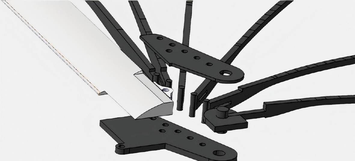
Figure 8.
Supporting rib skeleton and collinear distributed shaft structure.
The upper surfaces of the supporting ribs are bonded to the non-elastic membrane, and together they maintain the precise shape of the upper surface of the wing. Each movable supporting rib consists of a rotating shaft and a carbon-fiber sheet. Kevlar fibers pass through the lightening holes on the supporting ribs and are wrapped around the shafts, forming an enhanced structural connection. The fixed supporting ribs near the fuselage side do not participate in the folding motion and are therefore kept parallel to the outer surface of the fuselage by means of limiting plates.
The wing shape strictly follows the geometric characteristics of the real flying fish. To effectively suppress membrane buffeting, except for the longest supporting rib, which is positioned relatively close to the leading edge to provide primary support, the remaining supporting ribs are arranged approximately equidistantly in the trailing-edge region. Moreover, the membrane deforms under aerodynamic loads during flight, and the radially arranged supporting rib skeleton allows the trailing edge of the membrane to undergo a deformation similar to the upward bulging of the membrane at the trailing edge of the flying fish pectoral fin. This enhances wing lift while ensuring that the wing surface deformation remains within an acceptable range. The overall structure achieves the design goals of small volume, high strength, and high efficiency. The constraints applied by the fixing plates on the skeleton regulate the direction of the folding and deployment motion, avoiding structural interference during movement. Ultimately, the two seemingly contradictory design objectives—'large wing area when deployed' and 'small envelope when stowed'—are achieved, and high lift characteristics are obtained through biomimetic means.
Fuselage design
-
To reduce flight drag, a smooth connection design is adopted between the nose and the spinner, ensuring an overall streamlined shape. The fuselage contour minimizes frontal area and form drag as much as possible while satisfying the internal equipment layout requirements. Based on the caudal fin dimensions of the real flying fish and the needs of the internal power and electronic equipment, the fuselage length is set to 350 mm, the internal volume is approximately 350 mL, and the frontal area is 55 mm × 30 mm. Details of the fuselage are shown in Fig. 9.
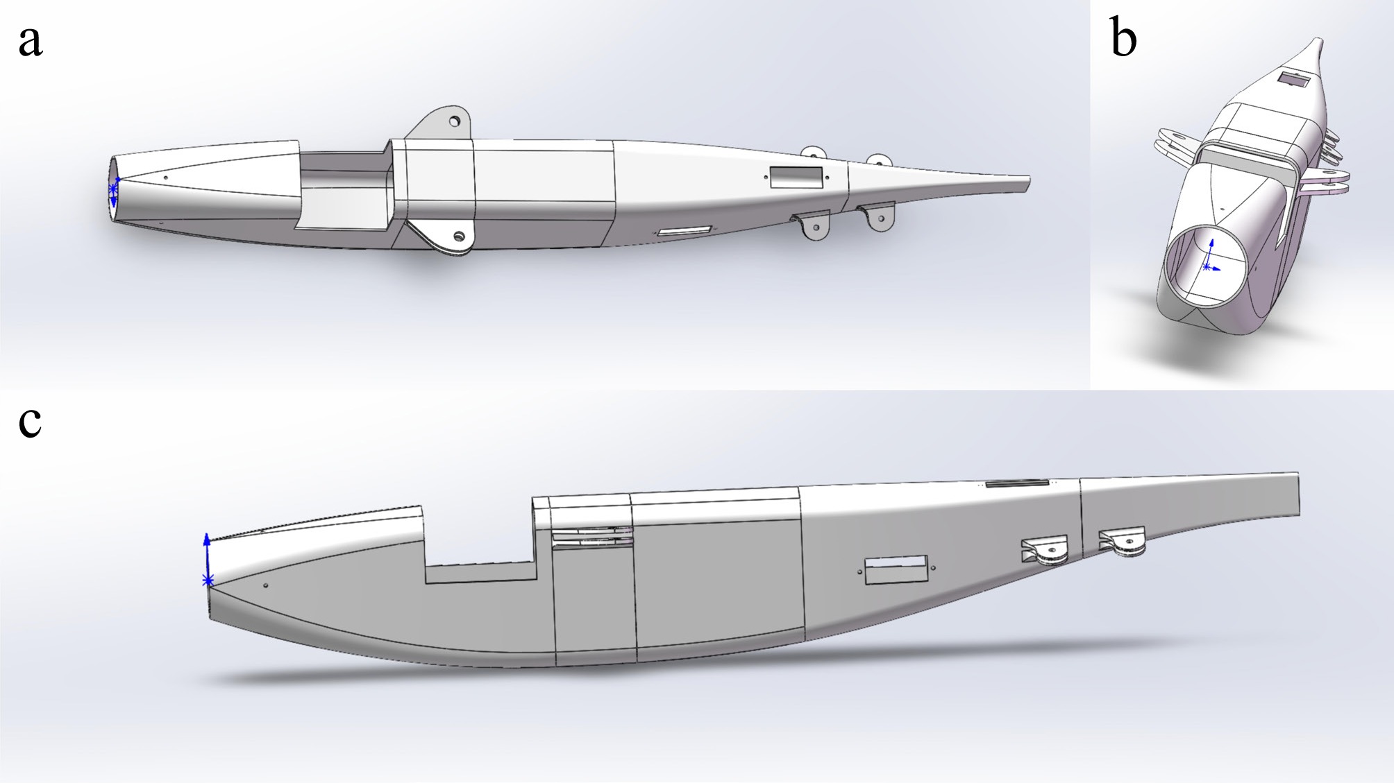
Figure 9.
3D model of the fuselage: (a) top view; (b) front view; (c) side view.
Folding mechanism design
-
The folding and deployment of the foldable wing are realized through a four-bar linkage mechanism[28]. A connecting rod links the wing leading edge and the servo arm, with spherical hinges employed at the joints to accommodate angular variations during motion. When the servo arm rotates, it drives the wing leading edge to rotate about the connecting shaft on the fuselage via the connecting rod. The individual supporting ribs are then sequentially folded or deployed to their predetermined positions under the tension provided by the membrane. The detailed design of the four-bar linkage mechanism is shown in Fig. 10.
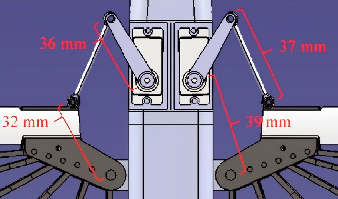
Figure 10.
Four-bar folding mechanism.
In the design, the fuselage segment length is d = 39 mm, the servo arm length is a = 36 mm, and the leading-edge segment length is c = 32 mm. To ensure complete folding and deployment of the foldable wing, the rotation angle of the leading-edge segment is set to ψ = 90°. Based on this, the connecting rod length b and the driving link rotation angle φ are to be determined.
According to the displacement constraint equation of the four-bar linkage mechanism, the closed-loop equation of the mechanism can be obtained from the geometric constraint condition of constant connecting rod length as follows:
$ {(d + c\cos{\psi - a\cos{\varphi)}}}^{2} + {(c\sin{\psi - a\sin{\varphi)}}}^{2} = b^{2} $ (1) When the leading-edge segment is at the initial position ψ1 = 0°, substituting φ1 = 0° yields the connecting rod length:
$ b = (d + c) - a = 35\ {\rm{mm}} $ (2) When the leading-edge segment rotates to ψ2 = 90°, substituting d = 39 mm, a = 36 mm, c = 32 mm, and b = 35 mm into the constraint equation and simplifying using the trigonometric identity cos2φ + sin2φ = 1 yields:
$ 2808\cos\varphi+2304\sin\varphi=2616 $ (3) Finally, the servo arm rotation angle is obtained as φ
$ \approx\ $ To compensate for manufacturing clearances and motion errors, improve the reliability of the mechanism, and guarantee smooth folding and deployment of the wing under any condition, the connecting rod length is set to 37 mm in the actual design. According to Grashof's theorem, the sum of the shortest link length and the longest link length (32 + 39 = 71 mm) is less than or equal to the sum of the other two link lengths (36 + 37 = 73 mm); therefore, the mechanism forms a crank-rocker mechanism[29]. The servo arm rotates by approximately 80°, and the connecting rod drives the wing leading edge to rotate by 90°. The remaining supporting ribs are then sequentially folded or deployed under the tension of the membrane, thereby achieving the folding and deployment of the wing skeleton in imitation of the pectoral fin of the flying fish.
The folding mechanism and foldable wing structure have undergone a total of 43 ground deployment/retraction tests, 19 test flights, and 27 aerial deployment–retraction cycles. The folding mechanism operates smoothly during deployment and retraction. No engineering-detectable damage is observed on the foldable wing structure, which can sustain repeated flight loads normally. The above results fully verify the reliability and durability of the folding mechanism and folded wing assembly.
Power system, electronic equipment, and manufacturing process
-
This project employs a brushless motor with a maximum power of 240 W and a 20 A electronic speed controller, paired with a 150 mm two-blade folding propeller. A two-cell lithium polymer battery is used, providing a maximum airborne cruise endurance of 10 min. The aircraft is equipped with a miniaturized express long range system (ELRS) receiver. Two 12 g waterproof servos are arranged to control the folding and deployment of the left and right folding wing mechanisms, respectively, and two 5 g waterproof servos are used to control the differential tail surfaces. The power system and electronic equipment are shown in Fig. 11.
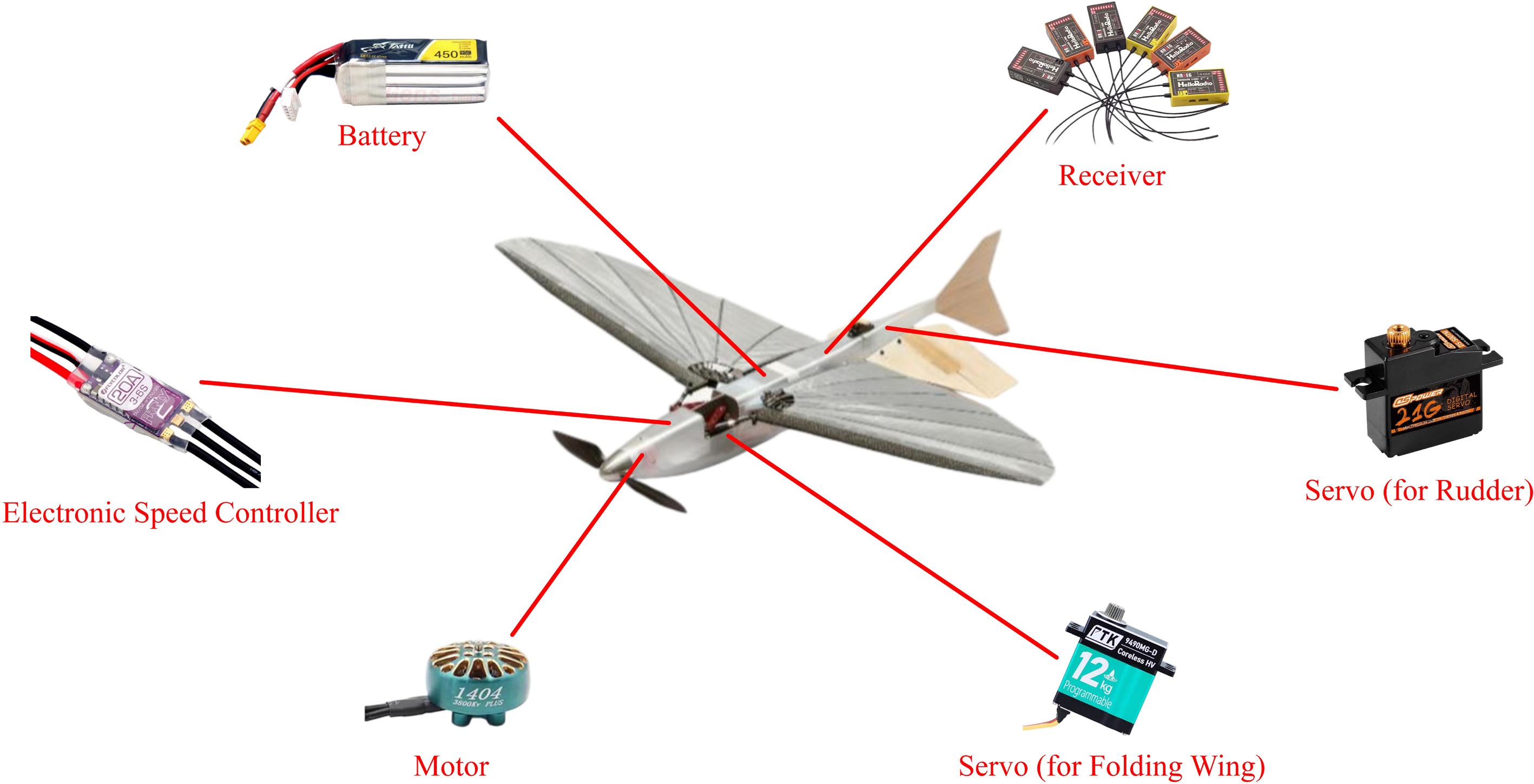
Figure 11.
Power system and electronic components of the aircraft prototype.
The wing leading edge adopts a sandwich composite D-box. The core material is lightweight polylactic acid (LW-PLA), which is 3D-printed and then wrapped with carbon-fiber cloth and cured under vacuum. The fishbone-shaped ribs are machined from carbon-fiber plates. A carbon-fiber rod shaft is bonded to the front end of each rib and reinforced with Kevlar thread wrapping. The tail surfaces are manufactured using a sandwich composite process: the core material is polymethacrylimide (PMI) foam sheet, Kevlar fabric is applied at the hinges, and both sides are covered with fiberglass cloth, followed by vacuum bag curing.
The wing is assembled using a dedicated assembly jig, which is manufactured by 3D printing. During assembly, the leading edge and the ribs are fixed onto the jig, and the clamping plates at the rotating shaft locations are secured with screws, ensuring that the leading edge and ribs are correctly positioned and held in place. Finally, the nylon fabric is laid over the skeleton and bonded. The wing assembly jig is shown in Fig. 12.
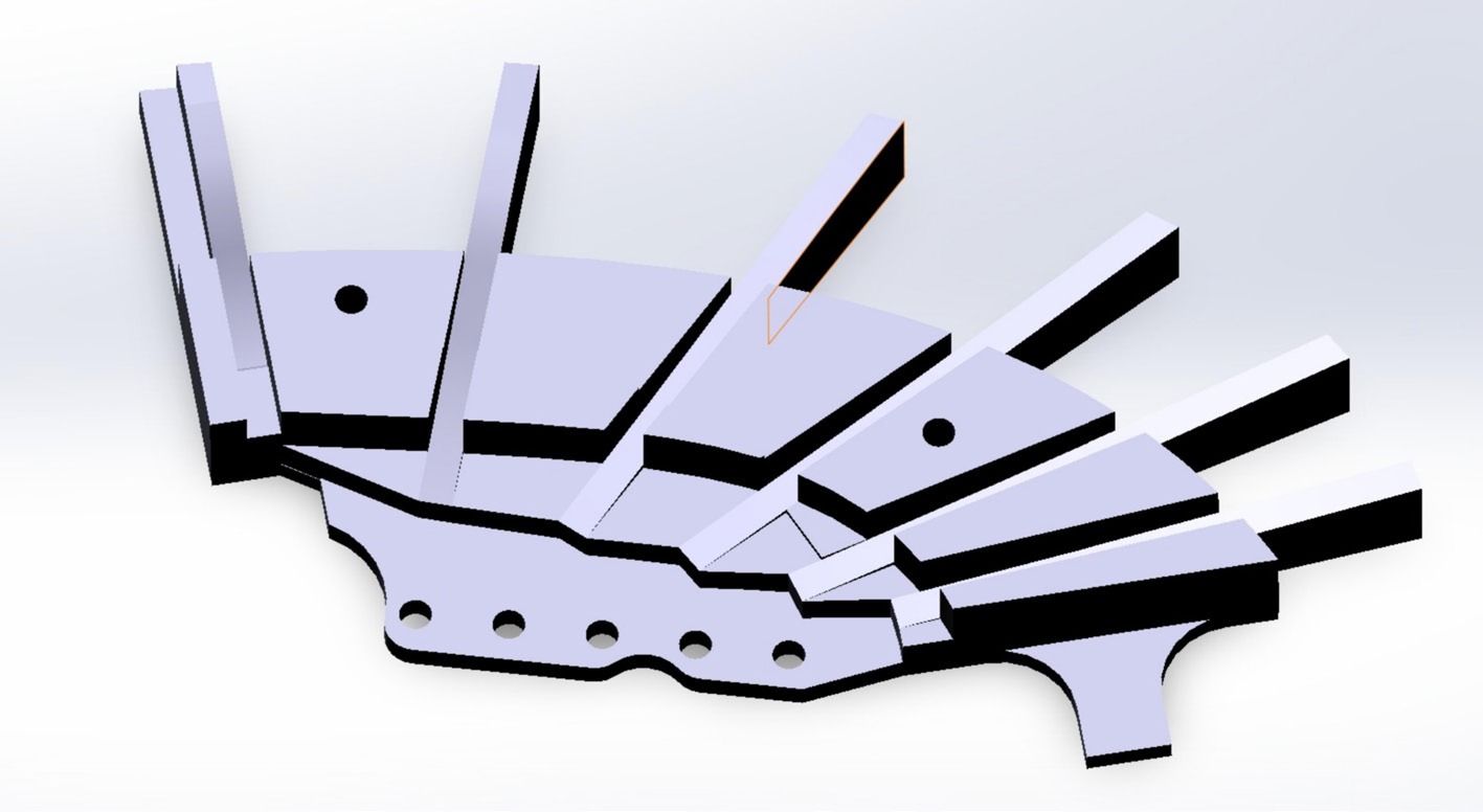
Figure 12.
Wing assembly jig design.
-
To verify the feasibility of the wing design, this study prepared a conventional configuration validation prototype with identical dimensions for flight tests to validate the membrane-frame foldable wing structure and the folding mechanism. The conventional configuration validation prototype integrates the same membrane-frame foldable wing and folding mechanism as the biomimetic configuration, and also employs differential tail surfaces for control. However, it is equipped only with a conventional vertical tail and a horizontal tail without anhedral (an inverted-T layout), focusing on validating the in-flight performance of the membrane-frame foldable wing and the actuation effectiveness of the folding mechanism.
This study conducted intensive flight tests and design iterations on the conventional configuration validation prototype. In the first flight test, the wing was designed without dihedral, and it was found that the overall aircraft exhibited poor lateral stability and was prone to roll divergence. After multiple design iterations, the wing dihedral angle was successively set to 10° and 5°, and finally determined to be 8° based on the lateral handling and stability feedback from the flight tests. During the flight tests, the membrane-frame foldable wing maintained its shape and the folding mechanism functioned well. After numerous flights, no performance-affecting deformation or displacement occurred in the membrane or the supporting ribs, confirming the aerodynamic and structural effectiveness of the wing and demonstrating the feasibility and reliability of the membrane-frame foldable wing structure and the folding mechanism, which met the design expectations. The conventional configuration validation aircraft is shown in Fig. 13.
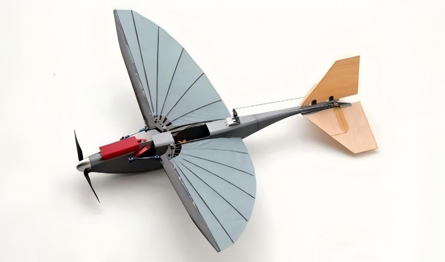
Figure 13.
The conventional configuration validation aircraft.
In subsequent flight tests, an anhedral angle was introduced on the horizontal tail. The aircraft's stability in all axes and its control response were essentially the same as those of the configuration without horizontal tail anhedral, preliminarily validating the stability and controllability of the biomimetic tail and differential control surface design.
After the design had matured, additional ballast was gradually added during flight tests to further evaluate the lift performance of the membrane-frame wing. The maximum gross flight weight reached 250 g, demonstrating that the wing design fully met the requirements.
Biomimetic configuration wind tunnel test
-
Based on the flight test results of the conventional configuration validation prototype, this study conducted wind tunnel tests on the biomimetic configuration prior to the biomimetic configuration validation flight tests[30,31]. The wind tunnel test procedure is shown in Fig. 14.
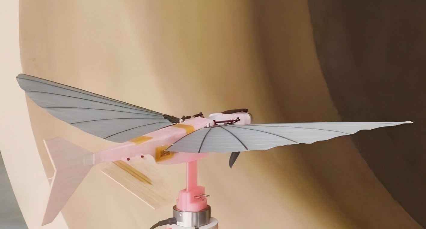
Figure 14.
Test model in the wind tunnel.
The main objective of the wind tunnel test was to measure the variations in lift, drag, and pitching moment with angle of attack and freestream velocity, and to preliminarily validate the full-aircraft lift-drag and pitch characteristics of the biomimetic configuration. Based on the flight test results of the conventional configuration validation prototype, the wind tunnel test was conducted at freestream velocities of 10 and 15 m/s, with the angle of attack ranging from −5° to 20°. Lift, drag, and moment data were recorded during both angle-of-attack sweep-up and sweep-down as repeated experiments to obtain the full-aircraft lift-drag and pitch characteristics. During the experiment, the buffeting of the membrane trailing edge and the supporting ribs in the membrane-frame foldable wing structure was also observed. The experimental results are shown in Fig. 15.
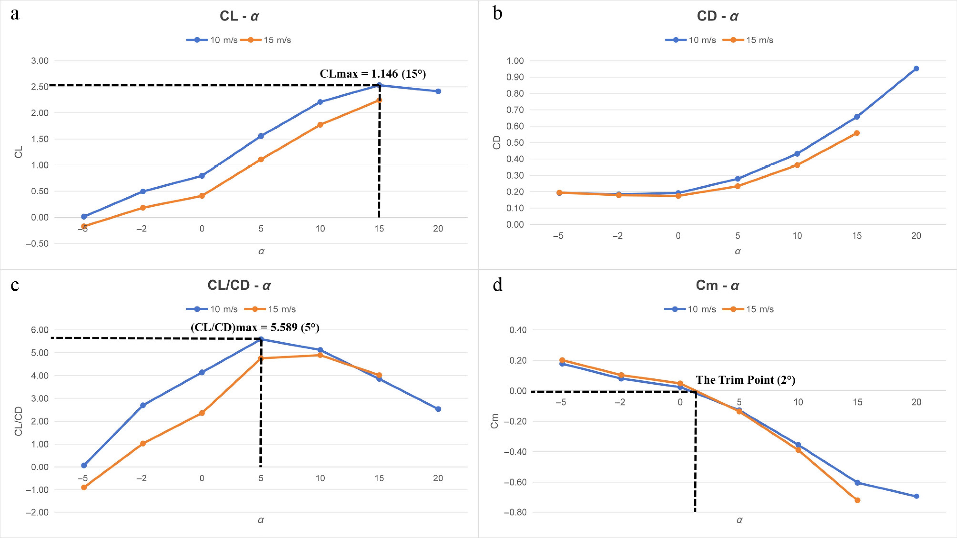
Figure 15.
Wind tunnel test results: (a) CL; (b) CD; (c) CL/CD; (d) Cm.
The experimental results show that at the cruise speed (10 m/s), the maximum lift coefficient of the full aircraft reaches 1.146, occurring at an angle of attack of 15°; the maximum lift-to-drag ratio reaches 5.589, occurring at an angle of attack of 5°. The longitudinal static stability is good, with the trim point appearing near an angle of attack of 2°. Both the maximum lift coefficient and the maximum lift-to-drag ratio are comparable to or even superior to those reported in previous aerodynamic studies on flying fish[5,6]. Meanwhile, observations during the experiment reveal that the membrane-frame foldable wing structure does not exhibit significant buffeting under various operating conditions, indicating good structural performance. Thanks to the leading-edge fairing design functioning as intended, no significant buffeting is observed on the membrane trailing edge even at commonly used angles of attack (2° to 10°), fully demonstrating the feasibility and reliability of this wing structure.
Biomimetic configuration validation flight test
-
The flight test of the conventional configuration and the wind tunnel test results of the biomimetic configuration met the design expectations. The maiden flight of the biomimetic configuration validation prototype was successful. Subsequently, multiple flight tests (including maneuverability flight tests) were completed, with a maximum gross flight weight of 270 g, and aerobatic maneuvers such as loops and inverted flight were accomplished.
As shown in Fig. 16, the flight speed was estimated by extracting consecutive frames from the recorded flight video and estimating the distance traversed. During the maximum level flight speed test, it was observed that the biomimetic configuration validation prototype traversed a distance of approximately 6 m within 0.2 s and maintained this speed during sustained flight. Based on this observation, the maximum level flight speed of the validation prototype is estimated to be approximately 30 m/s.
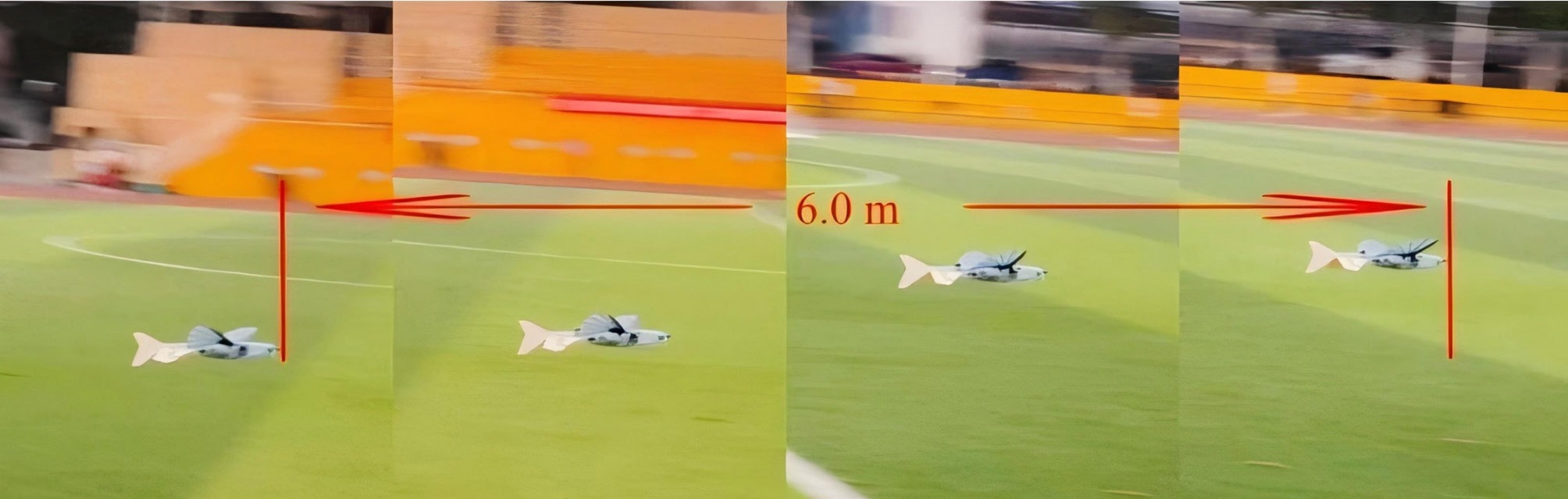
Figure 16.
Flight test (0.2 s continuous flight slices).
-
Taking the flying fish as the biomimetic prototype and addressing the two core shortcomings in existing biomimetic flying fish research—namely the scarcity of studies on pectoral-fin-inspired foldable wing design and on the close-coupled pectoral-pelvic fin configuration—this paper has completed the overall layout design, aerodynamic design, structural and mechanism design, as well as experimental validation of a flying fish-inspired aircraft with foldable pectoral fins and pelvic fins in a close-coupled configuration. A dedicated membrane airfoil that balances high lift and low moment characteristics, as well as a membrane-frame foldable wing that meets the requirements of large deployed area and small stowed envelope, have been developed. The study systematically resolves key technical challenges, including the poor trimming capability of the close-coupled pectoral-pelvic fin configuration, the structural stiffness and buffeting suppression of the membrane-frame foldable wing, and the efficient and reliable actuation of the folding mechanism.
(1) At the overall layout design level, the close-coupled configuration characteristics of the flying fish pectoral fins and pelvic fins are replicated. Through the synergistic design of wing dihedral and tail anhedral, a positive roll-yaw coupling effect is achieved. The elevon configuration resolves the handling stability challenge arising from the inability to install conventional ailerons on the flexible foldable wing. While ensuring high biomimetic fidelity, this approach achieves the synergistic optimization of aircraft stability in all axes and control response.
(2) At the aerodynamic design level, addressing the pain points of a short tail moment arm and significant wing downwash effects inherent to the close-coupled configuration, a dedicated membrane airfoil that balances high-lift and low-moment characteristics is obtained based on thin airfoil theory, through iterative optimization of a high-lift airfoil using a genetic algorithm and interpolation fusion with a low-moment airfoil. Combined with leading-edge fairing modification, this effectively solves the flow separation problem of thin airfoils, ultimately achieving an improvement in the overall aerodynamic performance of the aircraft. The resulting lift and lift-to-drag ratio are superior to typical results reported in existing biomimetic aerodynamic studies on flying fish.
(3) At the structural and mechanism design level, taking the radial fin-ray skeleton of the flying fish pectoral fin as the biomimetic blueprint, a membrane-frame foldable wing structure with carbon fiber supporting ribs mounted on distributed rotating shafts is designed. Together with a Kevlar fiber-reinforced connection method, this accurately replicates the biomimetic wing surface configuration while effectively suppressing membrane buffeting during flight. Furthermore, a four-bar crank-rocker mechanism designed based on Grashof's theorem achieves efficient 90° folding and deployment of the wing, thereby realizing the unified design goals of large lifting surface deployment and small envelope folding.
(4) At the experimental validation level, conventional configuration validation flight tests, biomimetic configuration wind tunnel tests, and biomimetic configuration validation flight tests were completed. The conventional configuration validation flight tests verified the reliability of the membrane-frame foldable wing structure and the folding mechanism, achieving stable flight at a gross weight of 250 g. The biomimetic configuration wind tunnel test results showed that the aircraft attains a maximum lift coefficient of 1.146 at a cruise speed of 10 m/s, a maximum lift-to-drag ratio of 5.589, excellent longitudinal static stability, and no significant wing surface buffeting under main operating conditions. The biomimetic configuration validation flight tests achieved stable flight at a gross weight of 270 g, with a maximum level flight speed of up to 30 m/s. These results comprehensively validate the rationality, feasibility, and superiority of the design.
The principal prototype of the flying fish-inspired aircraft with foldable pectoral fins and pelvic fins in a close-coupled configuration developed in this paper successfully validates the feasibility and superiority of the membrane-frame foldable wing design and the close-coupled pectoral-pelvic fin configuration based on flying fish biomimetics.
This work focuses on the design, manufacturing, and aerial flight phase of the aircraft. Further exploration will be conducted on the complete trans-medium locomotion process from underwater exit to aerial flight, addressing aspects such as the design of trans-medium takeoff and landing mechanisms and water-air transition dynamics modeling. Additionally, the aerodynamic, structural, and flight performance validation of the aircraft will be completed, with the aim of achieving true water-air cross-medium flight capability. This will enable a transition from 'partial biomimetics' to 'full biomimetics', thereby laying a more solid technical foundation for the engineering application of biomimetic cross-medium vehicles.
-
The authors confirm their contributions to the paper as follows: project supervision and academic guidance: Xue D; manuscript revision guidance and english proofreading: Li B; study conception and design: Guo Y, Hu Y; analysis and interpretation of results: Guo Y, Xu X, Hu Y, Zuo B, Yang F; manuscript preparation: Guo Y; flight test of the prototype: Xu X; overall design and manufacture of the prototype: Xu X, Hu Y; aerodynamic design and analysis of the prototype, airfoil optimization: Zuo B; data collection: Yang F. All authors reviewed the results and approved the final version of the manuscript.
-
The datasets generated during and/or analyzed during the current study are available from the corresponding author upon reasonable request.
-
The authors declare that they have no conflict of interest.
- Copyright: © 2026 by the author(s). Published by Maximum Academic Press, Fayetteville, GA. This article is an open access article distributed under Creative Commons Attribution License (CC BY 4.0), visit https://creativecommons.org/licenses/by/4.0/.
-
About this article
Cite this article
Guo Y, Xu X, Hu Y, Zuo B, Yang F, et al. 2026. Flying fish-inspired aircraft with foldable pectoral fins and pelvic fins in a close-coupled configuration. International Journal of Micro Air Vehicles 18: e020 doi: 10.48130/mav-0026-0021 

Flying fish-inspired aircraft with foldable pectoral fins and pelvic fins in a close-coupled configuration
- Received: 20 April 2026
- Revised: 20 July 2026
- Accepted: 31 August 2026
- Published online: 14 October 2026
Abstract: The flying fish, with foldable pectoral fins and a close-coupled pectoral-pelvic fin configuration, provides an ideal biomimetic prototype for foldable-wing aircraft. Existing research has focused on biological and aerodynamic characteristics for underwater prototypes, while studies on foldable-wing designs for aerial flight remain scarce. Key challenges include insufficient tail trimming in the close-coupled configuration and membrane wing susceptibility to flow separation and buffeting. To address these, this paper presents the aerodynamic and structural design and experimental validation of a flying fish-inspired aircraft with foldable pectoral fins and pelvic fins in a close-coupled configuration. The design replicates the fish's physiology: synergistic wing dihedral and tail anhedral resolve the lack of conventional ailerons on flexible wings. Based on thin airfoil theory, a membrane airfoil balancing high lift and low moment is obtained via a genetic algorithm and multi-airfoil interpolation, incorporating a leading-edge fairing to suppress flow separation. Inspired by the radial fin-ray skeleton, a membrane-frame foldable wing with carbon-fiber supporting ribs on distributed shafts and a four-bar crank-rocker mechanism achieves a large deployed area and a small stowed envelope. Wind tunnel and flight tests showed a maximum lift coefficient of 1.146 and a lift-to-drag ratio of 5.589 at 10 m/s, exceeding the aerodynamic performance of biological flying fish. During testing, no significant buffeting was observed, and the folding mechanism demonstrated high reliability. The biomimetic prototype achieves stable flight and maneuvers at 270 g, with a maximum speed of 30 m/s. This work validates the close-coupled pectoral-pelvic fin configuration and membrane-frame foldable wing, establishing a theoretical and technical foundation for next-generation biomimetic wings and cross-medium vehicles.