











-
Unmanned Aerial Vehicles (UAVs) have rapidly advanced over the past two decades, resulting in a wide range of aerial platforms optimized for diverse missions. UAVs are generally classified into fixed-wing and rotary-wing aircraft, each offering distinct advantages and design challenges, while a smaller subset includes hybrid and flapping-wing systems. Fixed-wing UAVs are preferred for long-endurance missions and large-area monitoring due to their aerodynamic efficiency and extended flight range[1,2]. Rotary-wing UAVs enable vertical take-off and landing, stationary flight, and high maneuverability, making them essential for tasks such as inspection, surveillance, and aerial manipulation. Within this category, two main types exist: helicopters and multirotors. Helicopters typically employ a main–tail rotor configuration, which involves complex mechanical and aerodynamic interactions[3,4]. Multirotors use multiple fixed-pitch rotors, usually in symmetric layouts, providing mechanical simplicity, reliability, and ease of maintenance. Unconventional designs have been explored to enhance maneuverability, efficiency, and operational flexibility[5,6]. Multirotor UAVs represent one of the most versatile categories due to their agility and ability to perform diverse missions, ranging from inspection and surveillance to payload delivery[7] and aerial manipulation[8].
Despite their maturity and broad adoption, multirotors remain a highly active area of research, driven by persistent challenges related to stability, energy efficiency, and mission autonomy. These systems are inherently unstable and exhibit strong nonlinear dynamics, necessitating advanced control strategies and precise dynamic modeling to achieve reliable performance under varying flight conditions[9,10]. Conventional configurations, such as quadrotors, hexarotors, and octorotors, consist of planarly and symmetrically arranged rotors. Quadrotors remain the most common design, covering a broad spectrum of mission requirements. Hexarotors and octorotors are frequently employed when higher payload capacity or increased operational safety is required due to propulsion redundancy.
Commercial solutions already cover many of these conventional configurations, such as the DJI Matrice 600 Pro hexarotor[11]. However, high energy consumption continues to limit flight endurance, motivating research into structural optimization, lightweight airframes, and energy-efficient propulsion systems[12,13]. Beyond traditional fixed-geometry designs, novel configurations have been proposed to enhance maneuverability and efficiency. Examples include variable-geometry configurations, often referred to as tilting-rotor, investigated in[14,15]. Commercial multirotors, such as DJI platforms, typically employ proprietary architectures that restrict modularity and customization. In contrast, open-source systems based on autopilots such as Pixhawk have facilitated research-oriented development, enabling dynamic flight testing, control algorithm validation, and mission-level system design[16].
In addition to commercial platforms, there has been a growing trend toward open-source projects for multirotor UAV design and control[17]. From a design perspective, research in this field focuses both on enhancing individual hardware components, such as propulsion, energy, and control systems, and on integrating them into cohesive, custom-built UAV platforms. Given that multirotors inherently exhibit high energy consumption, careful selection of propulsion and energy subsystems remains crucial for achieving the desired system performance[18]. Several studies have explored the development of custom UAV solutions for educational and training purposes, aiming to provide low-cost, portable, and easily maintainable platforms[19−22]. Beyond commercial airframes, advances in manufacturing technologies have enabled the creation of fully customized designs that integrate propulsion, energy, and control components into functional assemblies[23−25]. Furthermore, several research efforts have investigated airframe structures with unique mechanical characteristics, particularly foldable and morphing designs[26−28].
Advances in rapid prototyping technologies, particularly Additive Manufacturing (AM), have significantly accelerated the design and fabrication of customized UAV structures. Fused Deposition Modeling (FDM) is the most widely adopted AM technology due to its accessibility, low cost, and versatility. It has been applied across a broad range of UAV elements, from functional propellers[29] to complete airframe structures. Considering the dynamic nature of multirotor flight, the design of such airframes plays a critical role in ensuring structural integrity. Consequently, various studies have investigated topology optimization, generative design[30], and simulation-based methods. In addition to standard thermoplastic materials, employing composite materials has been explored to improve strength-to-weight ratios and enhance overall mechanical performance[31,32]. Beyond the design domain, AM technologies have also transformed the organization of UAV production[33−35].
Despite these advances, existing approaches typically address only isolated aspects of UAV modularity and reconfigurability. Modular and adjustable airframes enable geometric adaptation, but often lack integrated electrical interfaces, requiring manual assembly and rewiring. As a result, rapid field reconfiguration, seamless subsystem interchangeability, and efficient adaptation to varying mission requirements remain limited. In particular, the integration of energy subsystems is rarely addressed from a modular perspective, despite its critical role in endurance and operational flexibility. These limitations also constrain the development of higher-level functionalities, such as automated battery replacement.
The primary contribution of this work is the design of a novel modular and scalable multirotor airframe featuring rapid plug-and-play reconfigurability at both the mechanical and electrical levels. The platform is built around three core modules: the battery module (BM), rotor arm modules (RAMs), and central hub module (CHM). Modules are interconnected through dedicated mechanical and electrical interfaces that ensure reliable and repeatable integration. A parametric design approach enables scalability in terms of system power and energy capacity, achieved through the selection of different RAMs and BMs. Two key mechanisms are introduced: a RAM plug-in interface and a BM slide-in interface with integrated energy and signal connection. Together with the CHM, these interfaces enable the creation of a modular UAV kit consisting of a common platform and interchangeable rotor arm and BMs. This allows the same airframe to be rapidly reconfigured for different operating requirements, such as lightweight outdoor flights, indoor experiments requiring companion computers and additional onboard sensors, or configurations with extended flight endurance. Such flexibility makes the platform particularly suitable for engineering education and research laboratories, where a single UAV platform can support a wide range of experimental scenarios without requiring multiple dedicated airframes. Furthermore, the standardized interfaces establish a foundation for future extensions toward automated battery replacement and fully autonomous UAV operation.
A secondary contribution is the development and validation of a complete manufacturing and assembly workflow that integrates additive and subtractive manufacturing technologies. This provides a reproducible and experimentally validated framework for producing UAV components, and facilitates their potential open-access distribution, thereby supporting research and education. This contribution is further complemented by an analysis of mass distribution and energy consumption during hovering, offering quantitative insight into system-level performance. An extensive experimental evaluation, including hovering, horizontal flight, and autonomous waypoint tracking, demonstrates reliable operation under realistic conditions and confirms the practical feasibility of the proposed modular design. Preliminary results of this research were presented in[36], while this paper significantly extends the initial concept.
This paper is organized into six sections as follows. In section Modeling and characterization of the multirotor UAV system, it introduces the overall system model and characteristics of the proposed modular multirotor UAV platform, consisting of the BM, RAM, and CHM modules. In section Design of a novel modular, scalable, and rapid-reconfigurable airframe, it presents the novel modular, scalable, and rapidly reconfigurable airframe concept. In section Manufacturing of airframe and assembly into multirotor modules details the manufacturing workflow and assembly, it includs the mass distribution and hovering-power analysis. In section Performance evaluation of the proposed multirotor UAV platform, it presents performance evaluation through three experimental case studies. Finally, in section Conclusions, it provides concluding remarks.
-
This section outlines the fundamental parameters of the multirotor UAV system that directly influence the design of the modular and reconfigurable platform. Understanding the interdependence between system- and subsystem-level characteristics is essential for assessing their impact on overall performance and for making informed design decisions. Accordingly, a dynamic model of the UAV is presented as a unified representation of the vehicle dynamics. Based on this general formulation, particular attention is subsequently devoted to the propulsion-related components, accompanied by a detailed characterization of the propulsion and energy subsystems. Together, these models establish an analytical framework for evaluating efficiency and endurance in the subsequent stages of the design process.
Multirotor UAV system model and parameters
-
As rigid bodies operating in three-dimensional space, multirotor UAVs possess six degrees of freedom (DOFs), comprising three translational velocities
$ {\bf{v}}={[\begin{array}{ccc}u & v & w\end{array}]}^{\text{T}} $ $ {{ ω}}={[\begin{array}{ccc}p & q & r\end{array}]}^{\text{T}} $ $ {\mathcal{F}}^{\text{B}}{\{O}_{\text{B}},{X}_{\text{B}},{Y}_{\text{B}},{Z}_{\text{B}}\} $ $ m\dot{\bf{v}}+{ω}\times \left(m{\bf{v}}\right)={\bf{f}}+{\bf{g}}_{\text{B}}+{\bf{f}}_{\text{D}}+{\bf{d}}_{\text{F}}, $ where
$ m $ $ {\bf{f}}={[\begin{array}{ccc}{f}_{\text{X}} & {f}_{\text{Y}} & {f}_{\text{Z}}\end{array}]}^{\text{T}} $ $ {\bf{g}}_{\text{B}} $ $ {\bf{f}}_{\text{D}} $ $ {\bf{d}}_{\text{F}} $ $ {\bf{I}}\dot{{ω}}+{ω}\times\left({Iω}\right)={{τ}}+{\bf{o}}_{\text{B}}+{{τ}}_{\text{D}}+{\bf{d}}_{\text{Τ}}, $ where
$ \bf{I} $ $ \bf{I} $ $ {{τ}}={[\begin{array}{ccc}{\tau }_{\phi } & {\tau }_{\theta } & {\tau }_{\psi }\end{array}]}^{\text{T}} $ $ {\bf{o}}_{\text{B}} $ $ {{τ}}_{\text{D}} $ $ {\bf{d}}_{\text{T}} $ In steady-state hovering conditions, the attitude angles and angular rates are zero, and the vertical component of the propulsion force balances gravity, i.e.,
$ {f}_{\text{Z}}=mg $ To control translational and rotational motion, propulsion forces and moments are generated according to the UAV's propulsion configuration. A multirotor configuration consists of
$ N $ 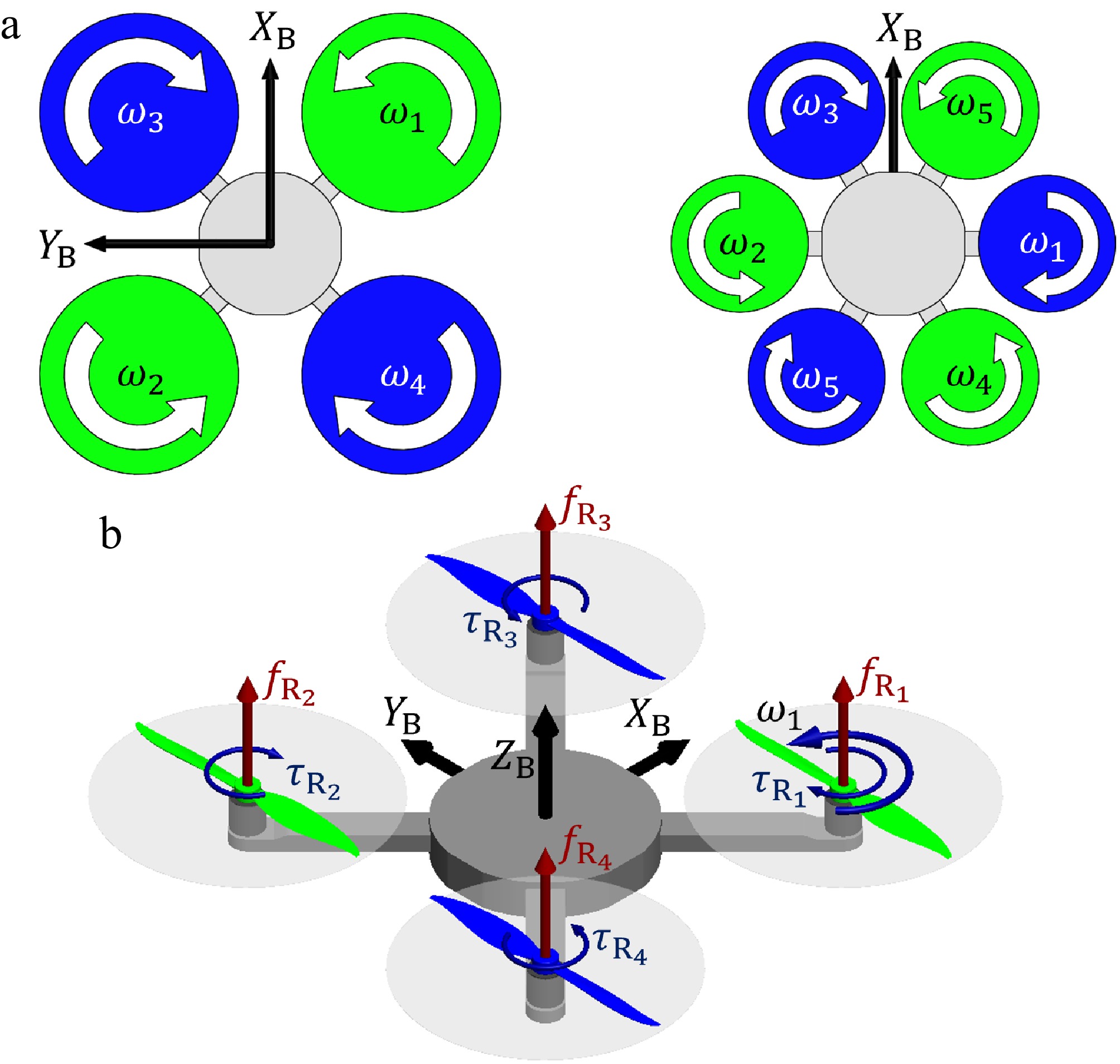
Figure 1.
Conventional multirotor configurations: (a) symmetric rotor layout with an even number of rotors; (b) conventional quadrotor X-configuration.
For the purposes of modeling and preliminary design, the aerodynamic forces and moments generated by each propulsion unit are assumed to consist solely of a thrust force and an associated drag torque. The individual rotor thrust forces are collected in the vector
$ {\bf{f}}_{\text{R}}={\left[\begin{array}{cccc} {f}_{{{\text{R}}_{1}}} & {f}_{{{\text{R}}_{2}}} &\cdots & {f}_{{{\text{R}}_{N}}} \end{array}\right]}^{\text{T}}, $ while the corresponding rotor drag torques are collected in the vector
$ {{τ}}_{\text{R}}={\left[\begin{array}{cccc} {\tau }_{{{\text{R}}_{1}}} & {\tau }_{{{\text{R}}_{2}}} & \cdots & {\tau }_{{{\text{R}}_{N}}} \end{array}\right]}^{\text{T}}. $ The geometric arrangement of the UAV rotors is captured through mapping matrices that transform the individual rotor thrusts and drag torques into the net force and moment vectors acting on the vehicle:
$ \bf{f}=\mathbf{H }{\mathbf{f}}_{\text{R}}, $ $ {{τ}}={ Ξ}{\bf{f}}_{\text{R}}+{\bf{H}}{{τ}}_{\text{R}}. $ Here,
$ \bf H $ $ {Ξ} $ $ \bf H $ $ {Ξ} $ $ {\bf H}{{τ}}_{\text{R}} $ To explicitly define the geometry, each rotor
$ i $ $ {{ξ}}_{{{\text{R}}_{i}}} $ $ {{η}}_{{{\text{R}}_{i}}} $ $ {\bf{H}}=\left[\begin{array}{ccc} {{η}}_{{{\text{R}}_{1}}} & \cdots & {{η}}_{{{\text{R}}_{N}}} \end{array}\right] $ while the moment mapping matrix is constructed by combining the rotor positions and orientations using the skew-symmetric operator (
$ {\bf a}\times {\bf b}={\bf S}({\bf a}){\bf b} $ $ {{Ξ}}=\left[\begin{array}{ccc} \bf{S}\left({{ξ}}_{{{\text{R}}_{1}}}\right){{η}}_{{{\text{R}}_{1}}} & \cdots & \bf{S}\left({{ξ}}_{{{\text{R}}_{N}}}\right){{η}}_{{{\text{R}}_{N}}} \end{array}\right]. $ This formulation provides a compact and general representation of the propulsion arrangement, with further details available in[38]. For the conventional planar configurations considered in this work, the rotor orientation vectors are defined as unit vectors, resulting in an underactuated system due to the reduced rank of the allocation matrix. The key geometric parameter is the UAV arm length (
$ l $ $ N $ $ {d}_{\text{p}} $ Propulsion configuration characterization
-
The propulsion configuration represents a critical aspect of multirotor UAV design, as it directly affects efficiency, flight stability, and overall vehicle performance. The electric propulsion system consists of
$ N $ $ {K}_{\text{v}} $ Table 1. Summary of propulsion kits integrated into the modular UAV platform.
Air Gear set Propeller BLDC ESC Model $ {d}_{\text{p}} $ Model $ {K}_{\text{v}} $ Imax LiPo cell AG200 T6535 6.5" AIR2205 2,000 15 A 2-3S AG355 MF9545 9.5" AIR2213 1,000 20 A 3-4S AG450 T1045 10" AIR2216 880 20 A 3-4S The performance characteristics of each EPU were experimentally evaluated in order to capture the relationship between rotor angular velocity
$ \omega $ $ {f}_{\text{R}} $ $ {\tau }_{\text{R}} $ $ {f}_{\text{R}} $ $ {\tau }_{\text{R}} $ $ \omega $ $ {f}_{\text{R}}\left(\omega \right)={k}_{\text{f}}{\omega }^{2}, $ $ {\tau }_{\text{R}}\left(\omega \right)={k}_{\text{τ}}{\omega }^{2}, $ where
$ {k}_{\text{f}} $ $ {k}_{\text{τ}} $ 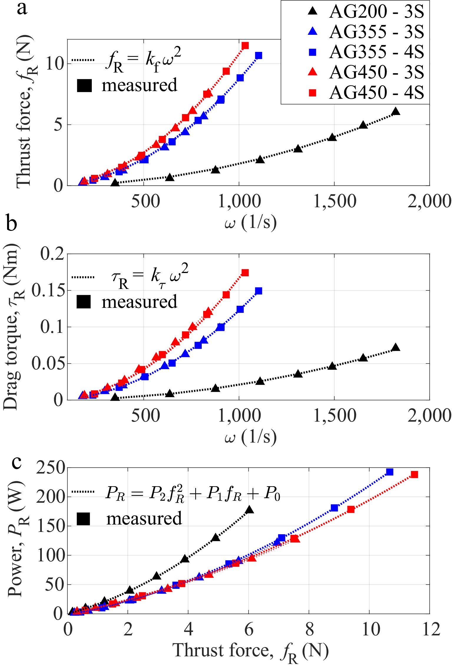
Figure 2.
Experimental characterization for the considered propulsion setups: (a) thrust force as a function of rotor angular velocity; (b) drag torque as a function of rotor angular velocity; (c) electrical power as a function of thrust force. Colored markers represent the experimentally measured data, while the corresponding dotted lines represent the fitted analytical models.
Based on these approximations, a simplified mapping between the individual rotor angular velocities and the resulting total propulsion force and torque acting on the vehicle can be defined. This formulation highlights that, for conventional planar multirotor configurations, the force and torque distribution depends jointly on the propulsion coefficients and the geometric layout, defined by the number of rotors (
$ N $ $ l $ In addition to aerodynamic forces and moments, the experimental measurements also included electrical quantities, enabling an empirical characterization of the thrust–power relationship. Since multirotor UAVs typically exhibit high energy consumption, this relationship represents a critical factor in both propulsion system design and battery selection. As shown in Fig. 2c, the experimentally obtained thrust–power characteristics indicate that larger propeller diameters generally improve propulsion efficiency by reducing the electrical power required to generate a given thrust. However, this efficiency gain comes at the cost of increased propulsion system mass, leading to inherent trade-offs in UAV sizing and performance. The total mass of the vehicle is strongly influenced by the selected propulsion and energy storage components, which are closely interdependent, with the battery contributing the largest share. Accordingly, three BM configurations based on lithium-polymer (LiPo) batteries are considered, as summarized in Table 2, enabling flexible trade-offs between flight endurance, payload capacity, and agility. The polynomial power model derived from the experimental data,
$ {P}_{\text{R}}={P}_{2}{{{f}_{\text{R}}}}^{2}+{P}_{1}{f}_{\text{R}}+{P}_{0}, $ provides a compact representation of the thrust–power characteristics and enables energy consumption estimation in simulation. This model supports efficient optimization of the combined propulsion–battery system during the conceptual and preliminary design stages.
Table 2. Summary of the parametrically designed battery module (BM) and rotor arm module (RAM) configurations considered in the proposed modular UAV platform.
BM
config$ {C}_{\text{bat}} $ (Ah) $ S $ $ {m}_{\text{bat}} $ (g) BM dimensions (mm) $ {m}_{\text{BM}} $ (g) RAM
config$ {d}_{\text{p}} $
(")$ {K}_{\text{v}} $
(rpm/V)$ {m}_{\text{EPU}} $ (g) RAM dimensions (mm) $ {m}_{\text{RAM}} $ (g) L W H L W H BM_C1 5 3 355.2 158 58 54.4 408 RAM_C1 6.5 2,000 42 144 30 15 90.3 BM_C2 10 3 569.2 172 75 58.4 636 RAM_C2 9.5 1,000 70.6 184 30 15 130.9 BM_C3 6.75 4 636.1 187 64 68.4 704 RAM_C3 10 880 90.4 189 30 15 152.3 -
The main contribution of this work is the design of a novel modular and scalable airframe featuring rapid plug-and-play reconfigurability. Building upon the system modeling and propulsion characterization presented in Section II, the proposed design supports a range of propulsion configurations and payload requirements while maintaining structural simplicity and efficient integration of propulsion and energy subsystems, enabling fast field deployment. A parametric design approach enables scalable adaptation to different mission requirements without requiring a complete redesign. The modular architecture comprises three key modules: the BM, the CHM with integrated landing elements, and the RAMs interconnected through integrated mechanical, electrical, and signal interfaces.
The proposed airframe incorporates two core mounting mechanisms: a plug-in interface for attaching the RAMs to the CHM and a slide-in interface for mounting the BMs to the CHM, both with integrated electrical connections. The assembled CAD model of the quadrotor airframe is shown in Fig. 3a, while Fig. 3b presents an exploded view highlighting the modular separation.
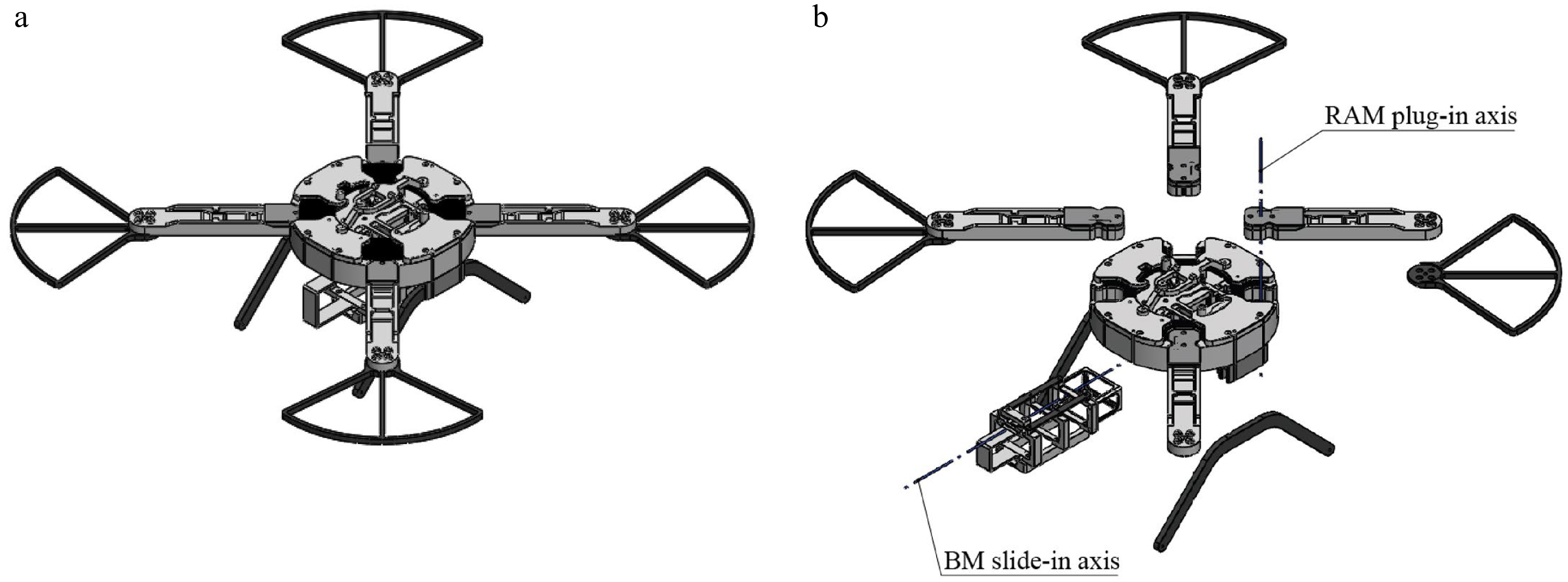
Figure 3.
CAD model of the quadrotor airframe: (a) all modules integrated in a ready-to-fly configuration; (b) exploded view showing the modular separation and landing-gear elements.
The proposed modular platform comprises three BM and three RAM configurations developed using a common parametric design methodology. Their principal design parameters, geometric characteristics, and masses are summarized in Table 2. The following subsections provide a detailed description of the adopted parametric design methodology and manufacturing considerations, from which the final module geometries and masses are derived.
Parametric design of the battery module
-
In the broader design context, the proposed airframe platform is designed to support automated battery replacement through a slide-in interface, realized with carbon-fiber guide rails and additively manufactured housing components. The selected manufacturing technologies are low-cost and easy to implement, facilitating rapid prototyping and broad applicability. Together with the battery, these elements form the BM, with an exploded view of the BM airframe parts shown in Fig. 4. The primary design objective is to minimize the mass of the BM airframe assembly, keeping it below 15% of the battery's total mass, while ensuring sufficient durability to withstand the plug/unplug cycles.
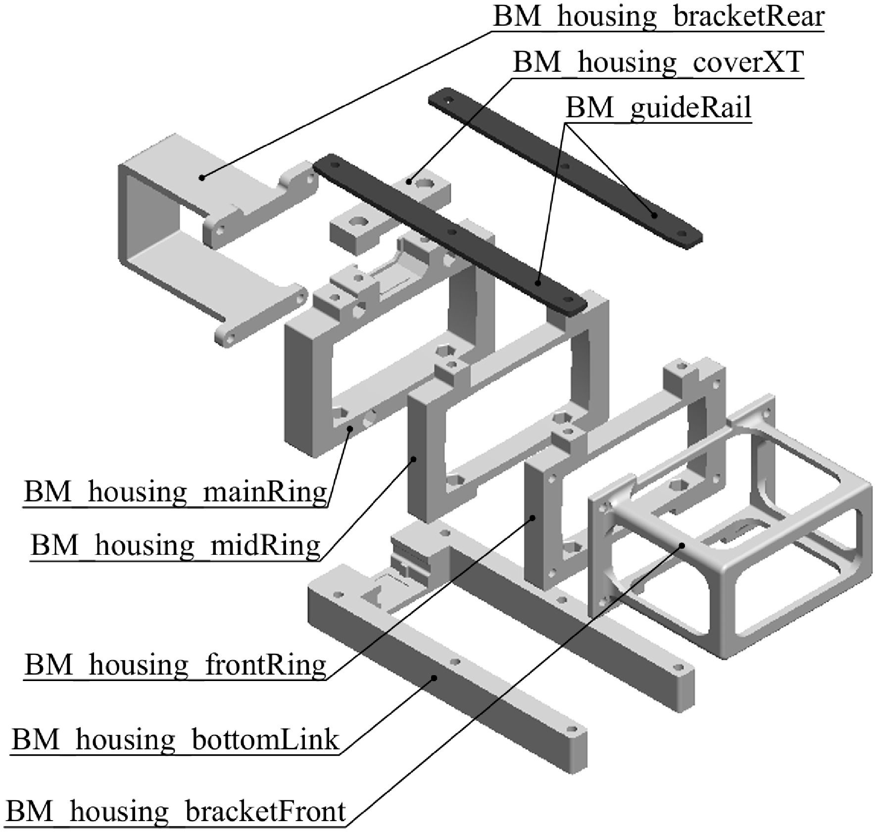
Figure 4.
Exploded view of the parametric BM airframe, consisting of housing and guideRail parts.
The airframe parts of the BM_housing, highlighted in Fig. 4, are based on a parametric design intended for FDM manufacturing across all BM configurations. The housing consists of a parametric mainRing integrating the XT60 battery connector, along with midRing and frontRing variants that differ only in their mounting interfaces. The bracketFront and the bracketRear securely hold the battery in place. Other housing parts, namely coverXT and bottomLink, alongside the BM_guideRail parts, retain identical overall dimensions across all battery configurations. However, the geometry of the bottomLink slot for the balance connector is adapted to accommodate either 3-cell or 4-cell batteries.
All airframe parts feature hexagonal slots for M2 self-locking nuts, ensuring reliable fastening. The housing integrates the required electrical interfaces, comprising the XT60 connector for energy transfer to the UAV, along with a dedicated charging connector. The proposed parametric design approach enables adaptation of the BM to different battery configurations while preserving the standardized slide-in interface with the CHM. The three BM configurations summarized in Table 2 illustrate this approach. Compatibility with different battery dimensions is achieved by parametrically modifying the ring and bracket elements, while preserving the guideRail geometry and standardized external interface. This ensures full mechanical and electrical compatibility across the platform.
Design of the central hub module and landing elements
-
The CHM represents the structural and functional core of the multirotor UAV, integrating the primary mechanical interfaces, electrical distribution elements, and mounting provisions for onboard subsystems. Its main airframe part, the CHM_centralHousing, is shown as part of the exploded CHM assembly in Fig. 5. The housing adopts a circular geometry with flat outer surfaces, facilitating accurate calibration and alignment of the flight controller (FC) and its onboard sensors. The selected housing diameter reflects a balanced design trade-off: increasing the diameter improves overall platform structural stiffness and provides additional space for modular subsystem integration, but at the expense of increased mass and aerodynamic drag.
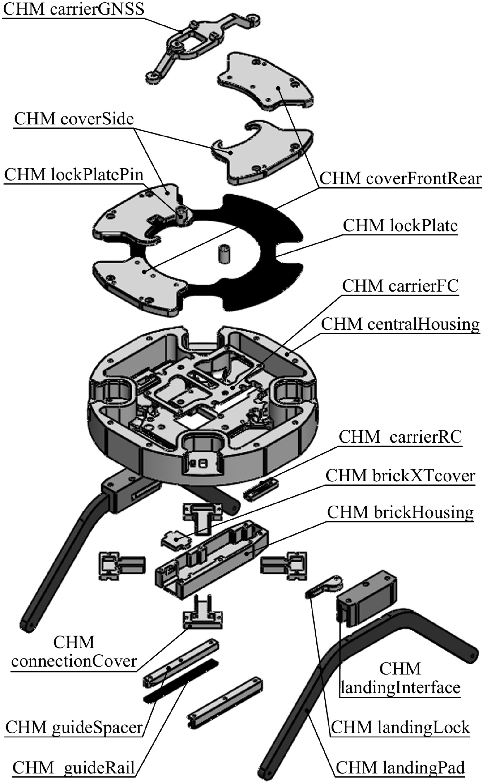
Figure 5.
Exploded view of the CHM airframe assembly.
Building directly on the BM described in the previous subsection, the CHM integrates a complementary slide-in interface that enables automated battery replacement. This interface is realized through secure attachment of the battery guide rails to the central housing. The housing geometry is further adapted to accommodate the power brick elements associated with this interface, with dimensions matched to the standardized power brick module and aligned with the geometry of the BM. To ensure correct alignment and repeatable engagement, the guide rails are mounted using M2 screws together with CHM_guideSpacer parts. The CHM_brickHousing, which accommodates the power brick module supplying the FC, is similarly attached to the central housing, ensuring seamless mechanical and electrical integration with the BM. In addition to the slide-in functionality, the central housing incorporates dedicated mounting features for internal subsystems, such as the FC, while auxiliary mounting interfaces enable the integration of mission-specific components such as cameras, sensors, or other payloads, enhancing the versatility of the platform while maintaining a compact and structurally efficient layout.
The second key functional mechanism integrated into the CHM is the plug-in interface for the RAMs. The housing incorporates a geometrically matched interface that ensures precise positioning of each rotor arm and constrains motion in two axes within the UAV horizontal plane. Locking along the third axis is achieved using the rotating CHM_lockPlate, which secures the inserted rotor arms once rotated into the locked position. Manual actuation is provided by the CHM_lockPlatePin, while cover parts protect the mechanism and guide its rotation. Additionally, cover parts provide mounting interfaces for auxiliary components, such as the CHM_carrierGNSS, as shown in Fig. 5. The plug-in sequence is illustrated in Fig. 6, showing the lockPlate in the unlocked position (Fig. 6a), followed by insertion of the RAMs (Fig. 6b), and finally the locked configuration with the arms fully constrained (Fig. 6c).
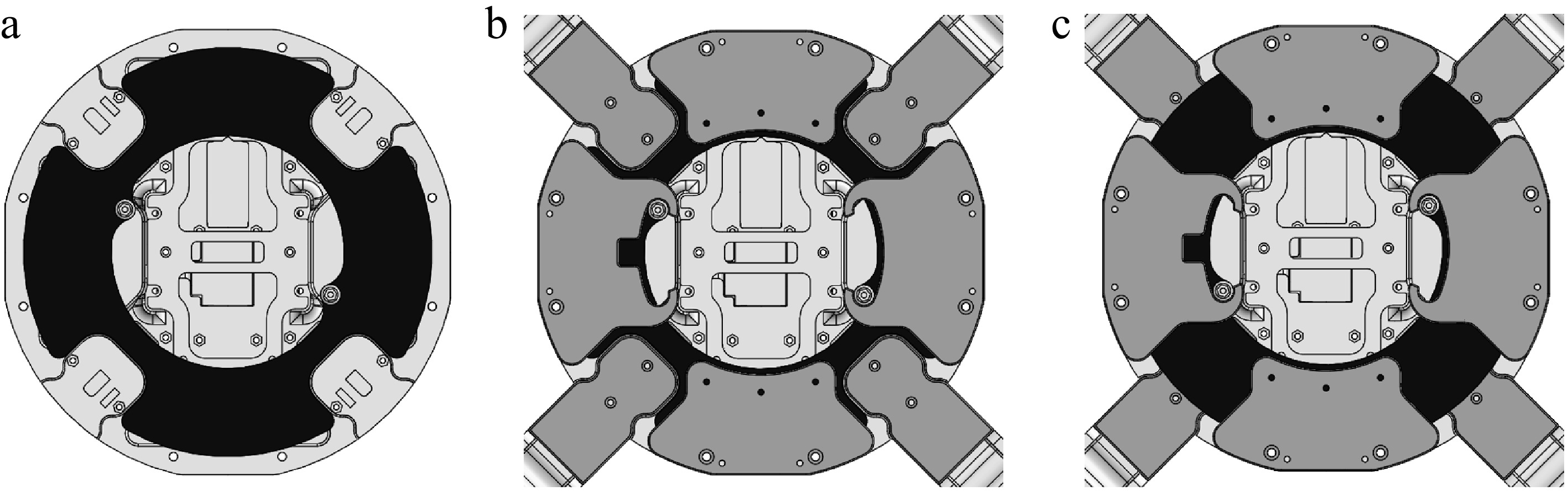
Figure 6.
Illustration of the RAM plug-in sequence: (a) lockPlate in the unlocked position, (b) RAMs inserted into the housing interface, and (c) lockPlate rotated to secure the rotor arms along all three axes.
Finally, the CHM integrates mounting interfaces for the landing gear, attached to the bottom plane of the central housing via the CHM_landingInterface parts. These interfaces constrain the landing pads along two axes, while locking along the third axis is achieved using a lever-based CHM_landingLock part, mounted on each interface, enabling rapid tool-free attachment and removal. Since the CHM_landingPad parts are subjected to the highest structural loads during landing, they are designed for manufacturing using continuous fiber fabrication (CFF) AM technology to achieve high strength at low mass. The design of these load-bearing parts is supported by established studies on AM process parameters[40,41].
Parametric design of the rotor arm module
-
Unlike the landing gear, which is primarily exposed to impact loads during landing, the RAM functions as a key structural airframe module. The main airframe assembly part, the RAM_rotorArm, is continuously subjected to mechanical loads induced by the propulsion units during flight. The objective is to develop a lightweight yet sufficiently stiff and durable RAM solution that satisfies the mechanical requirements of the considered propulsion configurations. A parametric design approach is applied to balance the design requirements of structural performance, low mass, manufacturability, and modularity while ensuring scalable adaptation of the rotor arm geometry to different propulsion configurations without major redesigns. In this work, three RAM_rotorArm configurations are parametrically designed for three electric propulsion setups, as summarized in Table 1.
The rotorArm geometry incorporates several design features to enable modular integration and is defined by two functional ends. At the inner end, the connection to the CHM is realized through a plug-in interface whose geometry is fully matched to the corresponding CHM interface features, ensuring precise, rigid, and repeatable positioning. This interface also integrates an XT30 connector for energy distribution and dedicated signal connectors, enabling seamless electrical and communication links between the propulsion units and the CHM. Both the CHM interface and the rotor arm geometry are provided in clockwise (CW) and counterclockwise (CCW) variants to ensure correct motor rotation orientation. The central section provides internal space for insertion of the ESC. At the outer end, the rotor arm incorporates the motor mounting interface and an optional guard element, both secured using M3 screws. The motor mounting layout is parametrically defined to match the stator geometry, ensuring compatibility across different propulsion setups. The outer-end geometry further includes a spacer that elevates the motor to enhance heat dissipation.
Two AM technologies, FDM and CFF, were initially considered for the fabrication of the RAM_rotorArm. FDM was selected as the primary manufacturing method due to its adequate mechanical performance for the considered load cases, lower cost, and ease of implementation. The design goal is to ensure that the RAM_rotorArm satisfies the mechanical requirements imposed by dynamic flight loads while remaining lightweight. While geometric design has the dominant influence on structural performance, printing parameters such as wall thickness and infill also significantly affect stiffness and load-bearing capacity.
Due to the anisotropic nature of FDM-manufactured parts, combined with the geometric complexity of the RAM_rotorArm, experimental testing was conducted to validate the design and to identify suitable printing parameters. In the test setup, one end of each rotor arm was rigidly clamped to replicate the CHM plug-in interface, while loads ranging from 300 to 1,200 g were applied at the rotor axis. Static deflection was measured using a dial gauge. The evaluated configurations include a reference rotor arm from the commercially available S500 airframe and three RAM_rotorArm setups based on the RAM_C2 geometry. Two FDM-manufactured setups employed an identical infill density of 20% with two and four perimeter walls, respectively, while the third was manufactured using CFF with stock matrix parameters (37% infill density and two wall layers) and continuous fiberglass reinforcement (2 × 0.4 mm). The corresponding rotor arm masses are 44.9 g (S500 reference), 29.85 g (FDM – Setup 1), 35.4 g (FDM – Setup 2), and 37.7 g (CFF – Setup 3).
The experimental results are summarized in Fig. 7, where the measured static deflection is presented as a function of the applied load. The comparison provides quantitative insight into the influence of manufacturing technology and printing parameters on structural stiffness. Increasing the number of printed walls in the FDM configurations results in only a moderate reduction in static deflection relative to the associated increase in mass. However, the additional walls improve the local strength of bolted interfaces used for motor and rotor guard attachment, and were therefore adopted in the proposed design. Compared with the reference S500 rotor arm, the resulting RAM_rotorArm achieves lower mass and reduced static deflection. These findings guided the refinement of the RAM_rotorArm geometry and established a baseline for future refinement using computational design methods.
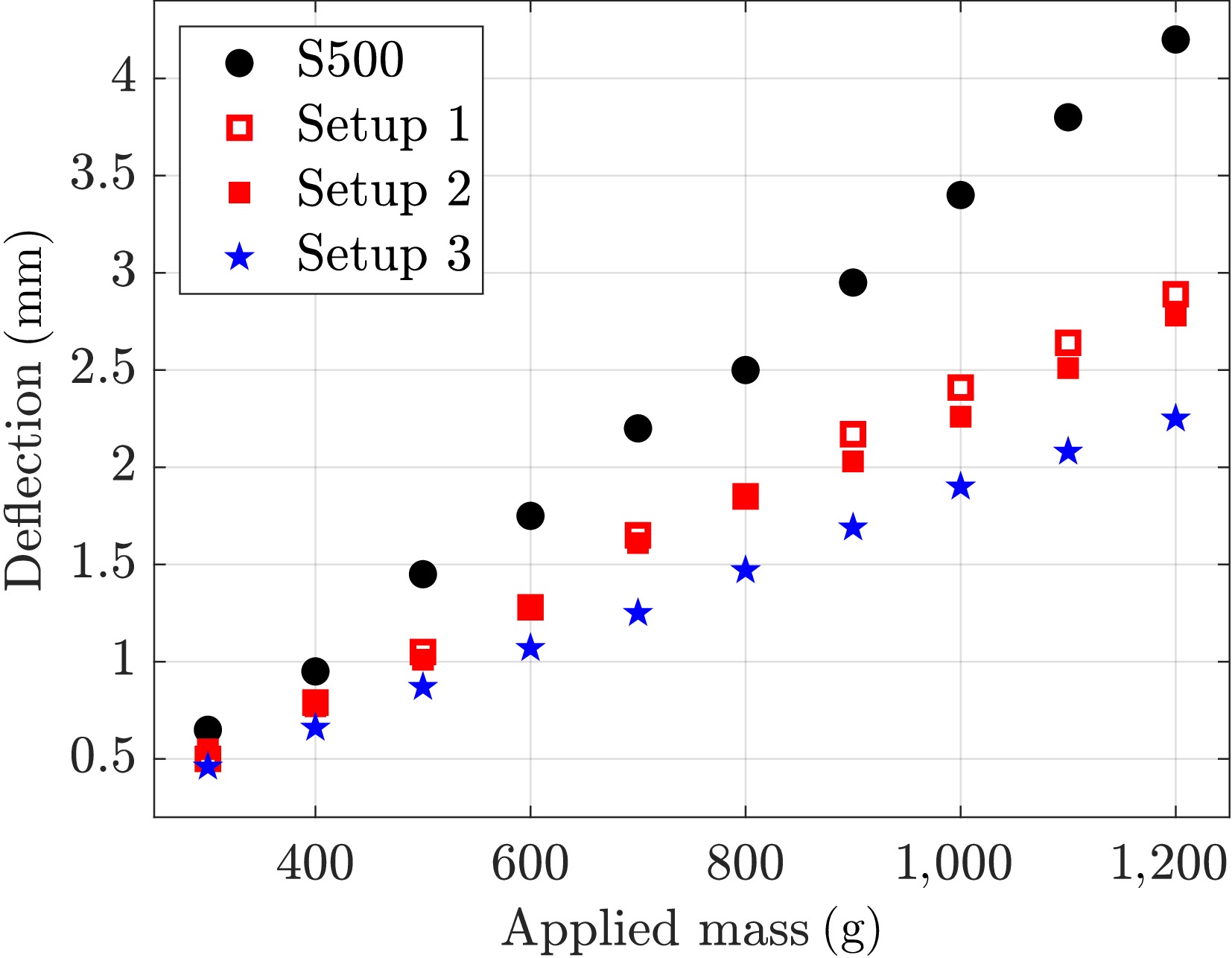
Figure 7.
Summary of load-bearing test results for different rotor arm setups.
To support assembly and modular integration, the RAM_rotorArm geometry incorporates dedicated mounting features for the motor, the RAM_connectorCover, and the RAM_rotorGuard, as shown in Fig. 8. To protect the EPU from accidental contact, the RAM_rotorGuard is designed as a lightweight, sacrificial component. Its dimensions and manufacturing parameters are tailored to minimize additional mass while ensuring sufficient clearance around the propeller. Importantly, the guard is intended to absorb energy in the event of significant impacts, fracturing if necessary to prevent damage to other airframe elements.
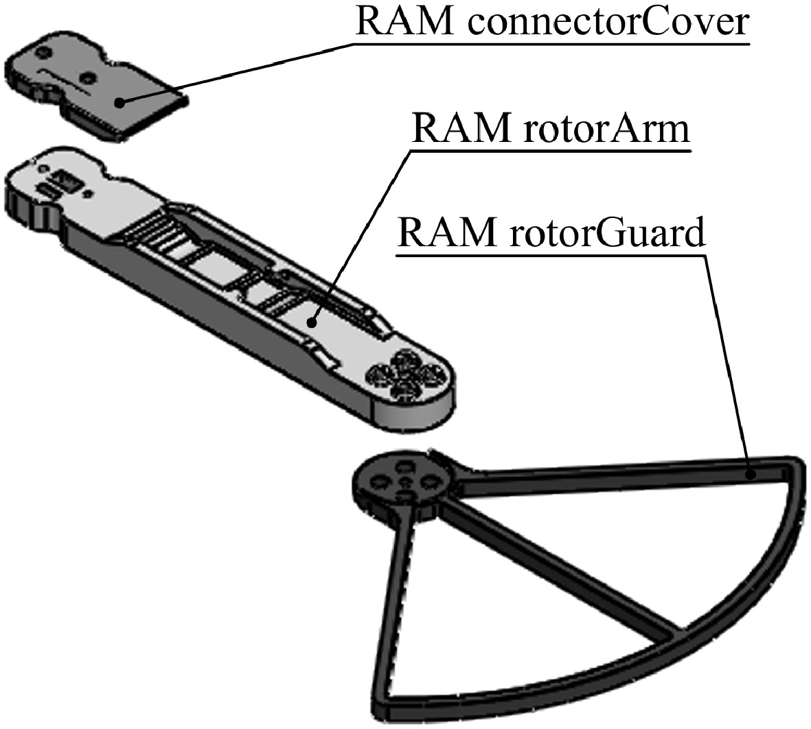
Figure 8.
Exploded view of the parametric RAM airframe.
-
This section presents the manufacturing and assembly of the proposed modular multirotor UAV platform. Additive and subtractive manufacturing technologies are employed to produce the airframe components, which are subsequently assembled into functional UAV modules, demonstrating the practical feasibility of the proposed modular concept. In addition, this section presents a quantitative analysis of mass distribution, hover power consumption, and hovering endurance, providing insight into the influence of manufacturing and design choices on overall system-level performance.
Manufacturing framework overview
-
The manufacturing framework applied in this research follows an integrated digital-to-physical workflow, schematically illustrated in Fig. 9. The process begins with the development of structural and functional parts and assemblies in CAD software, as described in the previous section. Once the CAD models are finalized, they are exported into standardized file formats, such as STL for additive manufacturing and DXF for carbon-fiber sheet cutting, to prepare the components for manufacturing.
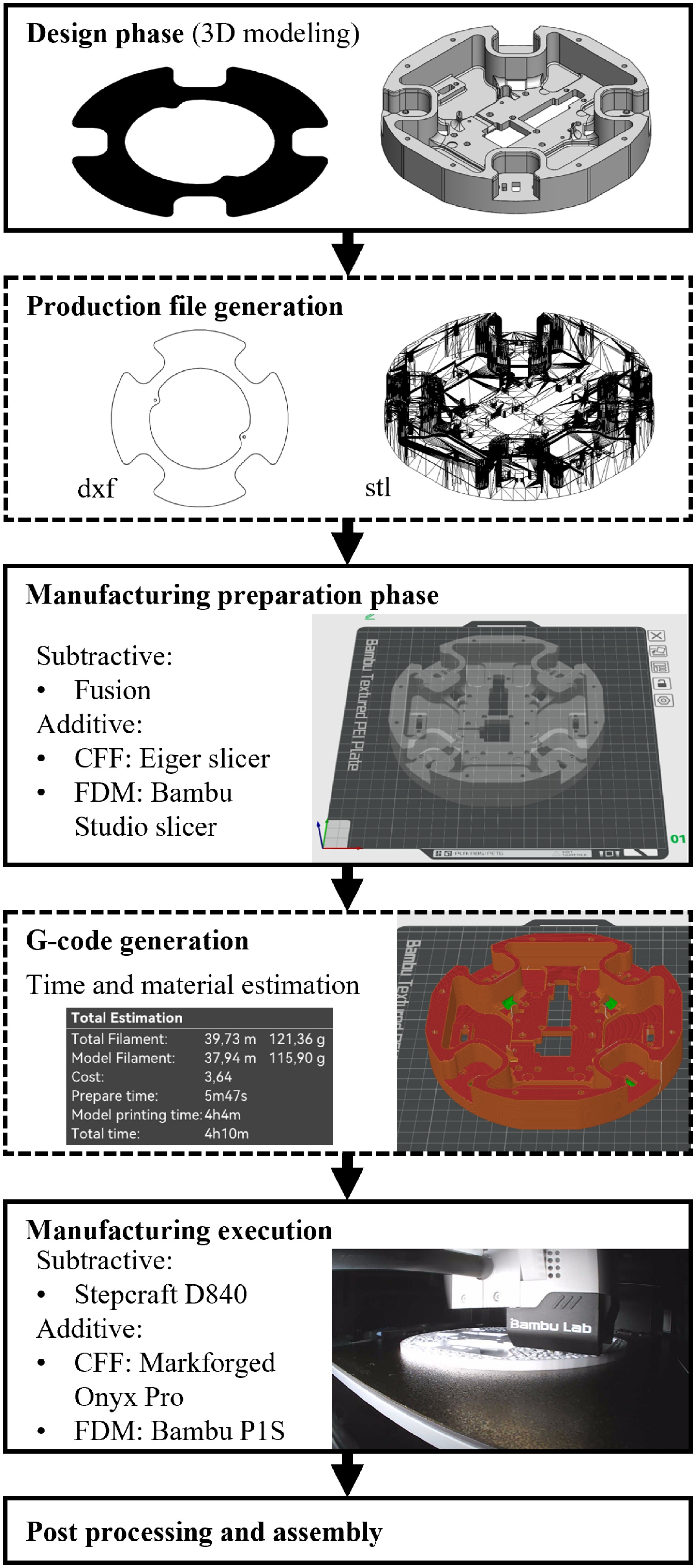
Figure 9.
Overview of the manufacturing framework.
During the manufacturing preparation stage, the exported files are imported into dedicated preprocessing software. For AM, the required printing parameters are defined within a slicer environment, while carbon-fiber sheet cutting involves tool selection and generation of machining programs in a CAM environment. The prepared data are then converted into machine-executable G-code for manufacturing using Bambu Lab FDM and Markforged CFF 3D printers, as well as a Stepcraft M.700 CNC router. Finally, post-processing operations, including support removal and surface finishing, are performed before assembly.
The described manufacturing framework is applied to a case study involving the production of the considered multirotor UAV module configurations. Among the manufactured components, the BM_guideRail, CHM_guideRail, and CHM_lockPlate are produced using carbon-fiber sheet cutting, while all remaining airframe elements are manufactured using AM technologies.
Additive manufacturing of airframe parts
-
AM technologies are employed as the primary production method for the multirotor UAV airframe elements. In this research, FDM is used for the production of the majority of airframe elements, while CFF is selectively applied for the production of the structurally loaded CHM_landingPad part. The CFF process is carried out on a Markforged Onyx Pro system using a carbon-fiber-filled nylon matrix material (Onyx) locally reinforced with continuous fiberglass strands. Manufacturing parameters are defined in the Eiger slicer, using a layer height of 0.1 mm, resulting in a total of 60 layers. Two reinforcement regions are implemented, each consisting of four layers with isotropic fiber orientation, while the matrix parameters follow the recommended default settings (37% infill density, four roof/floor layers, and two wall layers). The production of a single CHM_landingPad part for the mid-size configuration requires 3 h and 27 min, with an estimated material consumption of 18.64 g and a material cost of approximately €6. The measured mass of the manufactured part is 17 g.
All remaining airframe components are produced using FDM technology. Polyethylene Terephthalate Glycol (PETG) material is selected due to its favorable balance of mechanical strength, UV resistance, and thermal stability compared to Polylactic acid (PLA). These properties are particularly important for components exposed to outdoor environmental conditions or positioned near electric motors and power electronics. All FDM parts are printed with a layer height of 0.2 mm, a gyroid infill pattern, and three bottom and five top layers. Variations in the number of wall loops and infill percentage are applied depending on the structural role of each component. Print preparation and slicing are performed using Bambu Studio software.
A case study of the FDM manufacturing process is presented for the third BM_C3 and RAM_C3 configurations. All FDM components are manufactured using a single Bambu Lab P1S 3D printer. Table 3 summarizes the manufactured airframe parts, including the module, configuration, and part identifiers, printing job, estimated part mass, and the number of produced components. Each printing job is characterized by its specific process parameters, including the number of wall loops and the infill percentage. All printing jobs include a preparation time of approximately 6 min.
Table 3. Overview of FDM printing jobs and associated process parameters.
Module Config ID Part name Print job ID Mass (g) Qty BM Default housing_coverXT 1 1.3 1 BM 4S housing_bottomLink 1 9.3 1 BM C3 housing_mainRing 1 9.6 1 BM C3 housing_midRing 1 7.5 1 BM C3 housing_frontRing 1 7.8 1 BM C3 housing bracketFront 1 8.8 1 BM C3 housing bracketRear 1 8.4 1 RAM CW, CCW connectorCover 1 5.2 2 + 2 RAM C3 (CW, CCW) rotorArm 2 36.1 2 + 2 CHM Default landingInterface 2 11.4 2 CHM Default landingLock 2 0.9 2 CHM Default centralHousing 3 115.9 1 CHM Default connectionCover 4 2.1 4 CHM Default brickHousing 4 12.5 1 CHM Default brickXTcover 4 0.9 1 CHM Default, mirror guideSpacer 4 2.6 1 + 1 CHM Default coverFrontRear 4 8.9 1 + 1 CHM Default, USB slot coverSide 4 9.4, 9.2 1 + 1 CHM Default lockPlatePin 4 0.6 2 CHM PX4 Cube carrierFC 4 4.4 1 CHM TBS Nano carrierRC 4 0.7 1 CHM Here 3 carrierGNSS 4 5.1 1 To support efficient production planning, parts manufactured within the same printing job are grouped together, thereby consolidating preparation time, printing time, and material consumption. The printing parameters and associated production effort for the four printing jobs are as follows. Print job 1 uses three wall loops and 20% infill, with a model printing time of 213 min and a total material consumption of 83.9 g. Print job 2 uses four wall loops and 20% infill, with a printing time of 343 min and a total material consumption of 171.5 g. Print job 3, which includes only the CHM_centralHousing part, uses two wall loops and 15% infill, with a printing time of 244 min and a total material consumption of 121.4 g. Print job 4 also uses two wall loops and 15% infill, with a printing time of 176 min and a total material consumption of 73.4 g.
To enable a comprehensive analysis and discussion, the mass distribution for all considered BM and RAM configurations is investigated. Comparative mass distributions for the BM (
$ {m}_{\text{BM}} $ $ {m}_{\text{RAM}} $ $ {m}_{\text{bat}} $ $ {m}_{\text{BM}\_\text{af}} $ $ {m}_{\text{BM}\_\text{gR}} $ $ {m}_{\text{BM}\_\text{hp}} $ $ {m}_{\text{BM}\_\text{fh}} $ $ {m}_{\text{EPU}} $ $ {m}_{\text{RAM}\_\text{rA}} $ $ ({m}_{\text{RAM}\_\text{rC}}) $ $ {m}_{\text{RAM}\_\text{fh}} $ $ {m}_{\text{RAM}\_\text{rG}} $ 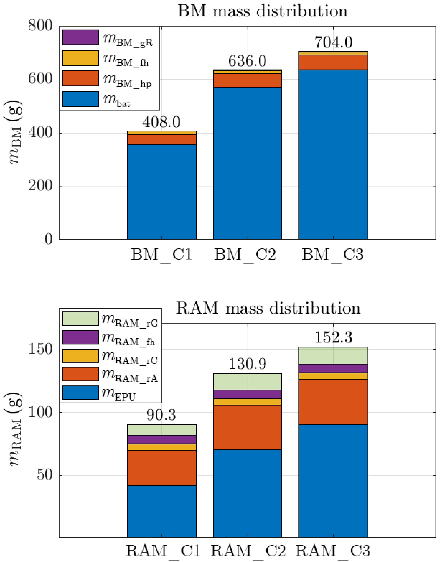
Figure 10.
Comparison of mass distribution for the proposed BM and RAM configurations.
The mass of the central housing module (
$ {m}_{\text{CHM}} $ Assembly of functional multirotor UAV modules
-
The assembly of the multirotor UAV modules was performed following the completion of manufacturing, integrating electronic components, structural parts, and fastening hardware into functional subsystems. Assembly of the CHM involved the integration of onboard electronics with the manufactured airframe components. The CHM provides the core avionics required for outdoor multirotor operation, including a Cube-series FC, a ProfiCNC/HEX Here 3 GNSS module, and a Team BlackSheep Crossfire Nano RX for remote control. Following mechanical and electrical integration, the fully assembled CHM was calibrated to ensure reliable operation, as shown in Fig. 11.
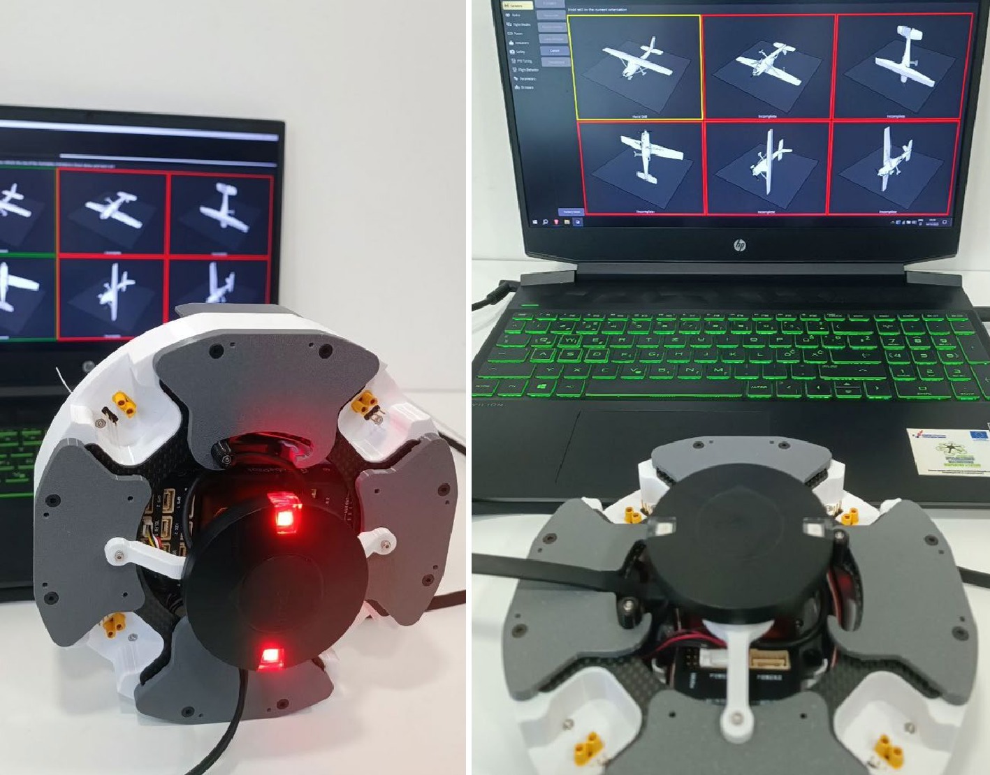
Figure 11.
Assembled CHM airframe with integrated avionics during inertial sensor calibration.
Assembly of the BMs began with the replacement of the original battery connectors with XT60 connectors. Sequential mechanical assembly then included positioning the mainRing, midRing, and frontRing around the battery, followed by fastening the guideRail, bottomLink, coverXT, bracketFront, and bracketRear parts. Assembly of the RAMs began with EPU preparation, including soldering the BLDC motor phase wires to the ESCs and soldering XT30 connectors. This was followed by integration into the 3D-printed airframe parts, including installation of the fastening hardware. Each assembled RAM was subsequently tested to verify rotation direction.
A comparative overview of the assembled multirotor platform configurations is presented in Fig. 12, illustrating two key performance indicators: total system mass and estimated hover power consumption. The comparison highlights the influence of different BM and RAM configurations on the mass–power relationship, enabling a direct assessment of configuration efficiency at the system level. The combined representation of system mass and hover power consumption provides quantitative insight into the mass–power trade-off, which is a critical factor affecting thrust-to-weight ratio, endurance, and payload capability. The estimated hover power is obtained from the experimentally identified propulsion model presented in Section II and serves as the basis for preliminary estimation of hovering endurance. Under hovering conditions, the thrust generated by each rotor is assumed to be identical and is given by
$ {f}_{\text{R},\text{hov}}={m}_{\text{TO}}g/N, $ where
$ {m}_{\text{TO}}={m}_{\text{CHM}}+N{m}_{\text{RAM}}+{m}_{\text{BM}} $ $ {P}_{\text{hov}}=N{P}_{\text{R}}({f}_{\text{R},\text{hov}}), $ where
$ {P}_{\text{R}}(\cdot ) $ $ {t}_{\text{hov},\text{est}}=60{C}_{\text{bat}}S{U}_{\text{nom}}/{P}_{\text{hov}}, $ where
$ {C}_{\text{bat}} $ $ S $ $ {U}_{\text{nom}} $ 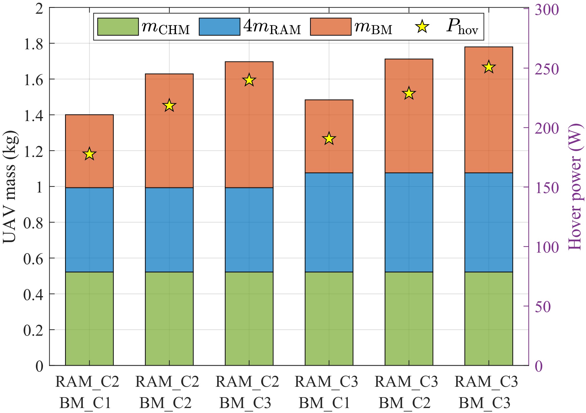
Figure 12.
Comparative overview of the six configurations, showing the total mass and the estimated hover power consumption.
-
The tested multirotor UAV platform is presented in Fig. 13, showing the fully assembled platform, hovering flight, and the flight plan used for experimental evaluation. The Cube series FCs support QGroundControl (QGC), Mission Planner (MP), and MATLAB Simulink, enabling autonomous mission execution and post-flight analysis. Before the flight experiments, the FC, propulsion system, and onboard sensors were configured and calibrated using standard QGC procedures.
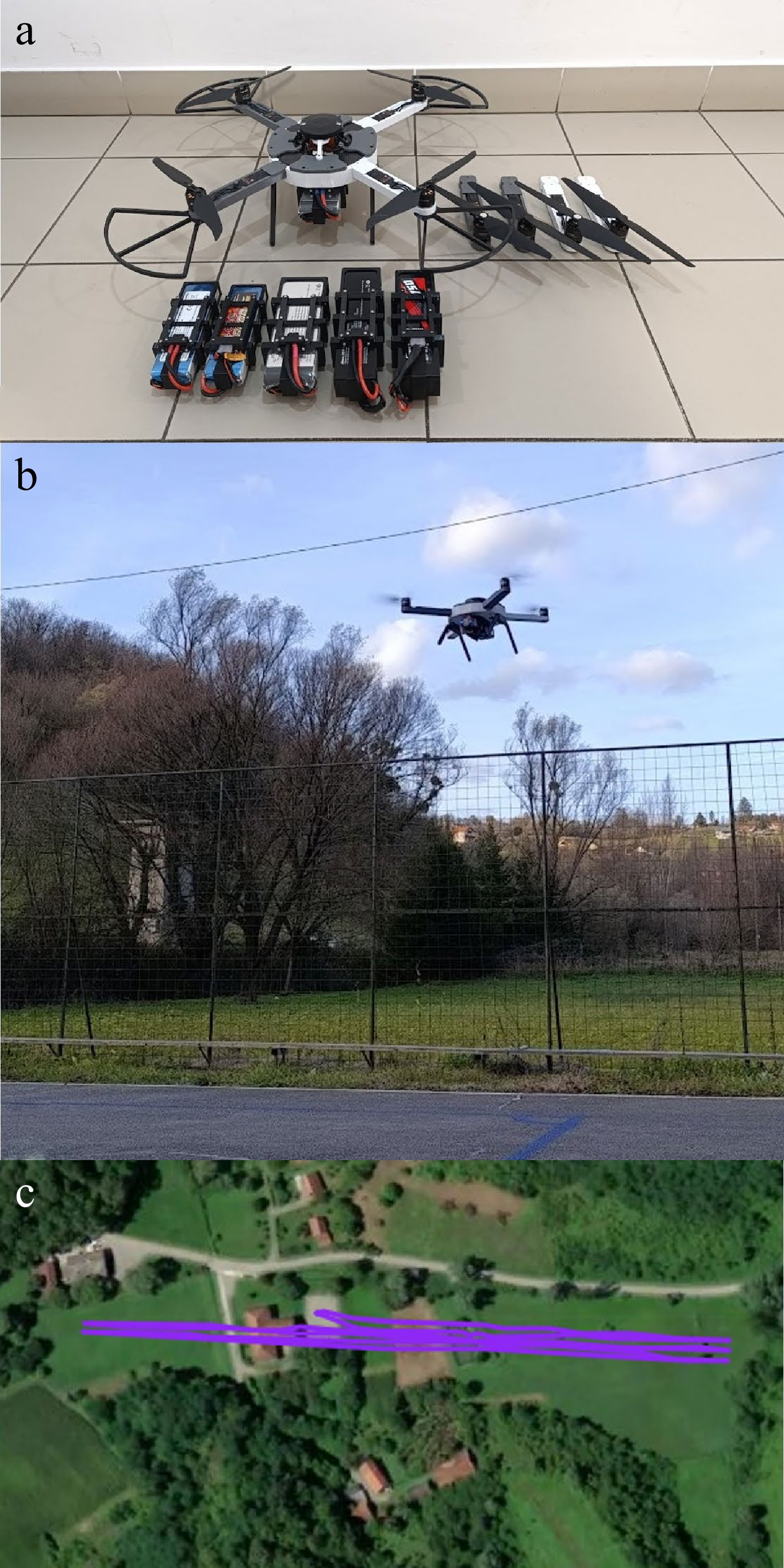
Figure 13.
Tested multirotor UAV platform: (a) fully assembled platform with all modules ready for testing, (b) platform in hovering flight, and (c) flight plan used for the forward-flight experiments.
Prior to the flight scenarios, each platform underwent automated gain-tuning to ensure stable operation. This procedure was repeated for each tested configuration, and all flight tests were conducted without rotorGuard parts or without additional payloads. The experimental setup included onboard avionics and the RadioMaster TX16S transmitter for remote control. All flight data were continuously logged by the FC. The campaign was structured into three case studies to evaluate UAV performance across key flight regimes: (1) hovering flight, (2) steady horizontal flight, and (3) pattern-based autonomous flight.
The first case study evaluated hovering stability and endurance for six quadrotor configurations, combining two RAM and three BM configurations. The hover test procedure was identical for all configurations: automated take-off to a fixed altitude, followed by steady hovering until the battery voltage reached the 3.3 V per cell cutoff threshold. Flights were conducted under nearly windless conditions, while onboard logging continuously recorded voltage data. Using the formulation proposed in Section IV, the estimated hovering endurance was 18.74, 30.48, and 24.99 min for the RAM_C2 configurations combined with BM_C1, BM_C2, and BM_C3, respectively, and 17.47, 29.12, and 23.90 min for the corresponding RAM_C3 configurations. The experimentally measured voltage profiles over time are presented in Fig. 14.
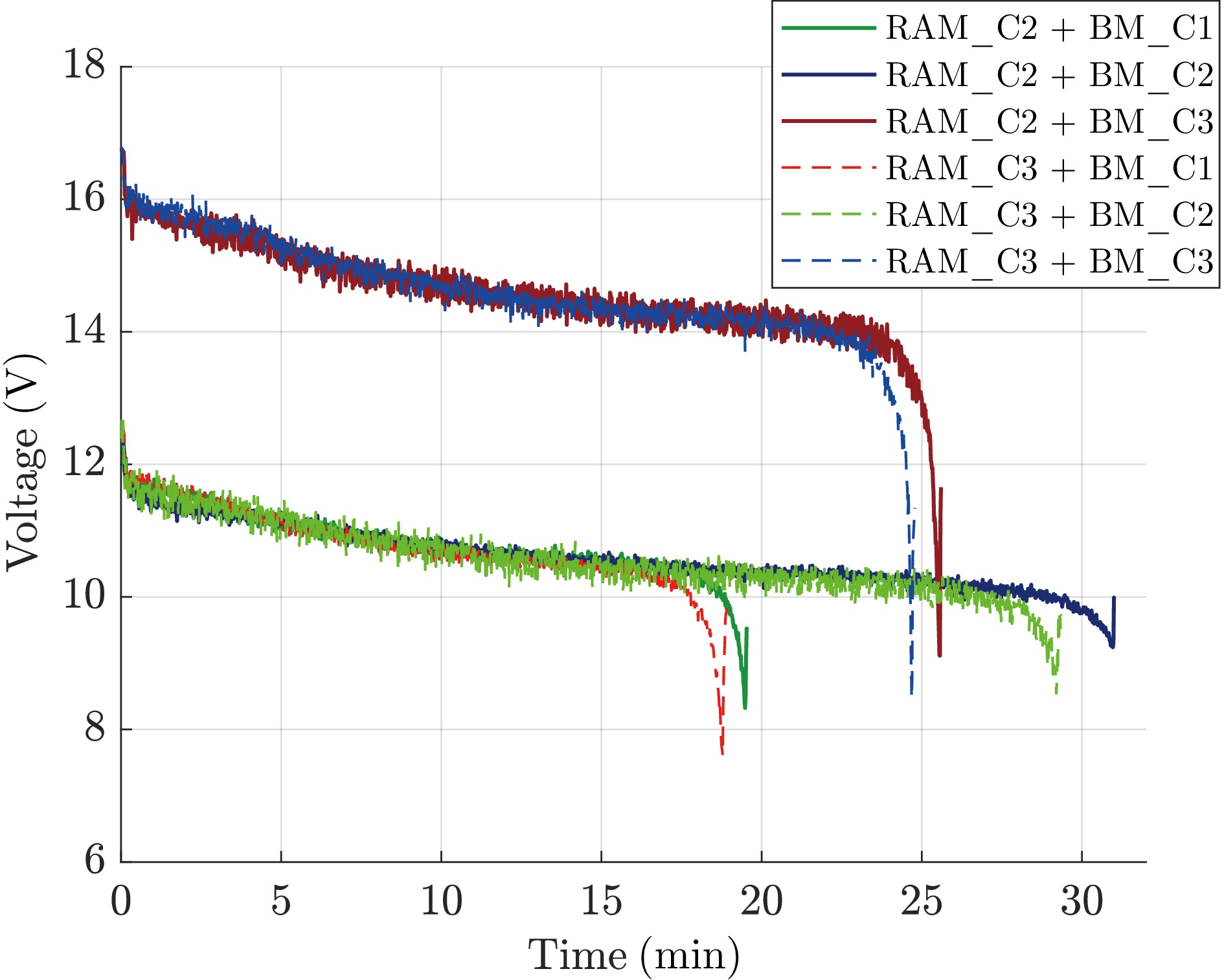
Figure 14.
Voltage profiles over time during hovering for six multirotor UAV configurations, illustrating discharge characteristics and total hovering duration.
A close agreement between the estimated and experimentally measured hovering endurance can be observed for all six configurations. The obtained results confirm that the experimentally identified propulsion model, combined with the proposed sizing methodology, provides a practical analytical tool for preliminary hovering endurance estimation during the conceptual UAV design stage. Minor deviations are primarily attributed to factors not explicitly included in the simplified analytical formulation, such as battery characteristics under load, environmental conditions, and controller activity during flight. Although no direct experimental comparison with external platforms was conducted, the obtained mass–power relationship and hovering endurance provide a quantitative basis for benchmarking against representative commercial multirotor UAV platforms, such as the S500-based quadrotor configuration. The proposed modular platform achieves a favorable balance between structural efficiency and functional flexibility while maintaining competitive hover performance.
The second case study evaluated the dynamic performance of the proposed platform during forward flights. The flight trajectory, shown in Fig. 13c, consisted of repeated straight-line segments connected by 180° turns, covering a total distance of approximately 1.7 km while maintaining an altitude of approximately 30 m. This case study provided a consistent basis for evaluating flight stability, aerodynamic loading, and propulsion performance, and will serve as the basis for future experimental identification of aerodynamic drag forces and moments.
Each configuration was evaluated at three predefined horizontal velocities: 8, 10, and 12 m/s, set within QGC mission planning. Tests were conducted under moderately strong wind conditions to assess platform performance in realistic operational environments. Representative time-domain responses for the RAM_C2 + BM_C3 configuration are presented in Fig. 15. The first two subplots present three-axis angular rates and corresponding estimated angles, followed by the translational velocity, position, and estimated electrical power. The electrical power was estimated from the onboard battery voltage and current measurements using an empirically identified current scaling factor obtained from the hovering experiments. Together, these responses provide quantitative insight into the dynamic behavior, flight stability, and propulsion demand during horizontal flight.
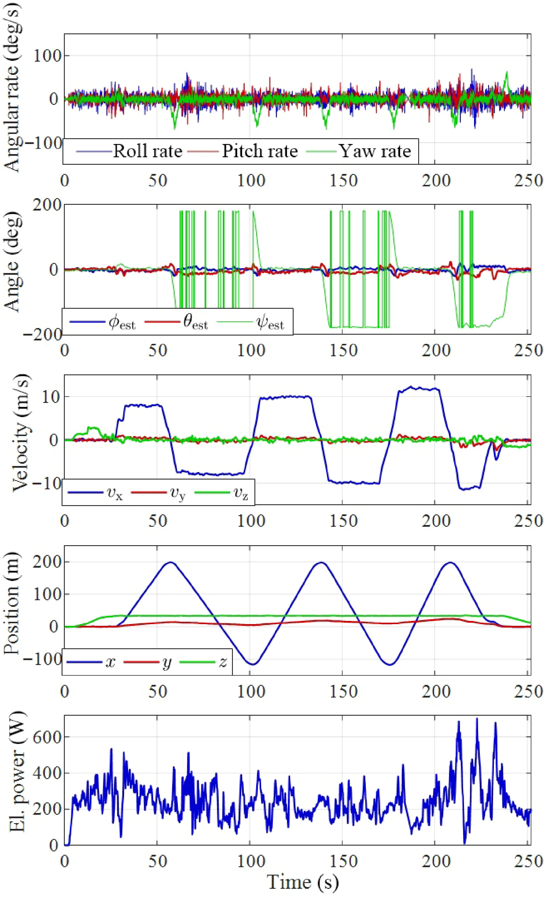
Figure 15.
Flight data for the RAM_C2 + BM_C3 configuration, including angular rates, estimated Euler angles, translational velocity, position, and electrical power, all shown as functions of time.
The third case study assessed autonomous navigation and path-following capability using a predefined three-dimensional waypoint mission with continuous position logging. Overall, the novel modular multirotor platform was successfully tested across all primary operational flight regimes. No flight anomalies, control instabilities, or hardware faults were observed, confirming reliable system performance. The results demonstrate the feasibility and flexibility of the proposed modular design while highlighting the influence of different BM and RAM configurations on system-level performance.
-
This paper presented the design, manufacturing, and experimental validation of a novel modular and scalable multirotor UAV platform. The airframe architecture introduces a plug-and-play concept based on three independently designed modules, BM, RAM, and CHM, enabling rapid reconfiguration, simplified maintenance, and adaptation to different propulsion and energy setups. The parametric design methodology, combined with additive and subtractive manufacturing, demonstrated that structurally reliable UAV components can be produced rapidly while maintaining high customizability. Mechanical characterization, along with analysis of mass distribution and hovering power, confirmed the suitability of the selected materials and highlighted the influence of modular design on system-level performance.
The complete platform was evaluated across multiple UAV configurations through three flight scenarios: hovering, steady horizontal flight, and autonomous waypoint-based navigation. All configurations exhibited stable operation without anomalies, providing strong experimental validation of the airframe concept and its modular assembly principles. Compared to conventional fixed-architecture multirotor UAV platforms, the proposed system offers enhanced adaptability through modular reconfiguration while maintaining competitive mass–power characteristics, thereby enabling more efficient adaptation to varying mission requirements. Rather than targeting a single application, the proposed platform is conceived as a flexible research and development UAV architecture that supports rapid evaluation of different propulsion systems, battery configurations, onboard sensing solutions, and mission-specific payloads within a common modular framework. Overall, the results demonstrate that the proposed architecture offers a robust foundation for adaptable, mission-flexible UAV systems. Future work will focus on extending the modularity to larger-scale variants with increased payload capacity and on further integration of advanced functionalities. A supplementary video demonstrating the platform design, modular reconfiguration, and representative flight scenarios is available online at:
www.youtube.com/watch?v=pP3tzFDh3NQ . -
Not applicable.
-
The authors confirm contributions to the paper as follows: study conception and design: Kotarski D, Šćuric A, Petrović T; data collection: Kotarski D, Šćuric A; analysis and interpretation of results: Kotarski D, Šćuric A, Petrović T; draft manuscript preparation: Kotarski D. All authors reviewed the results and approved the final version of the manuscript.
-
The datasets generated during and/or analyzed during the current study are available from the corresponding author upon reasonable request.
-
The authors declare that they have no conflict of interest.
- Copyright: © 2026 by the author(s). Published by Maximum Academic Press, Fayetteville, GA. This article is an open access article distributed under Creative Commons Attribution License (CC BY 4.0), visit https://creativecommons.org/licenses/by/4.0/.
-
About this article
Cite this article
Kotarski D, Šćuric A, Petrović T. 2026. Design, manufacture, and performance evaluation of a novel modular multirotor UAV platform. International Journal of Micro Air Vehicles 18: e024 doi: 10.48130/mav-0026-0024 

Design, manufacture, and performance evaluation of a novel modular multirotor UAV platform
- Received: 27 March 2026
- Revised: 05 July 2026
- Accepted: 03 August 2026
- Published online: 02 November 2026
Abstract: This paper presents the design, manufacture, and experimental validation of a novel modular and scalable multirotor Unmanned Aerial Vehicle (UAV) platform featuring rapid plug-and-play reconfigurability. The airframe architecture is built upon three functional modules: rotor arms, a battery module, and a central hub module, integrated through mechanical and electrical connections that support rapid assembly, reconfiguration, and flexible adaptation to mission-specific requirements. A complete manufacturing workflow is implemented using a combination of additive and subtractive technologies, followed by assembly into functional UAV modules. Quantitative analyses of mass distribution and energy consumption during hovering are conducted to evaluate system-level design implications. The developed platforms are experimentally tested across three flight scenarios, and results demonstrate stable operation across all tested configurations without flight anomalies or control instabilities, confirming the reliability and effectiveness of the proposed modular airframe concept. The presented work provides a validated foundation for adaptable and reconfigurable multirotor UAV systems, enabling efficient adaptation to diverse operational requirements.