-
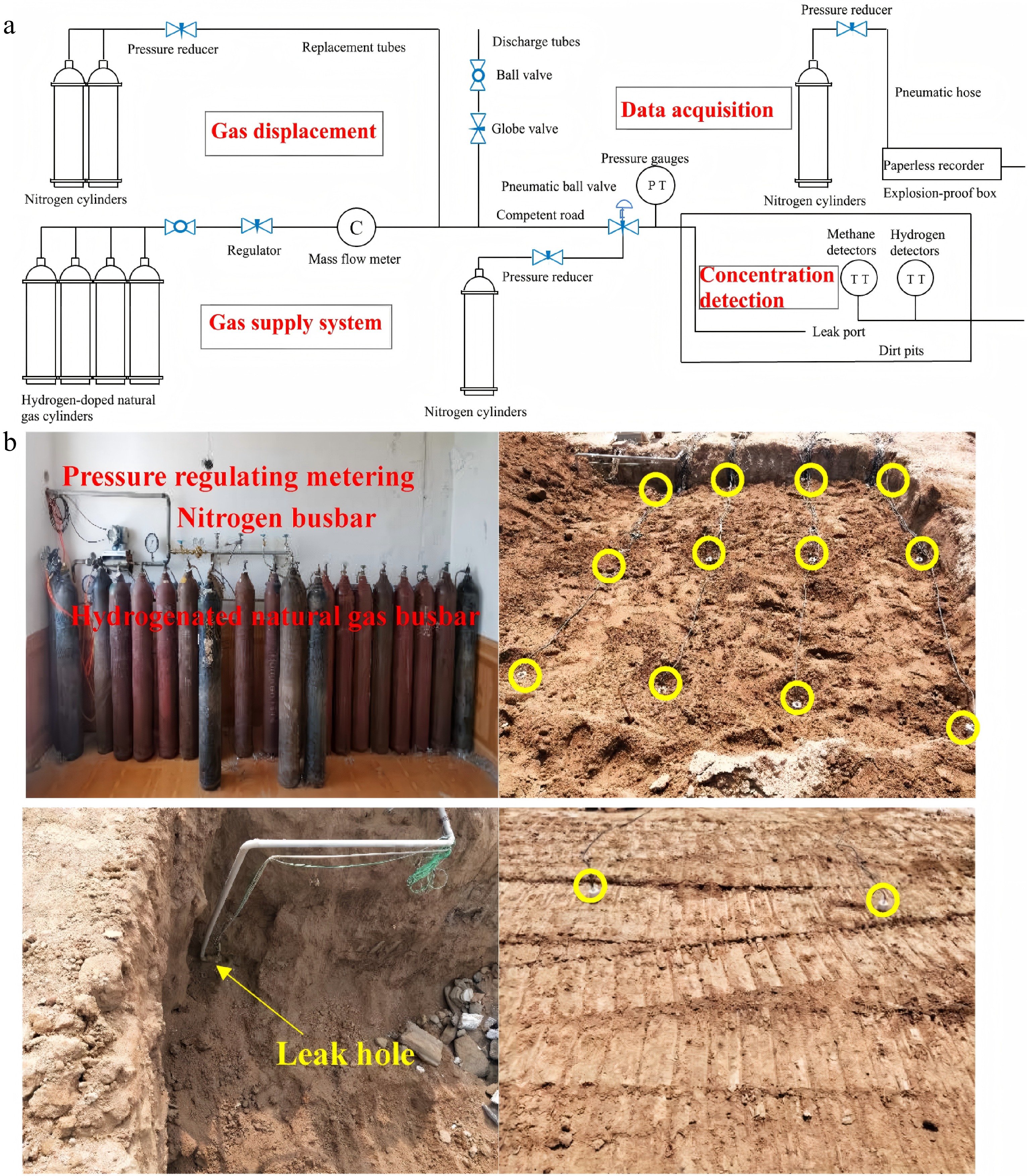
Figure 1.
(a) Leakage test system of H2-doped CH4 underground pipeline. (b) Diagram of the experiment site[18].
-
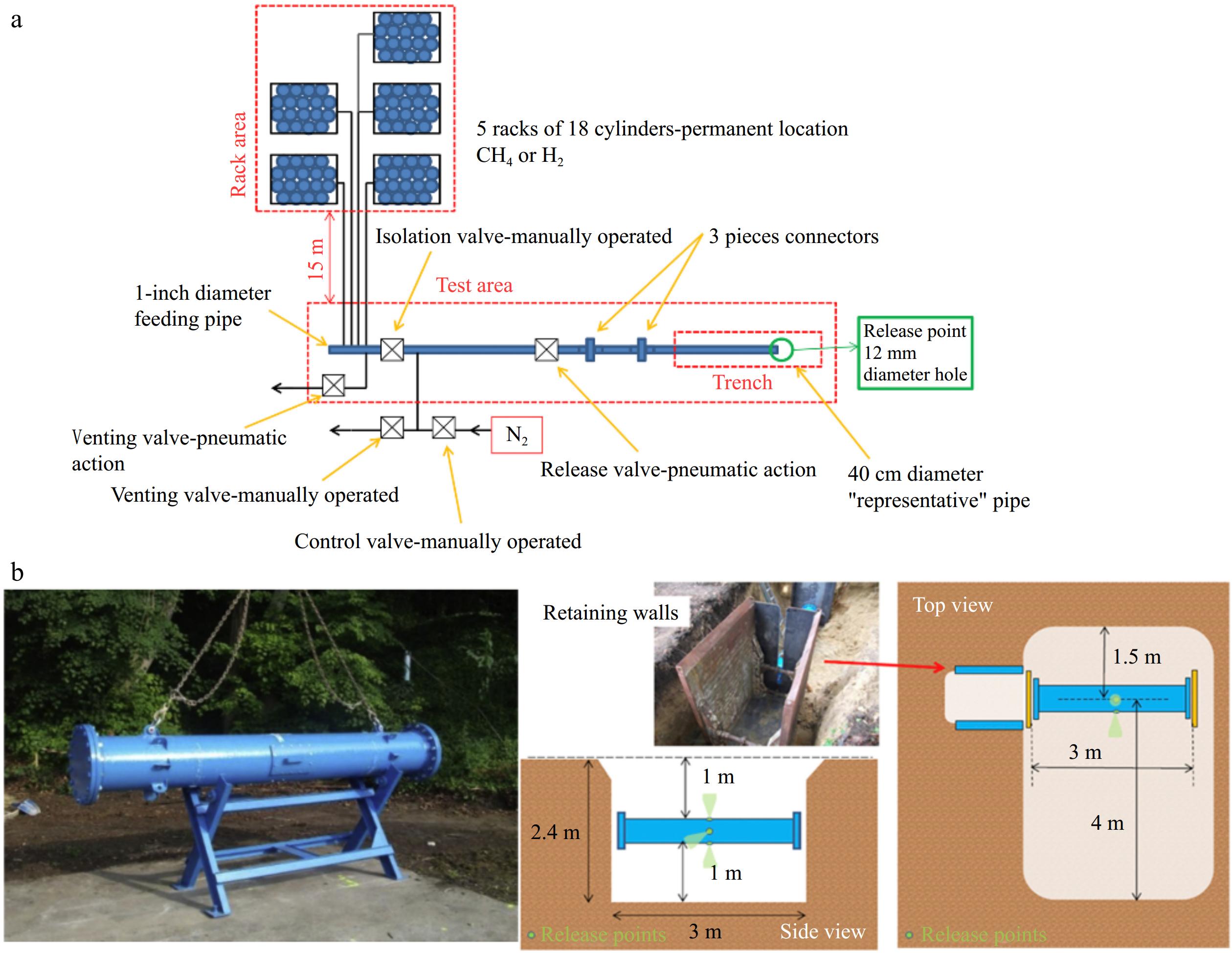
Figure 2.
(a) Schematic layout of leakage simulation test facility. (b) The 40 cm diameter test pipe and the position of the pipe in the trench[19].
-
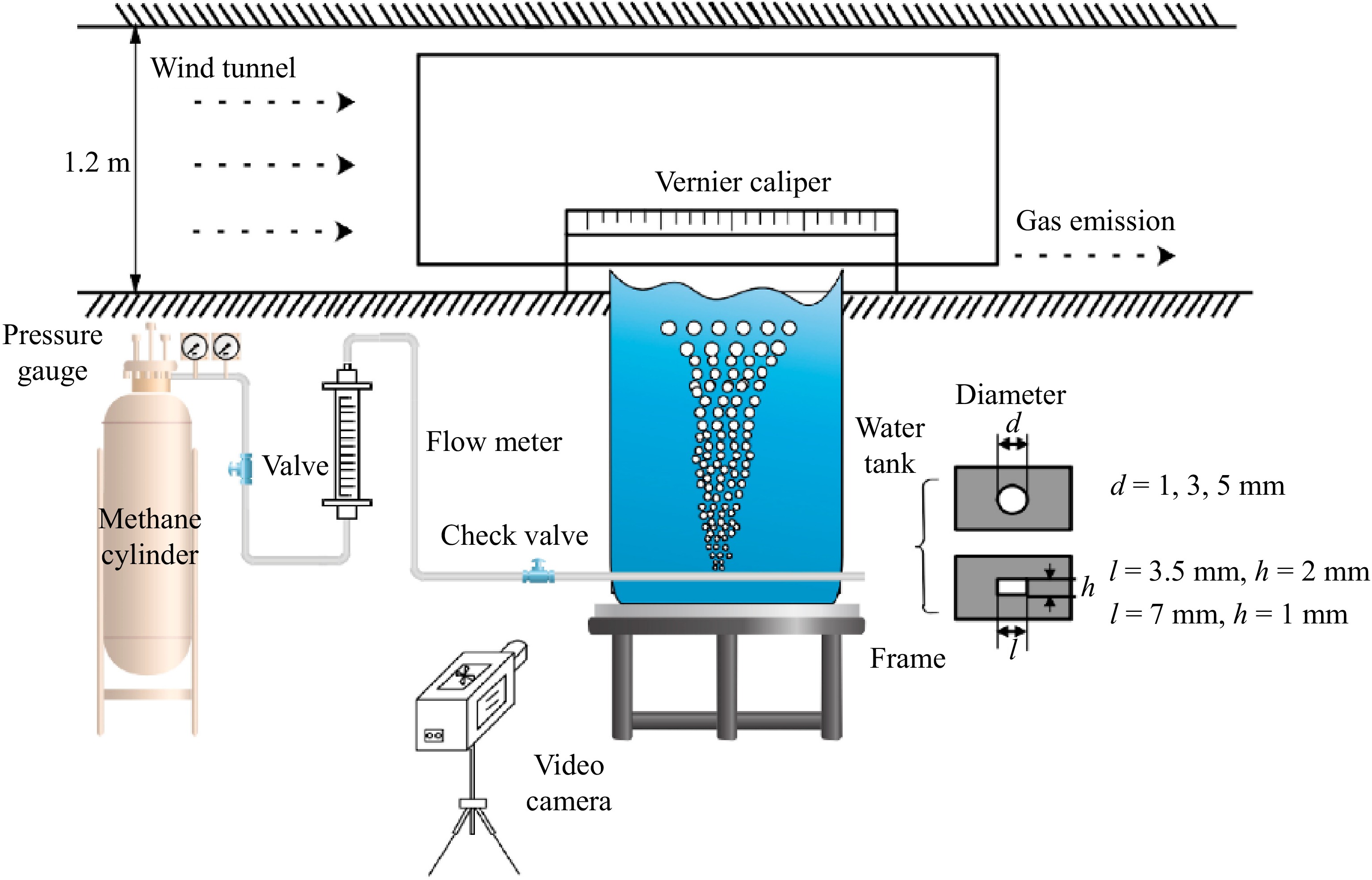
Figure 3.
Schematic diagram of experimental device[36].
-
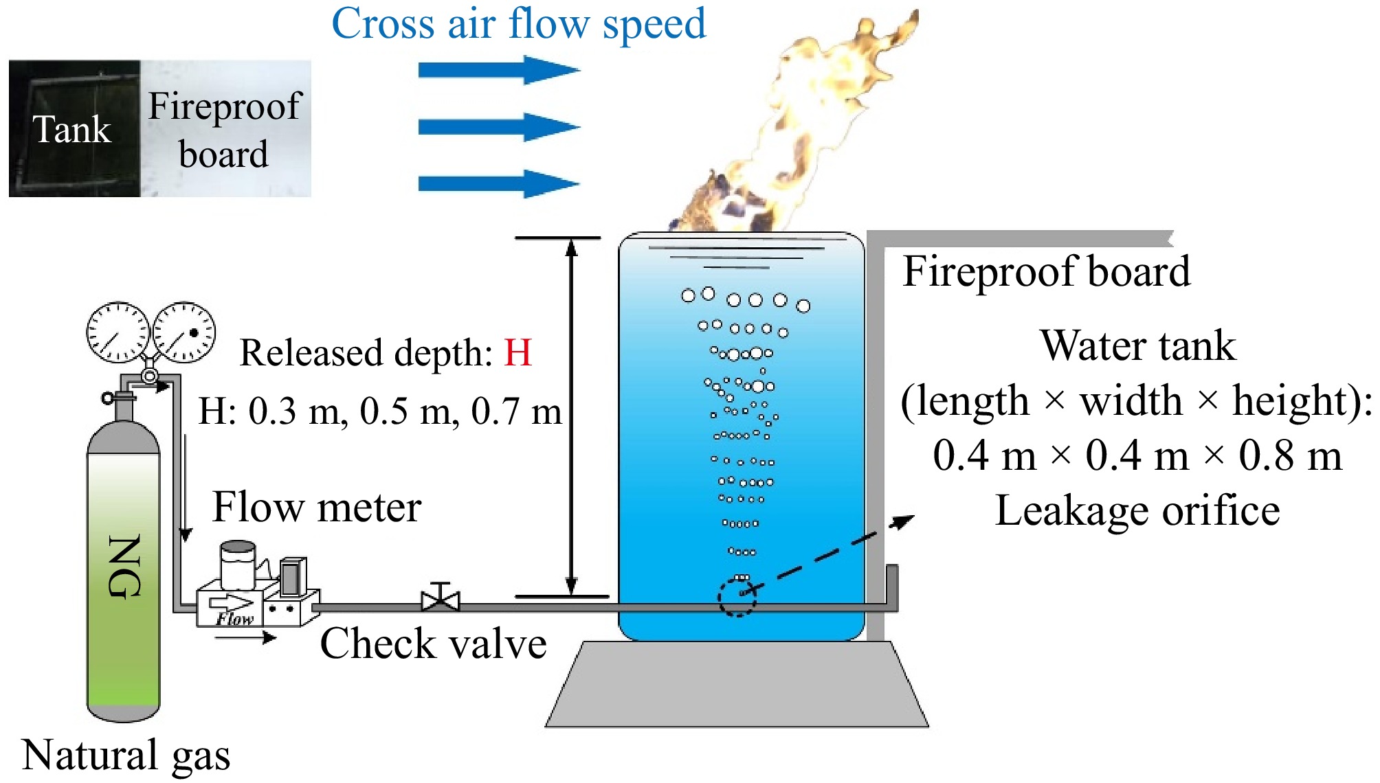
Figure 4.
Schematic diagram of experimental setup[37].
-
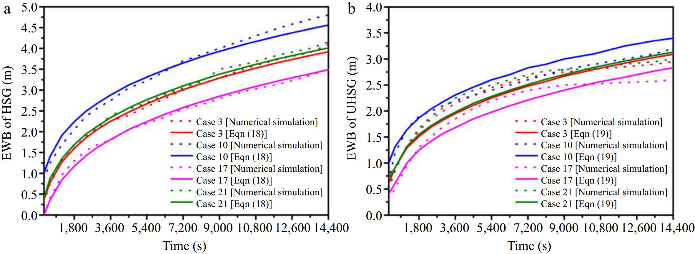
Figure 5.
(a) Verification of the EWB calculation model under HSG conditions. (b) Verification of the EWB calculation model under UHSG conditions[17].
-
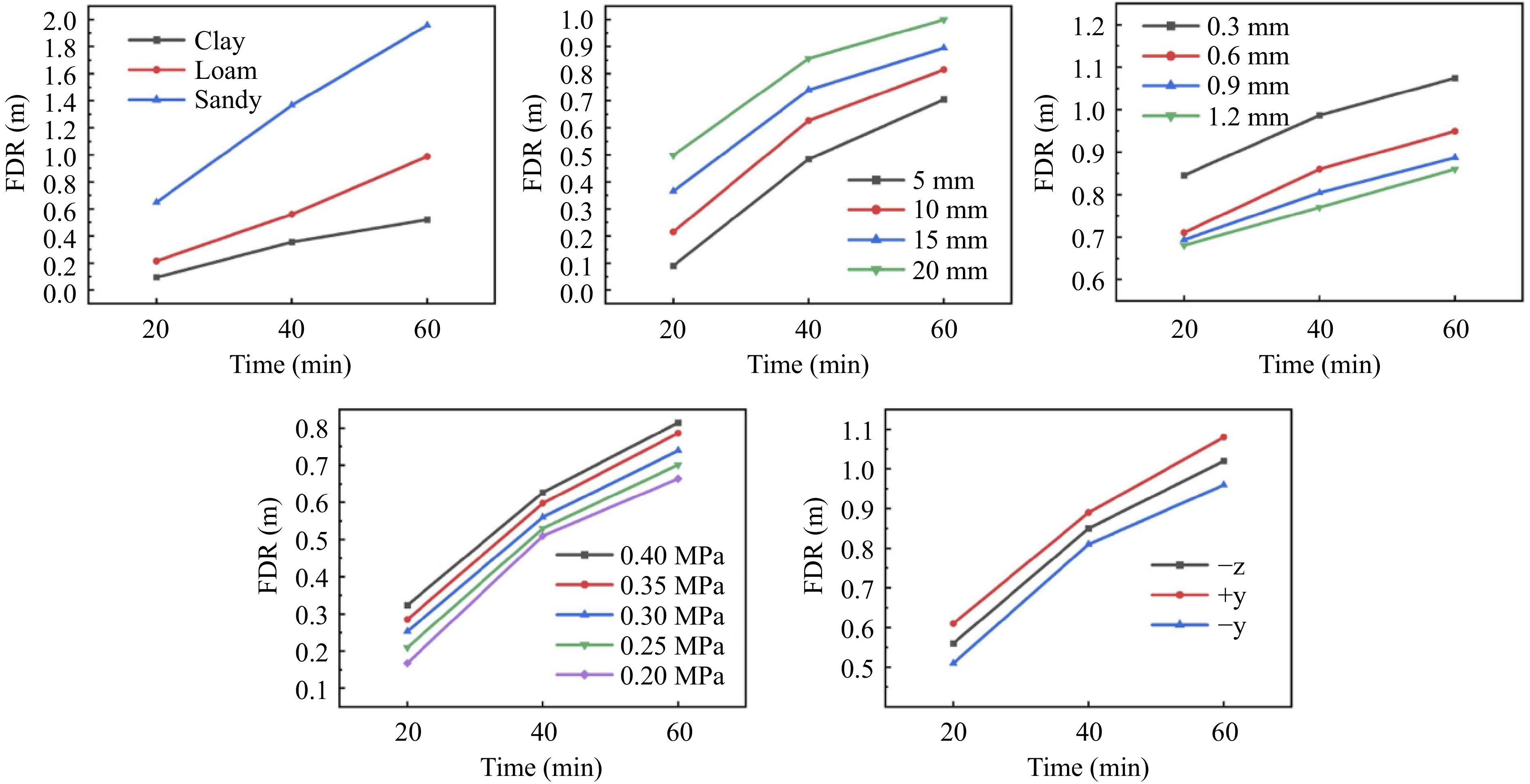
Figure 6.
FDR varies with different parameters[41].
-
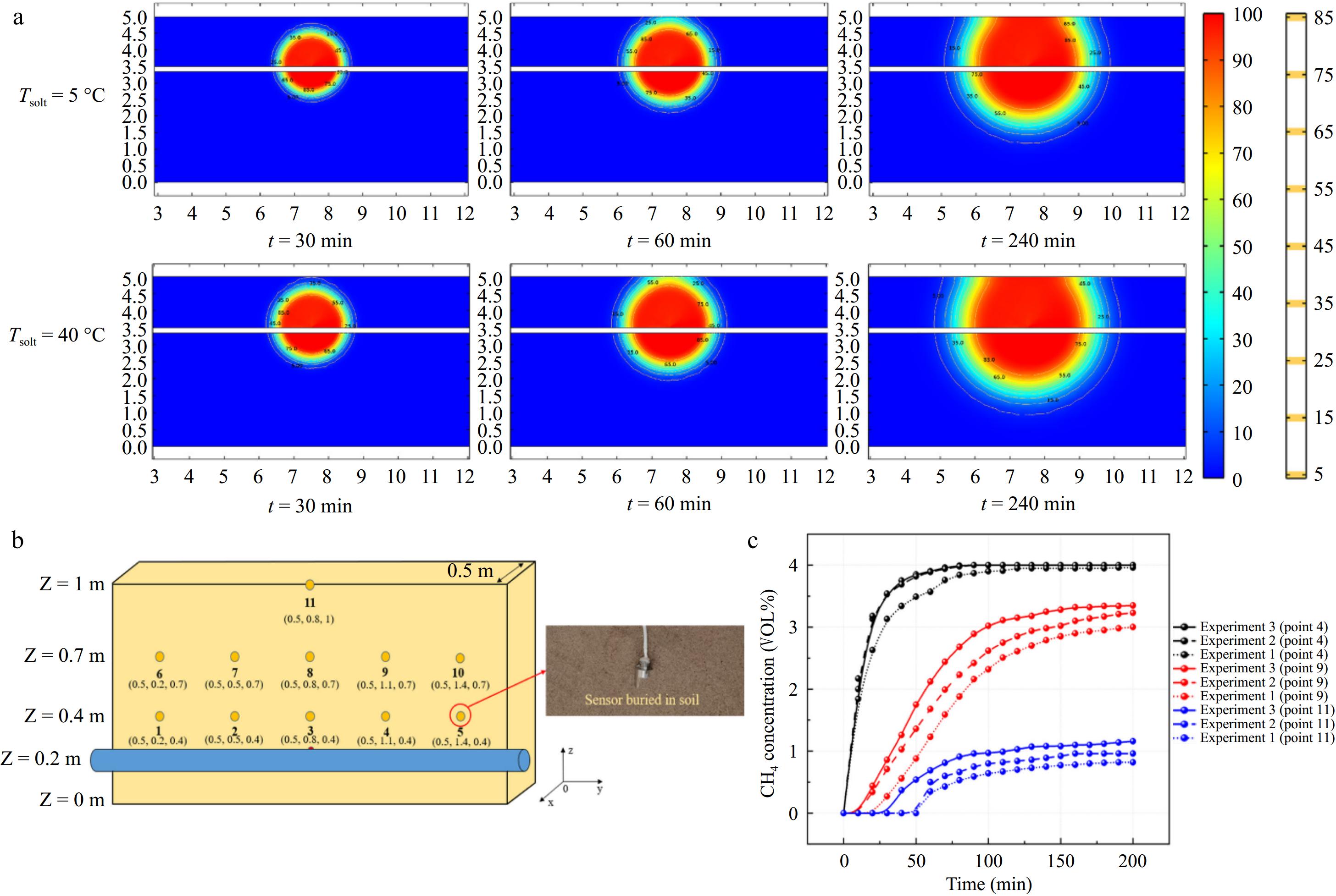
Figure 7.
(a) Contour of methane concentration changes with time at different soil temperatures obtained from simulations. (b) Layout and number of sensors. (c) Comparison of concentrations at different temperatures from experiments (Experiment 1: T = 5 °C, Experiment 2: T = 15 °C, Experiment 3: T = 25 °C)[20].
-
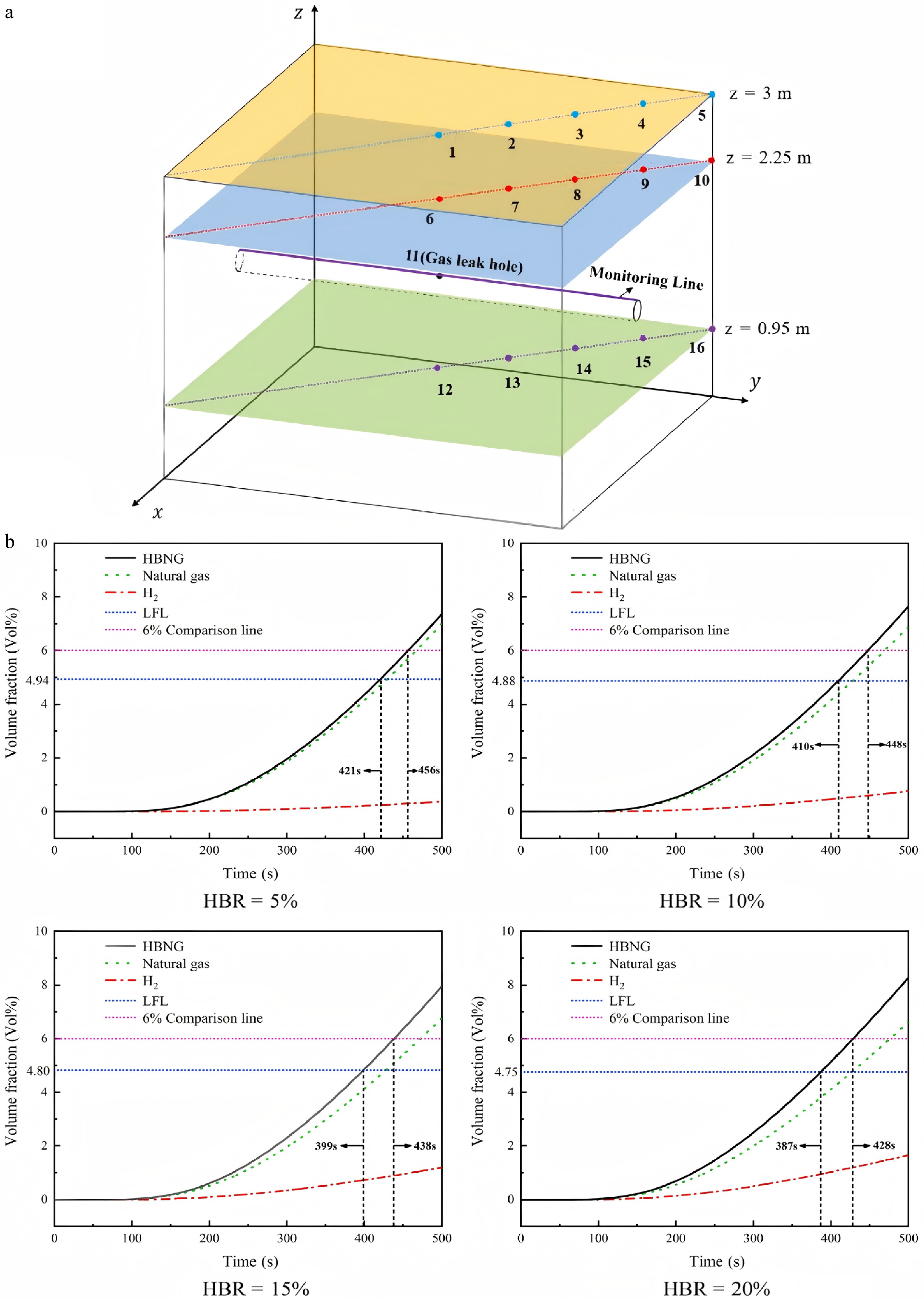
Figure 8.
(a) Layout of leakage ports and monitoring points. (b) Changes in the concentration of H2-doped CH4 at monitoring point 2 within 500 s[51].
-
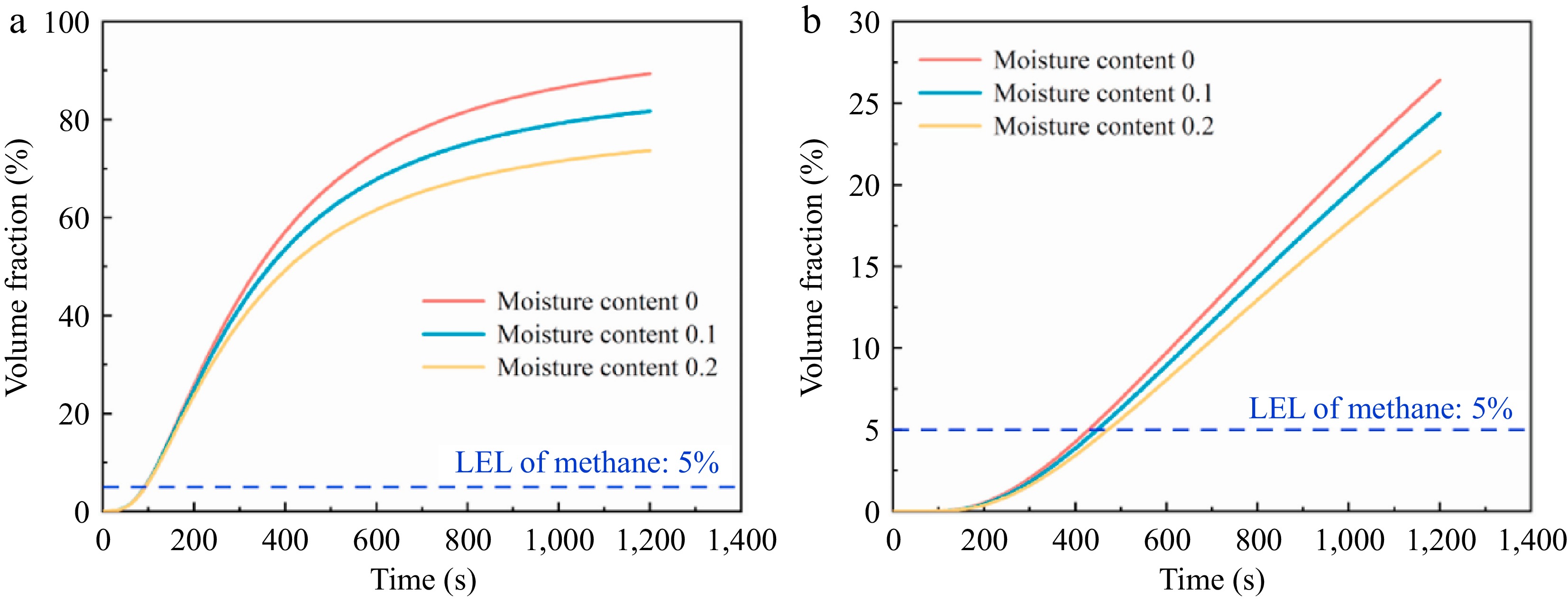
Figure 9.
Effect of soil moisture content on gas volume fraction. (a) and (b) present data from different monitoring points[52].
-
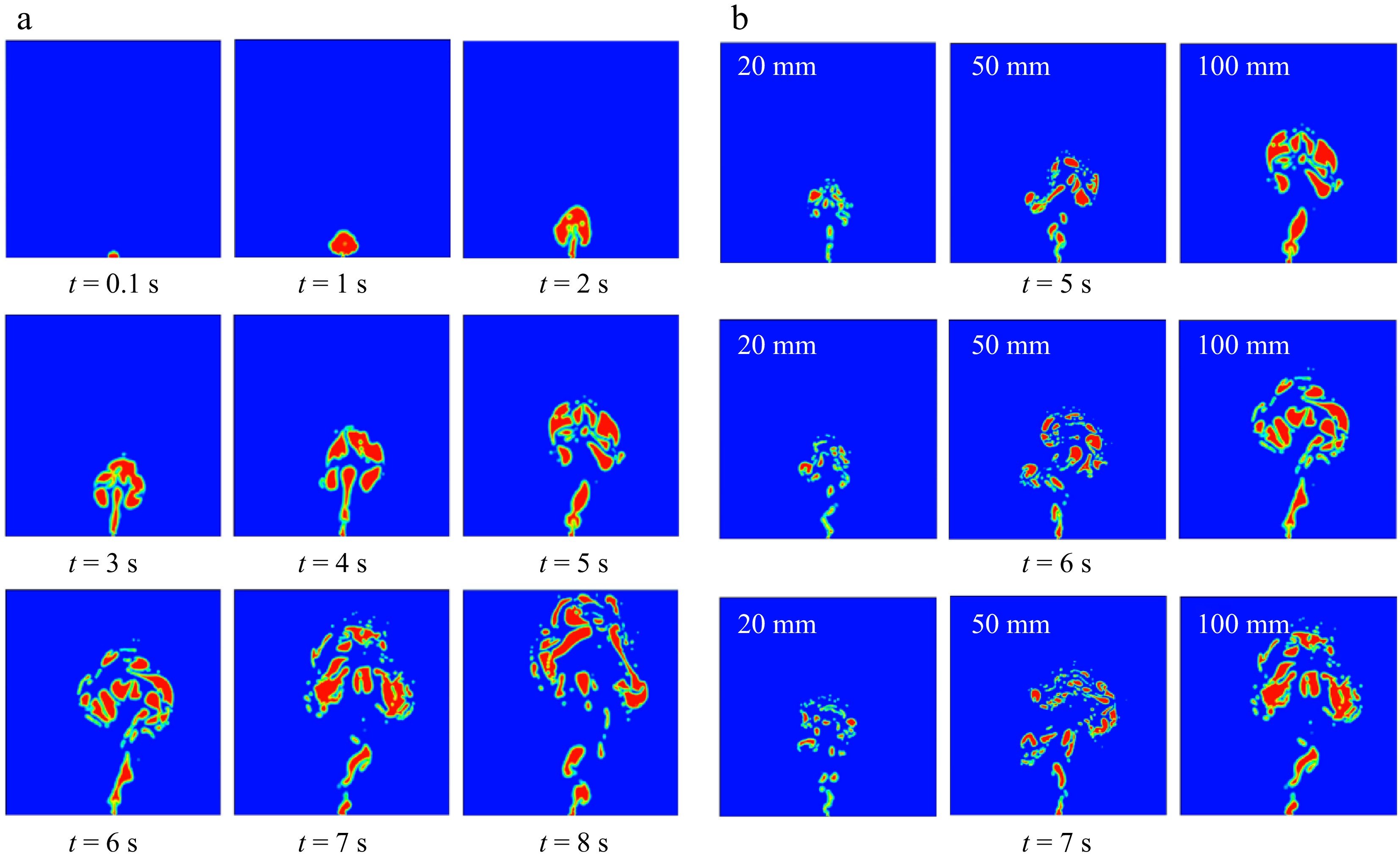
Figure 10.
(a) Gas leakage and diffusion from a submarine pipeline over time. (b) Gas leakage and diffusion over time for leak apertures of 20, 50, and 100 mm, respectively[59].
-
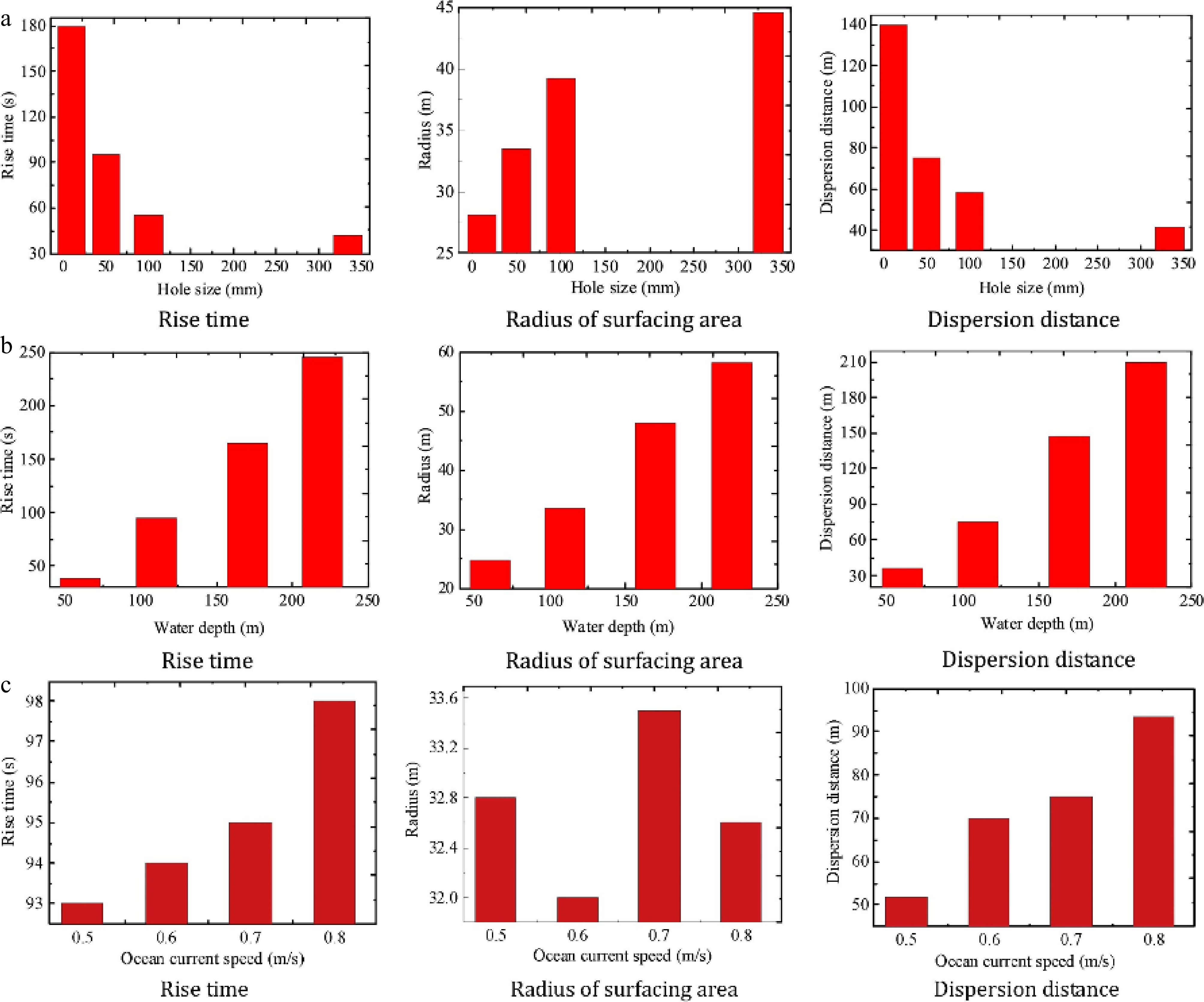
Figure 11.
(a) Comparison of gas diffusion parameters at different leakage depths. (b) Comparison of gas diffusion parameters at different ocean velocities. (c) Comparison of gas diffusion parameters at different release rates[62].
-
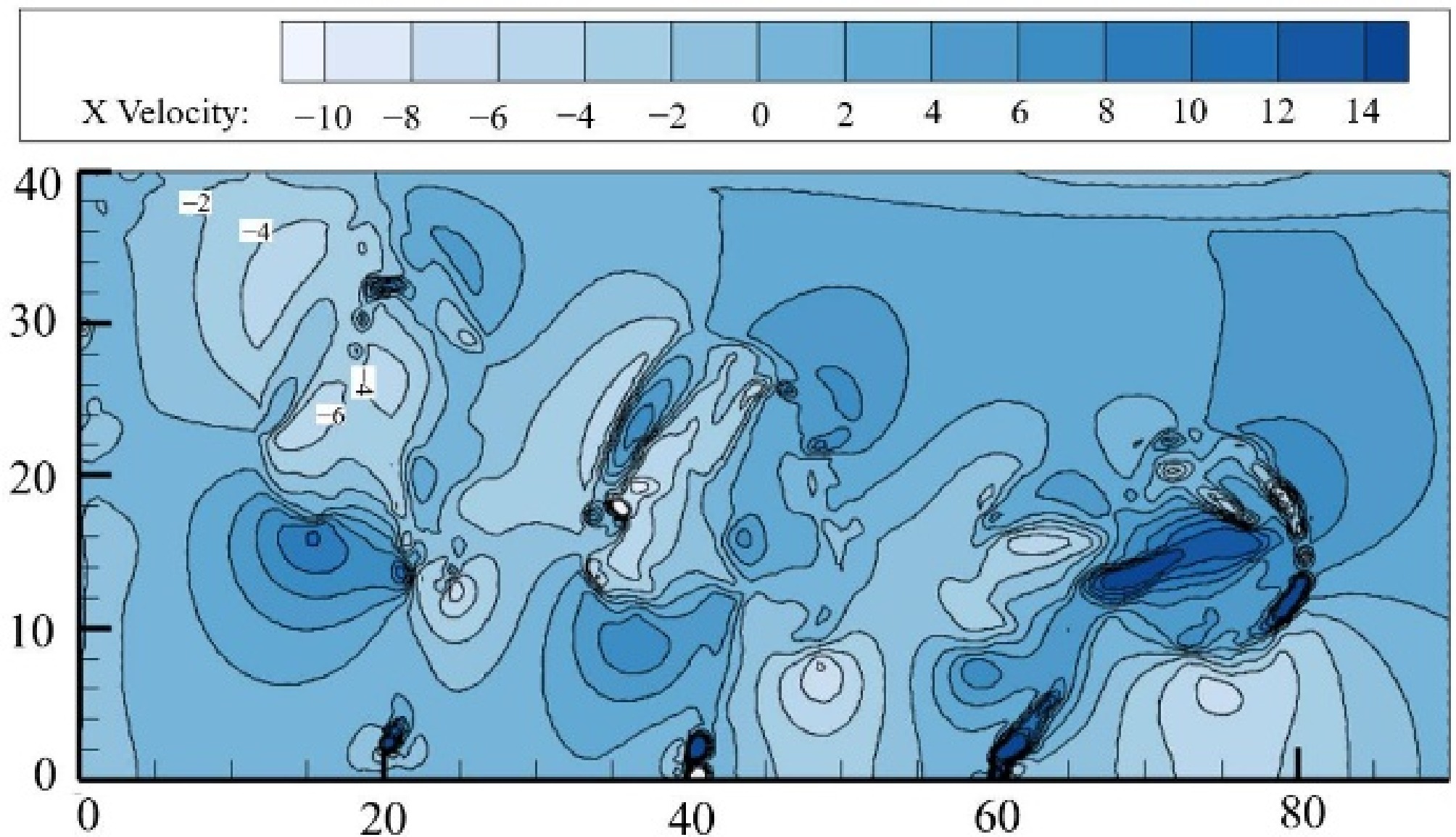
Figure 12.
The morphology of methane plumes under porous leakage[21].
-
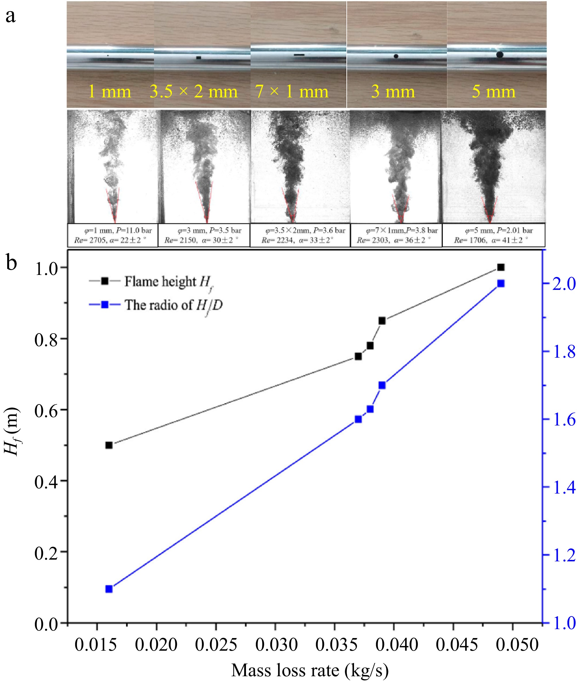
Figure 13.
(a) Different leakage apertures and their leakage gas jet states. (b) Flame height and Hf/D along with the change of mass loss[67].
-
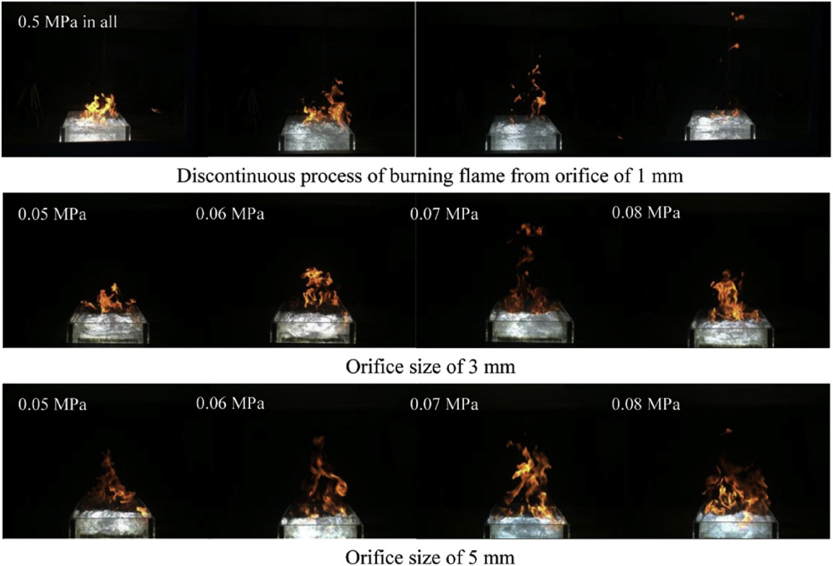
Figure 14.
CH4 burns a flame on the water surface after leaking at different apertures and pressures[22].
-
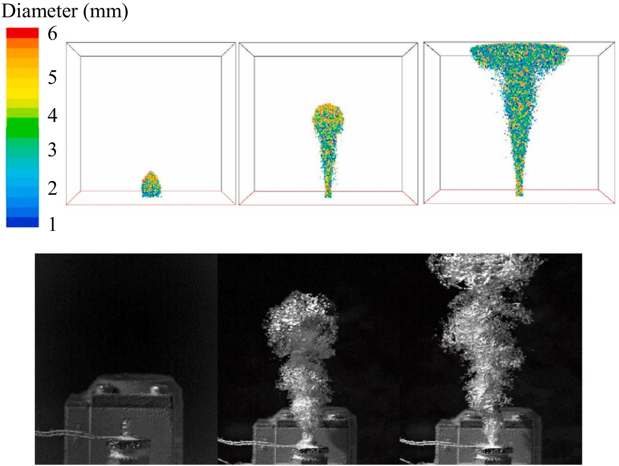
Figure 15.
Evolution of bubble plume after underwater CH4 leakage[65].
-
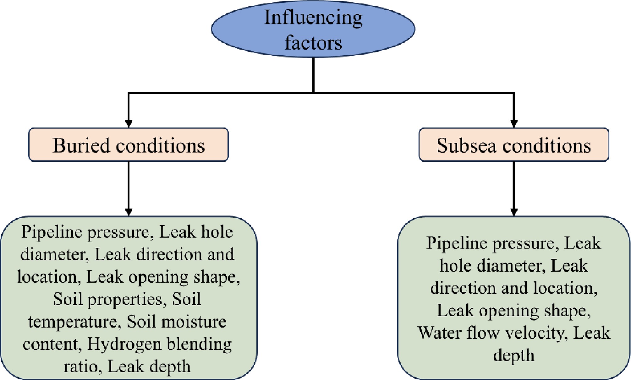
Figure 16.
Influencing factors of natural gas and hydrogen-blended natural gas leaks in buried and subsea environments.
-
State Transportation method Pressure (MPa) Load per carriage (kg) Volume density (kg·m−3) Cost (CN¥/kg) Economic distance (km) Gaseous H2 Long L 20 300−400 14.5 5 < 150 Pipeline 1−4 3.2 0.3 ≥ 500 Liquid H2 Liquid H2 tanker 0.6 7,000 64 13.57 ≥ 200 Solid organic H2 Truck 4 300−400 50 < 150 Table 1.
Comparison of different H2 transportation methods[11].
-
Ref. Research subject Influencing factors Software models Research methods Bu et al.[31] CH4 Leak pressure, leak orifice diameter, pipeline burial depth, soil properties, wind speed, surface structures ANSYS FLUENT Numerical simulation Bu et al.[17] CH4 Soil properties, pipeline operating pressure, pipeline burial depth, leak diameter ANSYS FLUENT Numerical simulation Liu et al.[41] CH4 Leak pressure, pipeline burial depth, leak direction, soil properties, leak orifice diameter ANSYS FLUENT Numerical simulation Liu et al.[42] CH4 Leak pressure, leak orifice diameter, soil properties ANSYS FLUENT Numerical simulation Ren et al.[20] CH4 Seepage pressure, leak orifice diameter, soil properties, soil temperature ANSYS FLUENT Numerical simulation, experiment Zeng et al.[43] CH4 Leak pressure, pipeline leak orifice diameter and position ANSYS FLUENT Numerical simulation Zhang et al.[44] CH4 Leak hole quantity (single vs. double hole comparison) ANSYS FLUENT Numerical simulation Bezaapour et al.[45] CH4 Soil characteristics, slope,moisture content, leak pressure, leak orifice diameter ANSYS FLUENT Numerical simulation Bu et al.[46] CH4 Leak pressure, leak orifice diameter, pipeline burial depth, pipeline diameter, leak direction, soil characteristics ANSYS FLUENT Numerical simulation Wang et al.[27] CH4 Leak orifice size and position, leak pressure, soil properties ANSYS FLUENT Numerical simulation Houssin-Agbomson et al.[19] CH4, H2 Gas type, leak pressure, leak orifice diameter, leak direction, soil characteristics / Experiment Zhou et al.[47] CH4 Leak pressure, leak orifice diameter, soil characteristics ANSYS FLUENT Experiment, numerical simulation Liu et al.[48] H2/CH4 H2 ratio, soil characteristics, wind speed ANSYS FLUENT Numerical simulation Li et al.[49] H2/CH4 Leak pressure, H2 ratio, ground hardening degree, leak orifice diameter, pipeline burial depth ANSYS FLUENT Numerical simulation Wang et al.[50] H2/CH4 Heat transfer coefficient, leak pressure, H2 ratio OLGA Numerical simulation Lu et al.[51] H2/CH4 H2 ratio, leak pressure, soil porosity, leak orifice diameter ANSYS FLUENT Numerical simulation Wu et al.[52] H2/CH4 Leak pressure, leak orifice diameter, soil temperature, soil characteristics, soil moisture content, H2 ratio ANSYS FLUENT Numerical simulation Zhu et al.[18] H2/CH4 H2 ratio, leak pressure, and leak direction ANSYS FLUENT Experiment, numerical simulation Table 2.
Research status of pipeline leakage and diffusion of CH4, H2 and its mixture in the buried scenario.
-
Ref. Research subject Influencing factors Software model Research method Ellethy et al.[57] CH4 Leak orifice diameter, water depth ANSYS FLUENT Numerical simulation Wang et al.[58] CH4 Leak pressure, leak orifice diameter ANSYS FLUENT Numerical simulation Yang et al.[59] CH4 Leak point water depth, leak orifice diameter, leak pressure, ocean current speed ANSYS FLUENT Numerical simulation Chai et al.[60] CH4 Leak orifice diameter, leak rate, water flow velocity ANSYS FLUENT Numerical simulation Wang et al.[61] CH4 Leak rate, water depth ANSYS FLUENT Numerical simulation Ji et al.[21] CH4 Leak velocity, leak orifice diameter, water flow velocity ANSYS FLUENT Numerical simulation Li et al.[62] CH4 Leak velocity, water depth, water flow velocity, leak location ANSYS FLUENT Numerical simulation Yousef Abdulhafed et al.[63] CH4 Leak orifice diameter ANSYS FLUENT Numerical simulation Peng et al.[37] CH4 Leak orifice depth, leak flow rate ANSYS FLUENT Numerical simulation, experiment Cassano et al.[34] CH4 Release depth, release flow rate, ocean current, wind speed ANSYS FLUENT Numerical simulation Zhang et al.[64] CH4 Leak orifice diameter, leak pressure ANSYS FLUENT Numerical simulation Liu et al.[65] CH4 Pressure, leak orifice diameter, water depth ANSYS FLUENT Experiment, numerical simulation Lin et al.[66] CH4 Leak orifice diameter, different leak positions ANSYS FLUENT Numerical simulation Zhang et al.[36] CH4 Water depth, leak orifice diameter, leak pressure / Experiment Zhang et al.[67] CH4 Leak orifice diameter / Experiment Zhu et al.[22] CH4 Leak point water depth, leak orifice diameter, leak pressure / Experiment Table 3.
Research status of pipeline leakage and diffusion of CH4 and H2 and their mixtures in underwater scenarios.
-
Table 4.
Recommended empirical parameters[61].
Figures
(16)
Tables
(4)