-
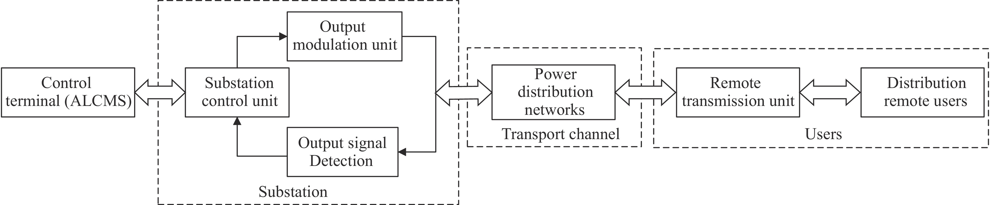
Figure 1.
The logic of the two-way automatic communication system.
-
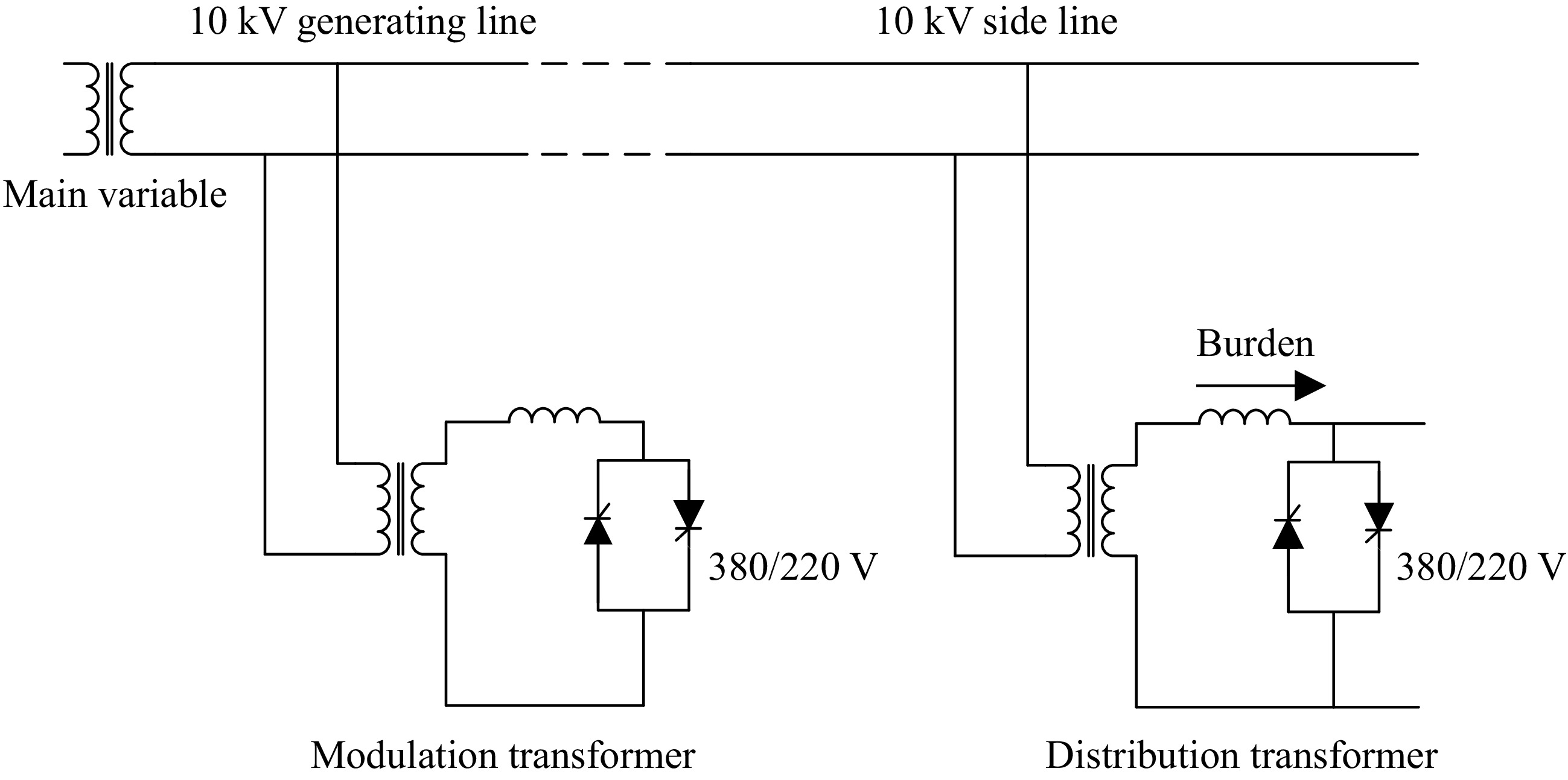
Figure 2.
Typical structure diagram of two-way automatic communication system based on power distribution network.
-
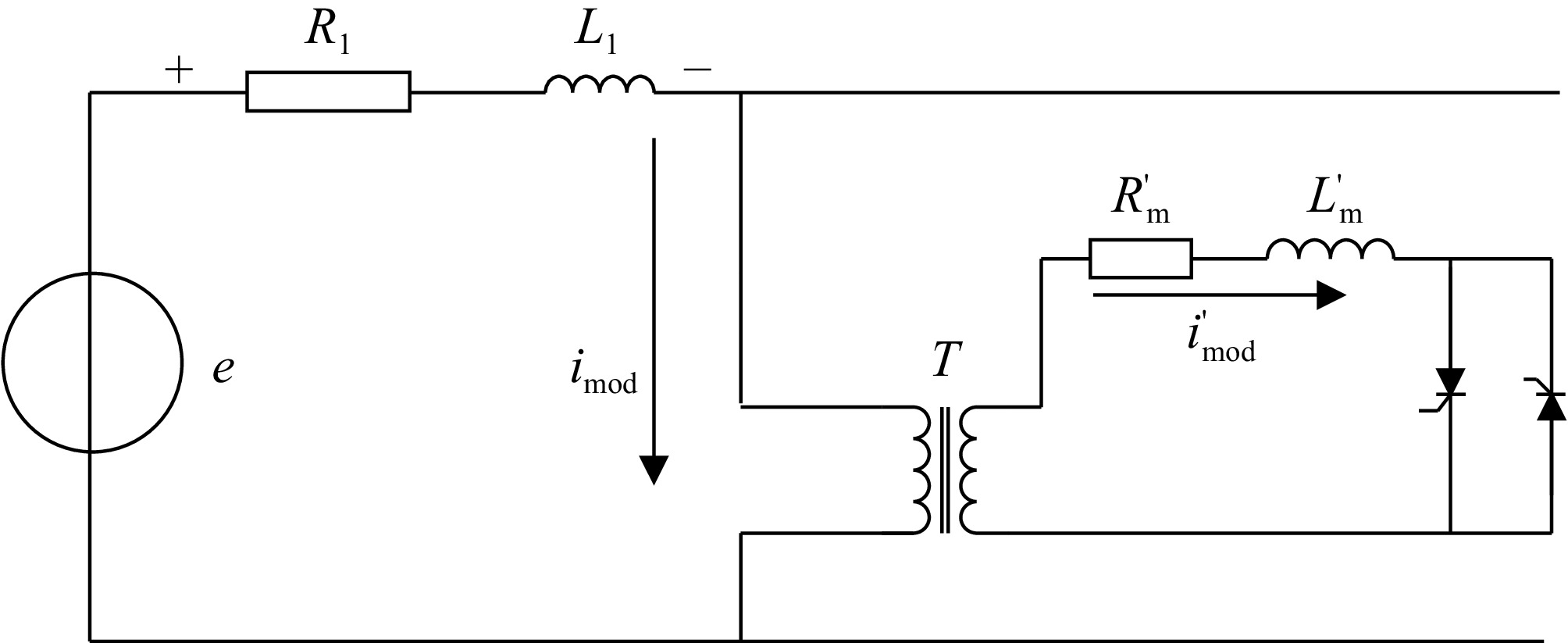
Figure 3.
Outbound signal equivalent modulation circuit.
-
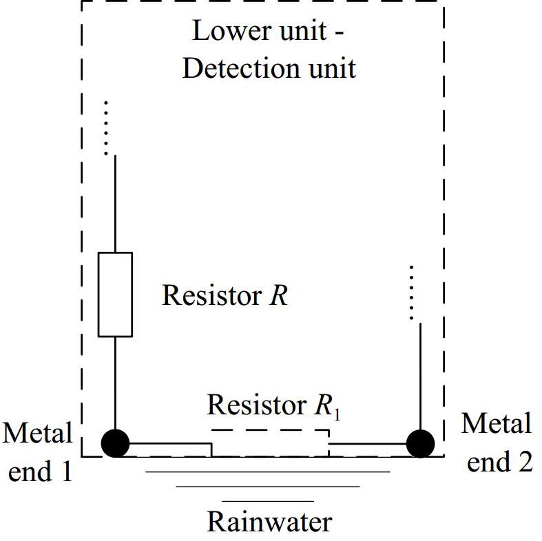
Figure 4.
The principle of detecting water ingress into the bucket.
-
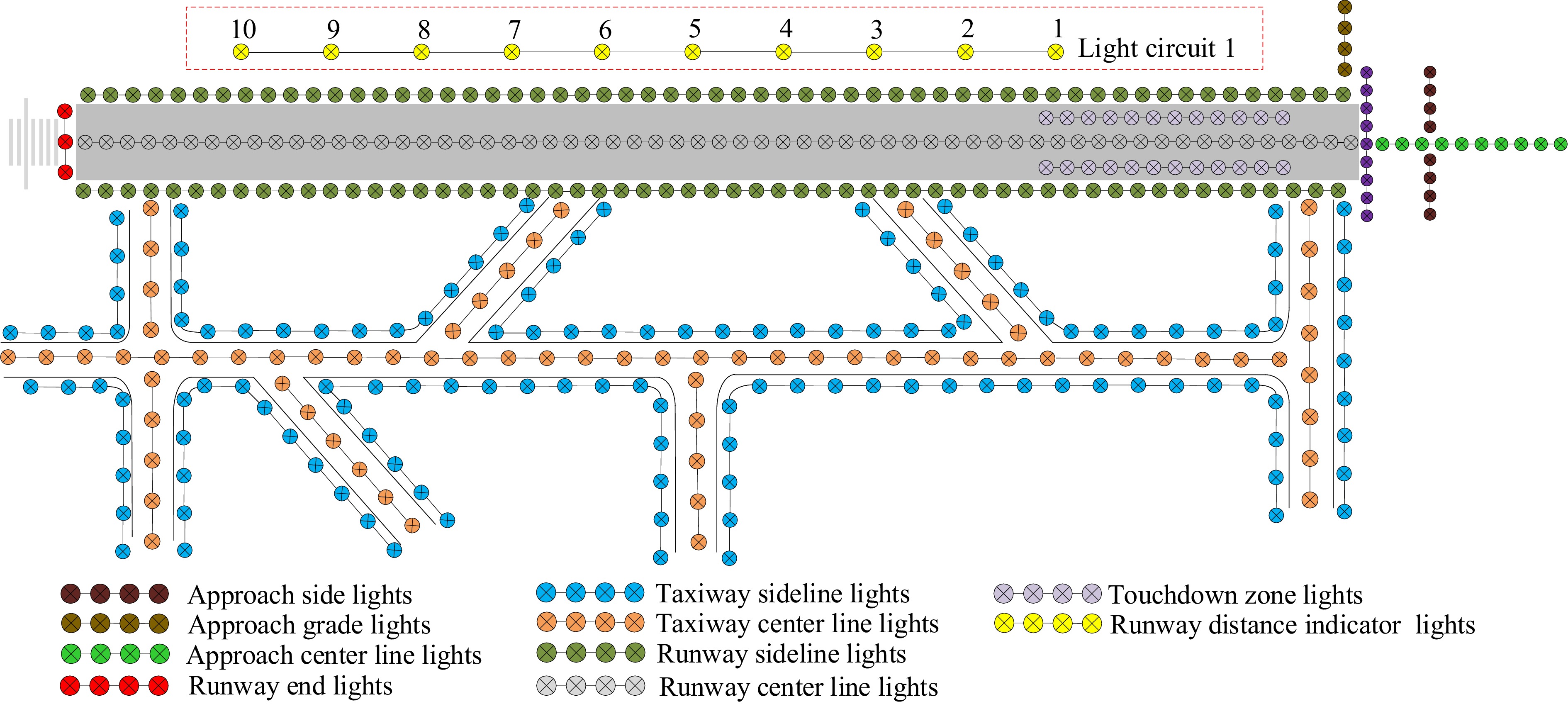
Figure 5.
Structural composition of navigational lighting aid system.
-
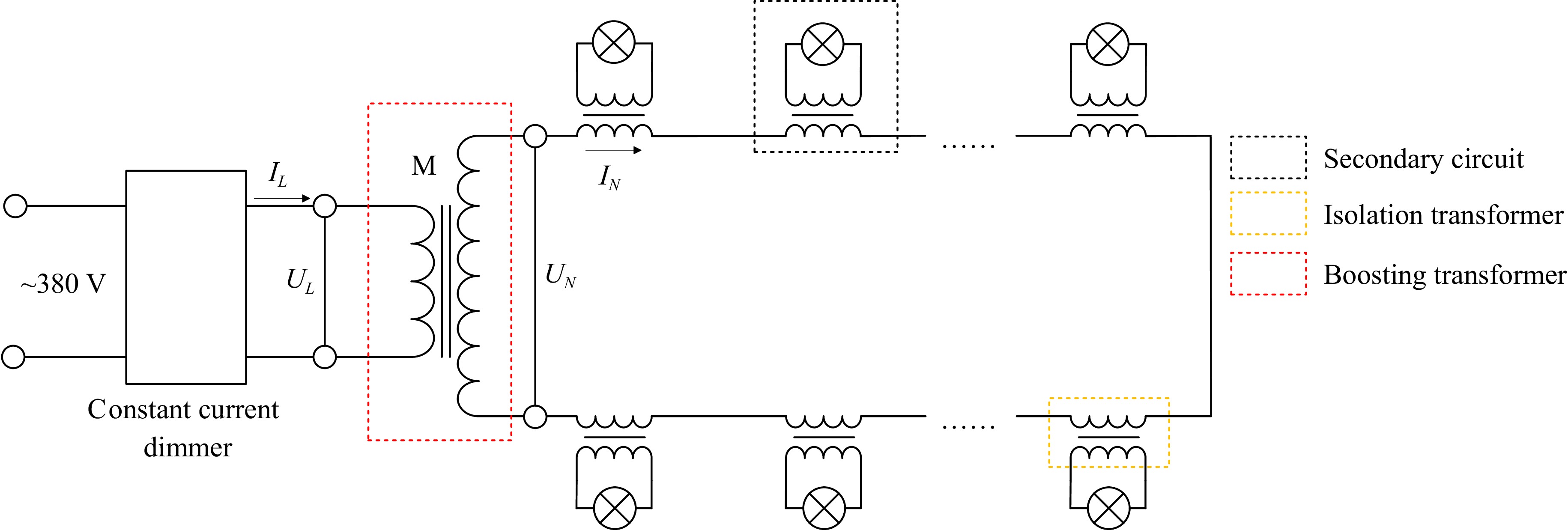
Figure 6.
Principle of control of a light circuit.
-
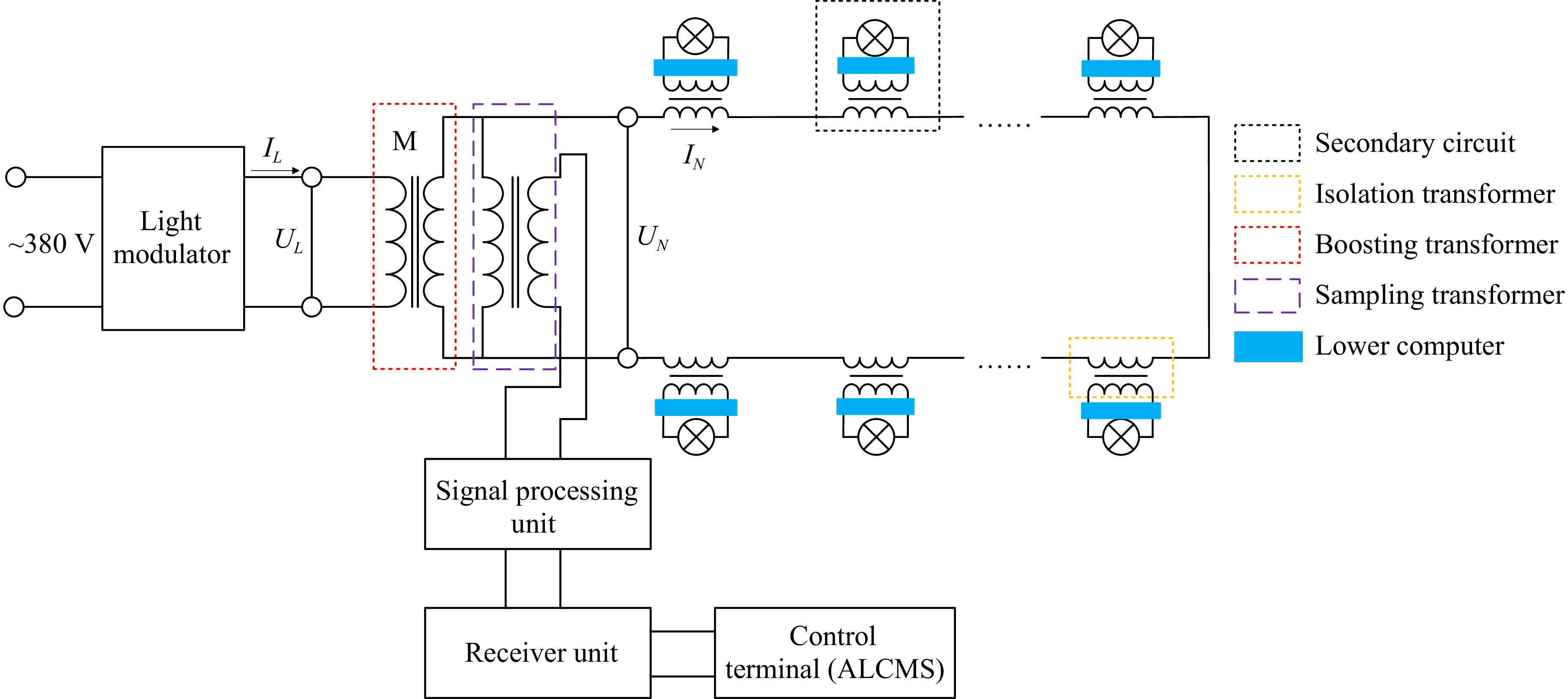
Figure 7.
Principle of light control circuit based on single-lamp monitoring.
-
Experimental cases Simulation experiment results Case 1 A0 01 08 5E A0 02 30 5F A0 03 31 5F A0 04 30 5F A0 05 2F 5F A0 06 30 5F A0 07 31 5F A0 08 2E 5E A0 09 32 5E D0 0A F5 5F Case 2 A0 01 31 61 A0 02 08 5F A0 03 32 5F A1 04 30 5F A0 05 2F 5F A0 06 30 5F A0 07 31 5F A0 08 2E 5E A0 09 32 5E D0 0A F5 5F Case 3 A0 01 03 3A A0 02 17 3D A0 03 16 3D A0 04 15 3C A0 05 15 3C A0 06 15 3C A0 07 16 3D D0 08 14 3B A0 09 16 3B A0 0A F5 3D Case 4 A0 01 21 4D A0 02 20 4D A0 03 22 4C A0 04 20 4B A0 05 20 4B A0 06 20 4C A0 07 21 4C A1 08 1F 4A A0 09 22 4B D0 0A F5 4F Table 1.
Partial experimental results of the system for monitoring lamp status information.
Figures
(7)
Tables
(1)