


-
International civil aviation is growing rapidly. Air transport has become one of the most important modes of transportation for international and domestic travel in recent decades, with the number of passengers expected to reach 8.2 billion by 2037[1]. The rapid development of the aviation industry has put forward higher requirements for the safety of aircraft navigation. The navigational lighting aid system is a visual navigation aid used to guide aircraft landing, taking off, and taxiing. It enhances environmental visibility through the installation of various lamps in and around the airport. This system is critical to the safe operation of aircraft. Once lamps in the system fail, the overall performance degrades, and in serious cases, irreparable disasters may occur[2−4]. At this stage, daily inspection and maintenance have become heavy tasks for the airport. This has placed a serious burden on airport operations. The traditional inspection method no longer meets the demands of the rapidly developing civil aviation industry.
Most researchers have proposed various solutions for the low efficiency of traditional inspection, which are mainly divided into two categories. One category enhances the speed of manual inspection by utilizing new technologies, and the other aims to achieve intelligent inspection via single-lamp intelligent detection. Regarding new technologies, Niblock et al. proposed a model-based feature-matching technique. They identified the status of each lamp with the help of aerial image tracking to evaluate system performance and improve inspection efficiency[5]. Černý et al. proposed using UAVs to check the proper functioning of lamps. They conducted various tests of the system's functionality in a flying laboratory. The results showed that UAVs can improve inspection efficiency and save a significant amount of money[6]. Varying environmental conditions—such as weather changes and lighting variability—can affect the accuracy of UAVs and image processing recognition, thus reducing the reliability of inspections. Therefore, many researchers have begun to explore solutions from the perspective of machine learning. He et al. used AI technology to build a prototype expert system. They evaluated and predicted lamp failures based on lamp performance indicators. The results show that this method can effectively improve the efficiency of manual inspection[7]. Zhao analyzed the lighting data using data mining algorithms to identify anomalies and faults. The accuracy of fault detection and localization is improved by establishing a fault diagnosis model. Although all these methods can improve the efficiency of inspection[8], the technical complexity, cost, and data issues faced in their practical promotion and application in airports still need to be further researched and resolved.
Single-lamp intelligent detection can be a good solution to the applicability problem, but its technical complexity is also a major problem. Zhang et al. proposed utilizing computer and network technology to monitor and control the system online. The composition method of the system was introduced, and meanwhile, the design scheme for its realization was given[9]. Wang et al. automated the inspection through TCP/IP-based Power Line Carrier Communication (PLCC) and Local Area Network (LAN) signal modulation and demodulation communication. This technique avoids the need to lay communication cables and reduces costs[10]. Vidal et al. proposed a method for detecting lamp faults. They identified lamp faults by determining an analytical expression for the resonant frequency of the system, thus avoiding the introduction of harmonic currents in the transformer that can worsen the problem[11]. Yang et al. proposed a single-lamp monitoring system for airport lighting based on broadband power carrier communication technology. The method solves the problems of low communication rate and high communication delay in the traditional method[12].
The existing research has significantly advanced the automation level of the navigational lighting aid system. However, it still needs to be further strengthened in terms of detection accuracy, applicability, and the number of lamp faults detected. This paper explores the use of power line carrier communication to detect lamp fault information, aiming to automate the inspection of the navigational lighting aid system. To address the high noise components in the power supply circuit of the navigational lighting aid system, and to avoid the need for special cables for signal transmission, a two-way automatic communication system is employed. This communication method improves the system's anti-interference capabilities and ensures reliable, stable signal transmission. A comprehensive fault detection system has been developed, capable of identifying six distinct types of faults that may occur in lamps and accurately locating the corresponding faulty components. Based on this approach, an intelligent inspection system has been established. Experimental results confirm that the proposed method effectively detects all six lamp fault types and accurately localizes the faults.
-
Power line carrier communication (PLCC) technology is a technical method for achieving single-lamp intelligent detection. However, during signal transmission, electromagnetic interference— primarily from motors, transformers, and other electrical devices—may affect the stability and reliability of power carrier signals[13,14]. This interference may result in data loss or communication instability. In the navigational lighting aid system, the power supply circuits utilize a series-loop constant current alternating current (AC) chopper configuration. These circuits are characterized by substantial noise components. Meanwhile, the infrastructure at most airports does not support the reconstruction or installation of dedicated signal transmission cables. Considering these technical constraints, single-lamp intelligent detection within such systems necessitates a robust signal transmission method with strong anti-interference capability.
Two-way automatic communication system
-
The main components of the two-way automatic communication system (TWCAS), based on the power distribution network, comprises two parts: the substation, and the control terminal. This structure facilitates the the two-way signal transmission function[15−17]. The substation is responsible for sending and receiving information to and from the control terminal. The sending of information is accomplished via a modulation transformer, whereas signal reception is achieved using current signals collected through a current transformer. The control terminal is responsible for receiving commands from the substation and returning user information. The communication transmission method is shown in Fig. 1. In this system, the channel through which the substation sends information to the users is termed the outgoing channel, while the channel through which the terminal transmits information back to the substation is called the inbound channel. The modulated signals carrying the outgoing and incoming information are called outgoing and incoming signals, respectively.
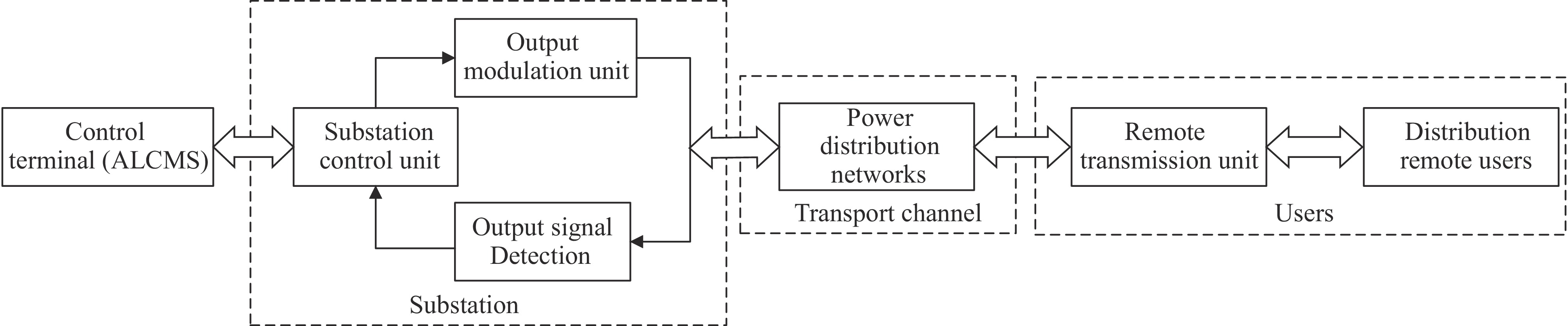
Figure 1.
The logic of the two-way automatic communication system.
The principle of the two-way automatic communication system
-
The two-way automatic communication system uses distribution lines as signal carriers. Figure 2 shows a simplified typical structure. The signal is superimposed on the base wave voltage or current near the zero-crossing point. The specific work process occurs on the 10 kV line voltage near the zero point, where a transient current pulse is modulated via the thryistor on the low voltage side of the signal injection transformer. A weak voltage distortion signal is generated and superimposed on the 10 kV voltage[18,19]. This signal can be received directly across the distribution transformer on the customer side.
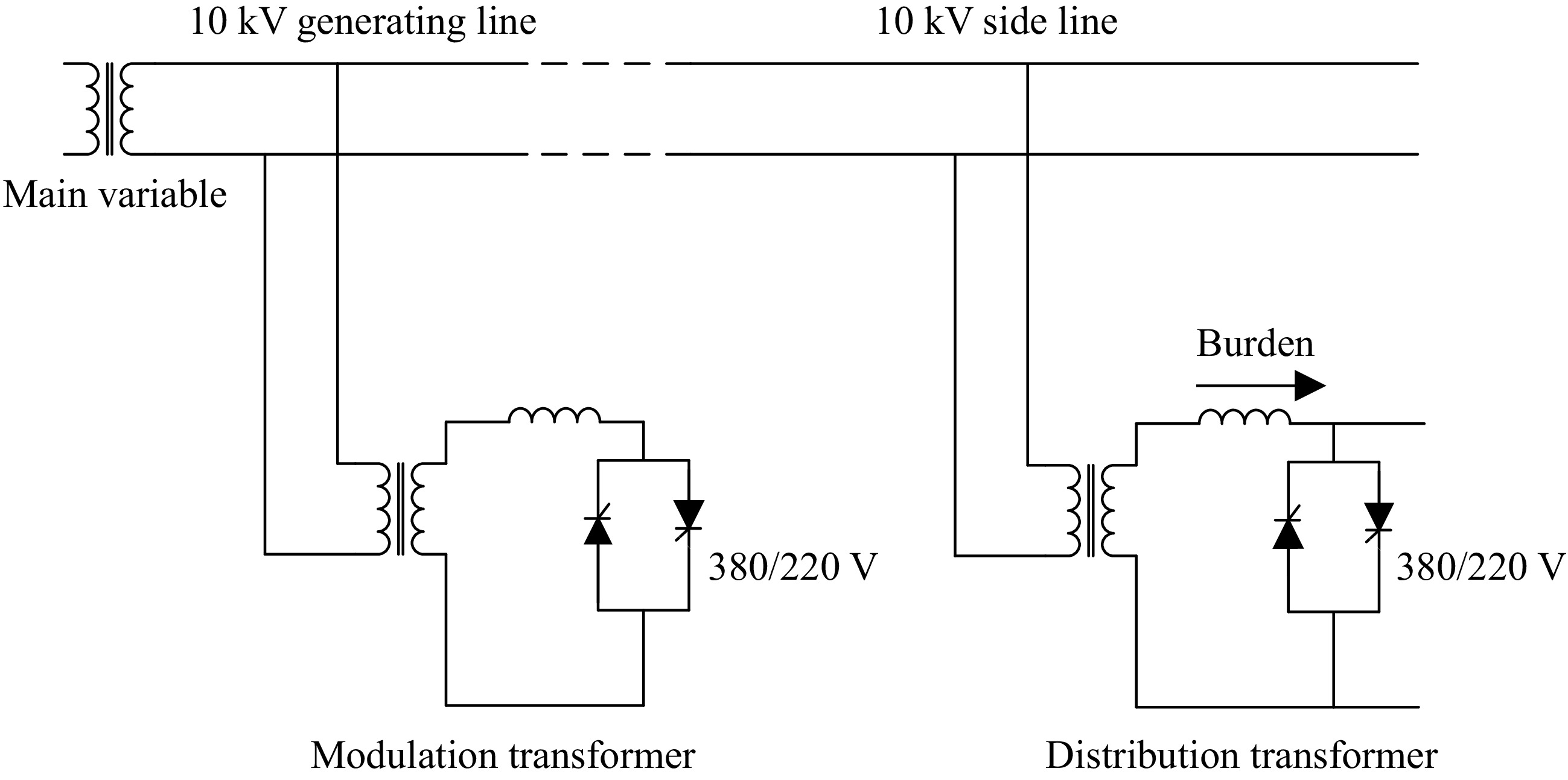
Figure 2.
Typical structure diagram of two-way automatic communication system based on power distribution network.
Modulation and demodulation of signals in the communication process
-
In performing communication, it is important to recognize command messages and detect fault messages. In the two-way automatic communication system, this identification is achieved by modulating and demodulating the signal[20]. The process of transferring information from the substation to the user is called the outbound channel. We illustrate the processing of signals with an example of the outbound process.
Outbound signal modulation principle
-
The modulation process of the outgoing signal can be equated to the modulation circuit shown in Fig. 3. In Fig. 3, R1 and L1 are the secondary-side leakage impedances. The primary voltage of transformer T is 10.5 kV, and the rated voltage of the secondary side is 0.4 kV. The transformation ratio k is calculated to be 26.25.
$ R_{\text{m}}^{'} $ $ L_{\text{m}}^{'} $ 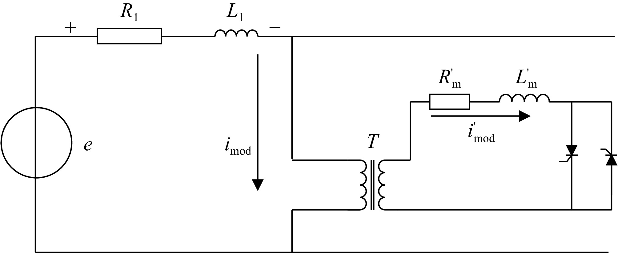
Figure 3.
Outbound signal equivalent modulation circuit.
The current signal i' generated in the modulating loop when the thyristor conducts is:
$ {i^{'}} = \dfrac{{{U_m}}}{{\left| {{Z_m}} \right|}}\sin \left( {\omega t + \alpha - \varphi } \right) - \dfrac{{{U_m}}}{{\left| {{Z_m}} \right|}}\sin \left( {\alpha - \varphi } \right){e^{ - \frac{t}{\tau }}} $ (1) The induced current at the primary side of the transformer is:
$ i = \dfrac{1}{k}{i^{'}} $ (2) When current i passes through R1, L1, the resulting voltage umod is:
$ {u_{\text{mod} }} = \dfrac{{{U_m}}}{{k\left| {{Z_m}} \right|}}\left| {{Z_1}} \right|\sin \left( {\omega t + \alpha - \varphi + {\varphi _1}} \right) + \dfrac{{{U_m}}}{{k\left| {{Z_m}} \right|}}\left( {{R_1} + \dfrac{{{{\text{L}}_1}}}{{L_{\text{m}}^{'}}}R_{\text{m}}^{'}} \right)\sin \left( {\alpha - \varphi } \right){e^{ - \frac{t}{x}}} $ (3) Equation (3) shows three ways in which the signal amplitude can be increased. These are: reducing the modulating transformer ratio, increasing the modulating transformer capacity, or decreasing the size of
$ R_{\text{m}}^{'} $ $ L_{\text{m}}^{'} $ $ R_{\text{m}}^{'} $ $ L_{\text{m}}^{'} $ Outbound signal demodulation principle
-
The demodulation process of a signal in a two-way automatic communication system is a process in which the original digital baseband signal sent is recovered by the filter. In this paper, digital difference algorithm is selected for demodulation operation. This method recognizes message '0' and message '1' based on the position of the grid voltage.
We assume that the signal umod = Asin(ωt + π), and the digital lookup method is to subtract the sampled value at the corresponding position of the previous circumferential waveform from the sampled value at the current circumferential waveform signal position.
Depending on the coding method of the outgoing signal, when the information represented is '1', the output of the digital differential method is:
$ y\left( t \right) = x\left( t \right) - x\left( {t - T} \right) = A\sin \left( {\omega t + \pi } \right) $ (4) When the indicated message is '0', the output of the method is:
$ y\left( t \right) = x\left( t \right) - x\left( {t - T} \right) = - A\sin \left( {\omega t + \pi } \right) = A\sin \left( {\omega t} \right) $ (5) If the phase of the detected output signal is
$ \pi $ $ \sin {\omega _0}t $ $ 2{\varphi _{2PEK}}\left( t \right) = \sin \left( {{\omega _0}t + \Delta \varphi } \right) $ (6) There are two ways of representing the outgoing signal when the phase difference values are
$ \pi $ $ \sin \left( {{\omega _0}t + \Delta \varphi } \right)\sin \left( {{\omega _0}t} \right) = \dfrac{1}{2}\cos \Delta \varphi - \dfrac{1}{2}\cos \left( {2{\omega _0}t + \Delta \varphi } \right) $ (7) Therefore, the output signal of each information is summed according to the difference in the phase difference value, and threshold judgment to realize the demodulation of the signal.
Principle of lamp fault detection
-
Lamps are a crucial component of the navigational lighting aid system. The types of lamps commonly used in airports today include halogen, incandescent, high-intensity discharge (HID), and LED lamps. While the introduction of these various lamp types has improved their stability and reliability, they are still exposed to external environmental conditions for extended periods. Factors such as extreme weather, temperature-induced thermal expansion and contraction, and aircraft-induced vibrations can negatively impact their performance[21−23]. Despite protective shells and inherent advantages, these conditions can still lead to challenges. Lamp failures continue to occur in airports, highlighting the need for further improvements in lamp inspection and maintenance. Some airports have already implemented single-lamp intelligent detection technology. For instance, Guangzhou Baiyun Airport (China), Los Angeles International Airport (USA), and Hong Kong International Airport (China) are utilizing this technology. However, regarding fault detection, current systems can only identify whether the lamps are on or off, flickering, or exhibiting insufficient brightness. Therefore, the current shortcomings of single-lamp fault detection remain evident. The potential impacts of lamp faults are analyzed, classified, and quantified, ultimately leading to the identification of the lamp fault in a visual manner.
Fault types are differentiated by comparing the detected current and voltage values with the standard values. The fault detection principle into two categories, each containing different methods for detecting fault types.
1. Fault type identified by detecting differences in current values
(1) When the lamp is open-circuit, no current passes through the lamp. In this case, the mutual inductance coil built into the detection unit will not detect the current value at the ends of the lamp, resulting in a current value of 0.
(2) For the aging phenomenon of isolation transformer, the analysis is as follows: the constant current dimmer transmit a stable current through the boosting transformer to the main circuit. The isolation transformer is responsible for transferring this current to the secondary circuit. When aging occurs, the performance of the current transmission will be reduced, so the current value obtained by the secondary circuit is less than the standard value.
2. Fault type identified by detecting variability in voltage values
(1) When a short circuit occurs in the lamp, the resistance of the shorted path is very small, resulting in almost no resistance in the circuit. However, there is a 'contact resistance' at the short circuit, so the resistance will be greater than 0, close to zero. In this case, the built-in mutual inductance coil of the detection unit will detect the weak voltage across the lamps.
(2) Oxidization caused by a poorly connected lamp will trigger a number of effects. When a poor contact reaction occurs, it makes fewer contact points in the lamp. This phenomenon makes the cross-sectional area of the poor contact area smaller. According to Eqn (8), this makes the resistance of the lamp larger. This further increases the amount of heat generated in the poor contact area, a phenomenon that is more likely to lead to an oxidation reaction. The oxidation reaction produces oxides that further increase the resistance value, which causes the heat to continue to increase. If this failure is not detected in time, this series of processes will lead to a vicious circle of results. The occurrence of oxidation can be affected by weather conditions. In humid weather conditions, the oxidation reaction is more intense and more oxides are produced resulting in a higher resistance value. In dry weather conditions, less oxide is produced and the resistance increases less. So, the oxidization problem caused by the poor connection of the lamps is observed by looking at the voltage data of the lamps during the cycle. If the voltage value becomes unstable during the cycle, the lamp may be experiencing this failure condition.
$ R = \rho \dfrac{L}{S} $ (8) where,
$ \rho $ (3) When the lamp ages, its resistance changes, the resistance formula is shown in Eqn (8). When the current is constant, the voltage across the lamp will be different from the standard value. This gap is used to illustrate lamp aging failure. The change of resistance is related to the internal structure and type of lamp. Nowadays, most airports use lamp types including halogen lamps, incandescent lamps, high-intensity discharge lamps (HID lamps), and LED lamps. In the case of halogen and incandescent lamps, their internal structure is made of tungsten filaments. When the lamp is in operation, the filament becomes hot due to the passage of electric current, and the tungsten sublimates and adheres to the glass inside the lamp, causing the filament to become thinner and thus increase in resistance. This aging phenomenon causes the lamp to hit a higher than standard value at both ends of the lamp.
(4) For the problem of water in a bucket (we assume that the device holding the detection unit is a bucket), we analyze the following: fault detection of all lamps is realized by the detection unit set up in the bucket. We set two metal ends at the bottom of the detection unit (Fig. 4). Metal end 1 is connected to resistor R, and metal end 2 is grounded. When water enters the bucket and contacts both ends, impurities or minerals in the water ionize, making the water conductive. This conductivity introduces resistance R1 in the resulting circuit. Pure water does not form resistance, but the ionized water reduces the voltage across resistor R below the standard value.
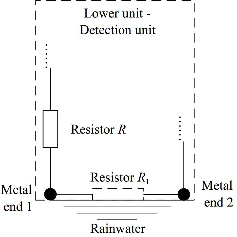
Figure 4.
The principle of detecting water ingress into the bucket.
This section presents a schematic analysis of the six fault detection types. The subsequent section elaborates on how these faults are quantitatively identified via computer-based analysis.
Establishment of intelligent inspection system
-
To verify the feasibility of our proposed method, lighting circuit 1 of an airport's navigational lighting aid system was selected for simulation experiments. Figure 5 shows some of the subsystems in the navigational lighting aid system of an airport.
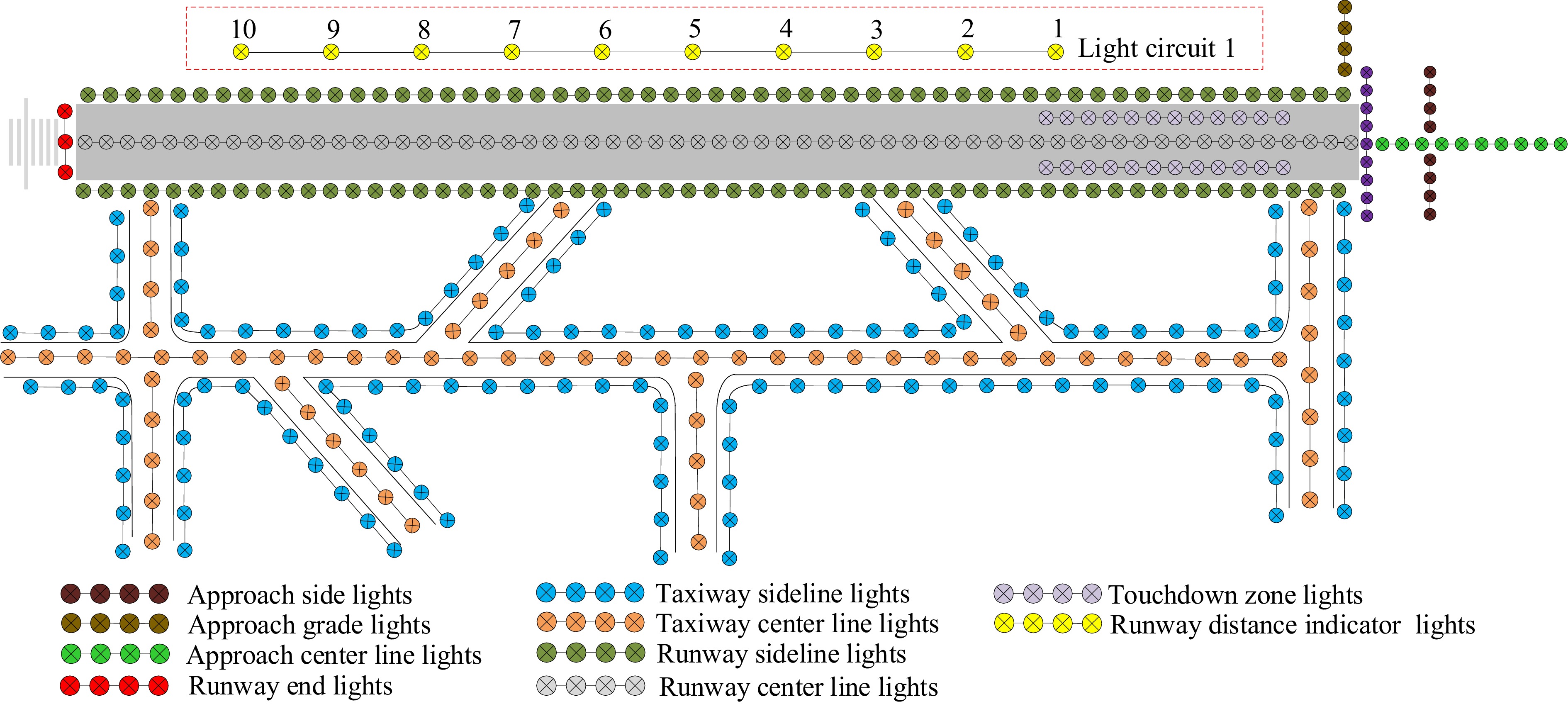
Figure 5.
Structural composition of navigational lighting aid system.
Basic circuits for the realization of intelligent inspection
-
Traditionally, the navigational lighting aid system requires manual inspection to check the status of each lamp. Figure 6 shows the light circuit controlled by a constant current dimmer. The traditional navigational lighting aid system only provides the environmental basis for the realization of intelligent inspection. In Fig. 6, the loop current IN is determined by the voltage UL at the primary terminal of the boosting transformer. Assuming that the total loop load is Z and the ratio of the boosting transformer is M. In the ideal case, the current in the lighting loop is then given by Eqn (9).
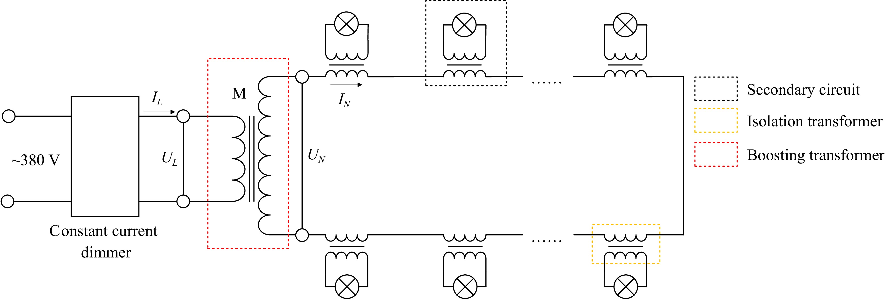
Figure 6.
Principle of control of a light circuit.
$ {I_N} = \dfrac{{{U_N}}}{Z} = \dfrac{M}{Z}{U_L} $ (9) To build the single-lamp monitoring system to realize intelligent detection based on the method proposed in this paper. The first step is to enable the dimmer to adjust the light circuit. To achieve this, a basic control circuit is constructed with the help of some equipment. The details of these equipment are shown in Supplementary Fig. S1.
Establishment of single-lamp monitoring system
-
Based on the intelligent detection principle in the method section of this paper, improvements were made to the lighting circuit depicted in Fig. 6. The modified light circuit is shown in Fig. 7. A detection unit is connected in parallel with each lamp to be responsible for detecting the fault information of the corresponding lamp during the inspection process. Additionally, a sampling transformer is connected in parallel with the main circuit. A signal processing unit is connected to the secondary coil of the sampling transformer. The signals generated during the communication process are transmitted to the control terminal via a receiver unit after signal processing. Please note that the receiving unit receives information in both directions. The sampling transformer, signal processing unit, and receiver unit collectively form the central computer. The control terminal is called the upper computer, while the detection unit is called the lower computer. Physical drawings of both the central and lower computers used in the experiments are provided in Supplementary Fig. S2.
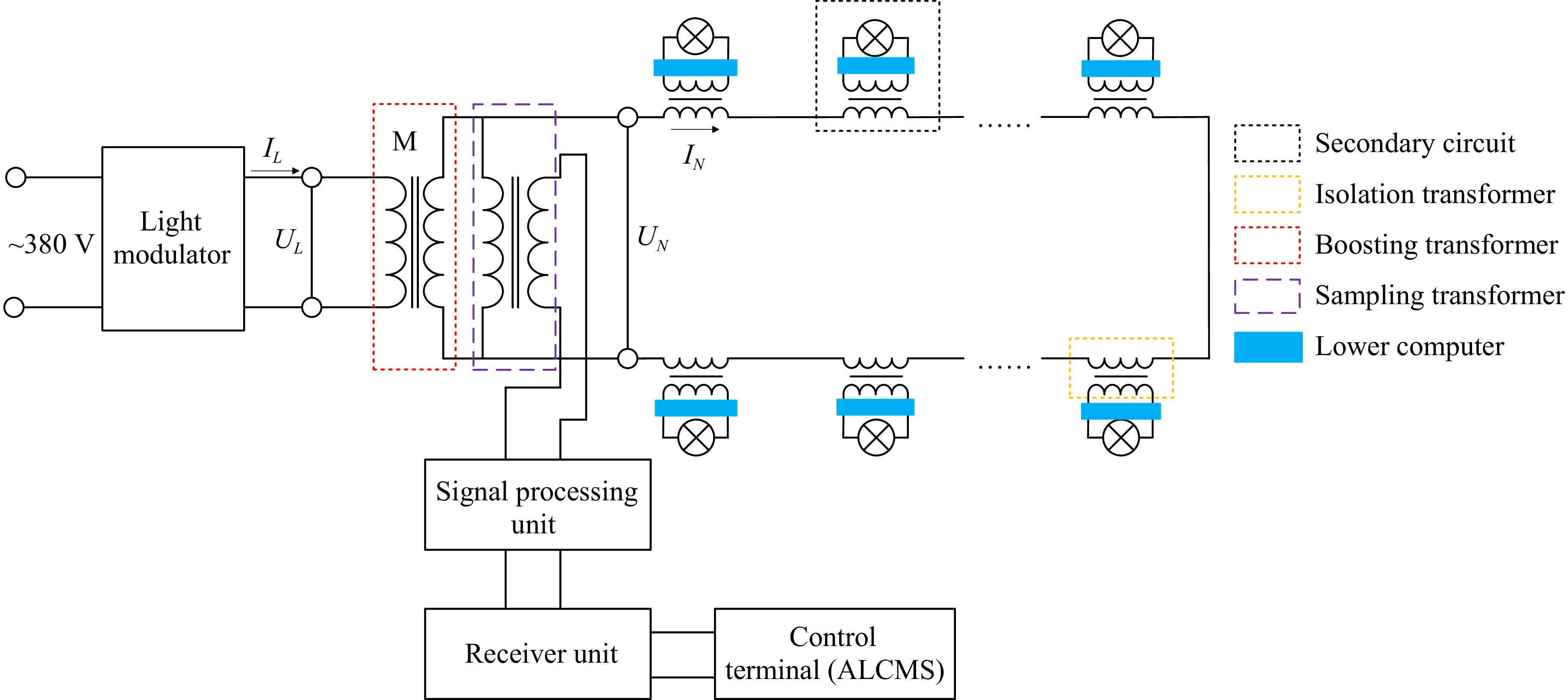
Figure 7.
Principle of light control circuit based on single-lamp monitoring.
The sampling transformer has three roles in the process of signal transmission:
● Isolation role: it isolates the process of detecting fault information from the process of information processing, reducing the interaction between them.
● Information coupling: it transmits the information detected by the detection unit and ensures the quality of the signal.
● Voltage reduction: Since signal processing has certain requirements for the voltage of the circuit, when transmitting the information detected by the detection unit through the power line, it is necessary to perform a voltage reduction operation between arriving at the signal processing unit.
The upper computer is primarily used to send inspection commands and to recognize the fault type based on the received information. In the process of signal transmission, any information that needs to be identified must be presented in string form. The sent string information and the actual meaning it represents are shown in Supplementary Table. S1. To illustrate the meaning of receiving information strings, consider the string 'A0 02 30 5F'. 'A0' indicates a separator number followed by information about the lamp. It also shows that the lamp is properly connected to the light circuit it is on. '02' indicates lamp number. '30 5F' denotes the voltage and current of the secondary circuit, respectively.
-
The simulation experiment was conducted using the established intelligent detection system, and the results are output via the stc-isp-v6.91K software. In a real environment, lamp failures occur randomly, a process that can be prolonged. This paper's goal is solely to confirm the feasibility of the system. The work was performed by two groups of people. Note that the information of the two groups of people is not interoperable until the end of the conducted test. One group set up random faults on 10 lamps unknown to the other group. After the setup, the other group conducts the experiment and judges the feasibility of the system based on the experimental results. Some of the experimental cases were selected, and the experimental results are shown in Table 1.
Table 1. Partial experimental results of the system for monitoring lamp status information.
Experimental cases Simulation experiment results Case 1 A0 01 08 5E A0 02 30 5F A0 03 31 5F A0 04 30 5F A0 05 2F 5F A0 06 30 5F A0 07 31 5F A0 08 2E 5E A0 09 32 5E D0 0A F5 5F Case 2 A0 01 31 61 A0 02 08 5F A0 03 32 5F A1 04 30 5F A0 05 2F 5F A0 06 30 5F A0 07 31 5F A0 08 2E 5E A0 09 32 5E D0 0A F5 5F Case 3 A0 01 03 3A A0 02 17 3D A0 03 16 3D A0 04 15 3C A0 05 15 3C A0 06 15 3C A0 07 16 3D D0 08 14 3B A0 09 16 3B A0 0A F5 3D Case 4 A0 01 21 4D A0 02 20 4D A0 03 22 4C A0 04 20 4B A0 05 20 4B A0 06 20 4C A0 07 21 4C A1 08 1F 4A A0 09 22 4B D0 0A F5 4F In Table 1, Case 1 demonstrates two phenomena: (1) The voltage value of Lamp #1 is significantly lower than that of the other lamps, and the voltage value is very small. This phenomenon indicates that a short-circuit fault has occurred in Lamp #1, and (2) The 'A0' symbol of Lamp #10 has changed to 'D0', which indicates that this secondary circuit connection of Lamp #10 is not normal, and the lamp may have an open-circuit roadblock.
All detection results for lamps with fault characteristics and the results are listed in Supplementary Table S2.
The intelligent inspection system that has been developed is a lighting circuit controlled by a constant current dimmer. The experimental results show that when detection is performed, the intelligent inspection system is able to accurately detect the lamps that are faulty and is able to detect the specific type of fault. The intelligent inspection system in this paper is a lighting circuit controlled by the upper computer. A structural diagram of a fully realized intelligent detection of the future airport navigation lighting aid system is provided in Supplementary Fig. S3. It needs to be clarified that this system can only improve the efficiency of manual inspection at this stage, and cannot fully replace manual labor.
-
This study demonstrates that an intelligent detection system based on two-way communication can significantly improve the accuracy and efficiency of airport navigation light fault detection. Compared with the existing single-light detection technique, the system offers superior anti-interference capability and a broader fault type coverage, better suited to the needs of complex environments[9]. However, the system has not yet covered the effects of external object shading or extreme weather on lamps, which may lead to missed detections (see Voskaki et al. climate risk study[23]). For practical deployment, it is recommended to link this system with airport tower management systems to share fault information in real-time, reducing emergency response time, as demonstrated by the pilot experience at Los Angeles International Airport. Future work may explore multi-sensor fusion strategies, but priority should be given to validating the stability of the core functionality of this study in real-world scenarios.
-
This paper establishes an intelligent inspection system, a lighting circuit controlled by a computer terminal. The purpose is to monitor the status of lamps in the airport navigational lighting aid system and to realize the rapid identification of fault types and the accurate localization of faulty lamps. The problems of limited fault type detection in single-lamp monitoring techniques, increased noise in lighting circuits, and the requirement to reset power lines for signal transmission at this stage are addressed. Power line carrier technology is proposed as the medium, leveraging the strong anti-interference capabilities of two-way automatic communication technology, to achieve single-lamp intelligent detection. Based on the proposed method, an intelligent inspection system is constructed. The proposed method is verified through simulation experiments. The results demonstrate that the system accurately identifies the fault conditions of lamps and locates faulty lamps in the navigational lighting aid system.
This work is supported by Tianjin Education Commission Research Program Project (2024KJ094).
-
The authors confirm contribution to the paper as follows: methodology: Chang X, Yang W; conceptualization, resources, supervision, data curation: Chang X; investigation: Chang X (lead), Yang W (lead), Wang X; validation: Yang W; writing - original draft: Yang W (lead), Wang X; writing - review & editing: Chang X (lead), Yang W (equal), Wang X (supporting). All authors reviewed the results and approved the final version of the manuscript.
-
Data sharing is not applicable to this article as no new data were created or analyzed in this study.
-
The authors declare that they have no conflict of interest.
- Supplementary Table S1 Practical meanings represented by send command strings.
- Supplementary Table S2 Relationship between lamp fault type and message string.
- Supplementary Fig. S1 Composition of equipment for constructing intelligent inspection circuit.
- Supplementary Table. S1
- Supplementary Fig. S2 The core equipment in the intelligent inspection system (a) central computer (b) lower computer.
- Supplementary Fig. S3 Structure of intelligent inspection system with multiple light circuits.
- Copyright: © 2025 by the author(s). Published by Maximum Academic Press, Fayetteville, GA. This article is an open access article distributed under Creative Commons Attribution License (CC BY 4.0), visit https://creativecommons.org/licenses/by/4.0/.
-
About this article
Cite this article
Chang X, Yang W, Wang X. 2025. Intelligent detection method of multi-fault airport navigational lamps based on two-way automatic communication. Digital Transportation and Safety 4(2): 141−147 doi: 10.48130/dts-0025-0016 

Intelligent detection method of multi-fault airport navigational lamps based on two-way automatic communication
- Received: 15 November 2024
- Revised: 11 March 2025
- Accepted: 07 April 2025
- Published online: 27 June 2025
Abstract: Navigational lighting aid systems are critical to ensuring the safety of aircraft operations. To ensure the lighting rate of lamps, the daily inspection and maintenance have become significant tasks for the airport. Enhancing airport intelligence and reducing the operational burden on airports are essential for promoting their rapid development. Therefore, we propose using power line carrier communication as the medium, employing two-way automatic communication technology to enable single-lamp intelligent detection. This method overcomes the shortcomings of the traditional single-lamp monitoring technology in terms of weak anti-interference capability and limited fault detection types. To verify the method's feasibility, we built an intelligent inspection system. The simulation experiment results show that the intelligent inspection system, established based on our proposed method, can accurately identify the lamp fault types and perform fault-lamp localization.