-
Figure 1.
The scenarios of (a) before, and (b) during the fire or explosion of the underground storage tank (Credit: World Wide Web).
-
Figure 2.
Schematic diagram of the (a) experimental device, the (b) needle puncture film equipment, and (c) PET film.
-
Figure 3.
Pressure response under two depressurization modes.
-
Figure 4.
The correlation curve between medium temperature and pressure.
-
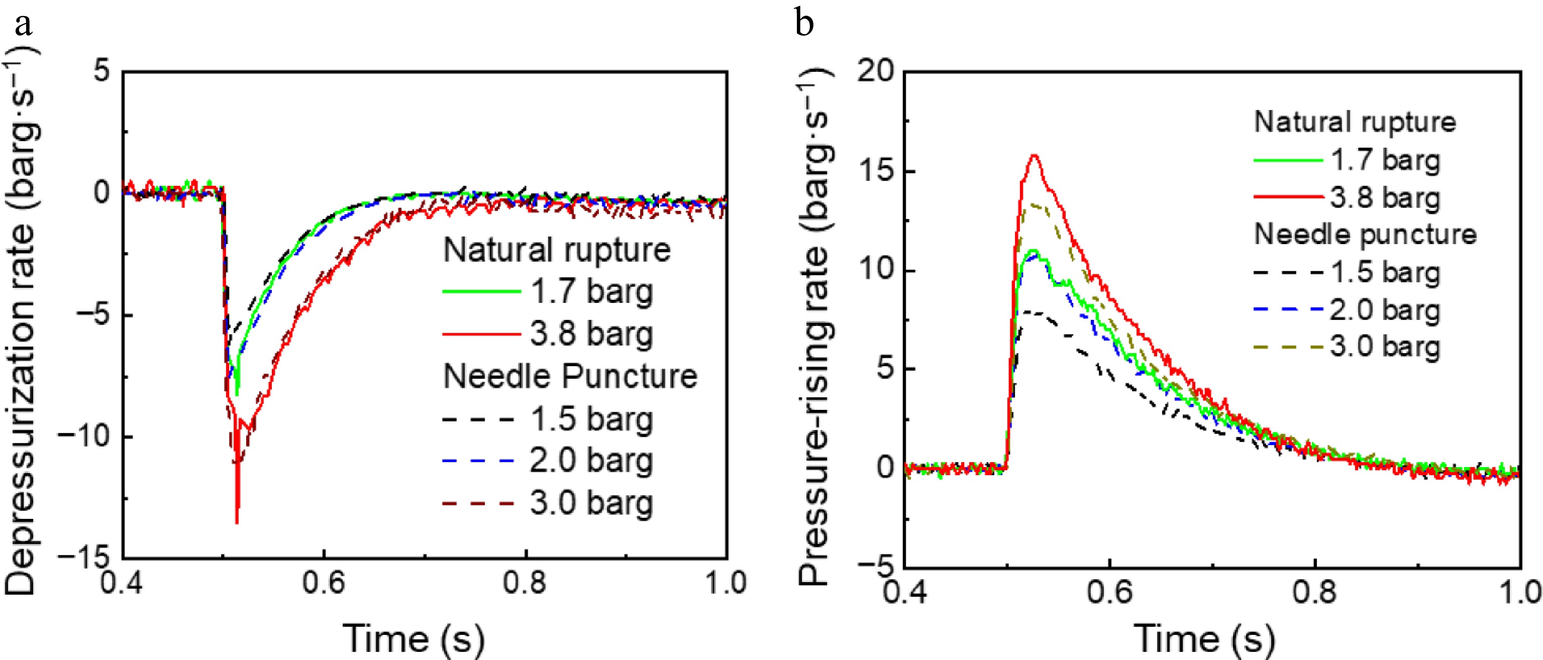
Figure 5.
The depressurization rate in the (a) storage tank, and the (b) pressurization rate in the explosion-vented tank under the depressurization mode of natural rupture and needle puncture.
-
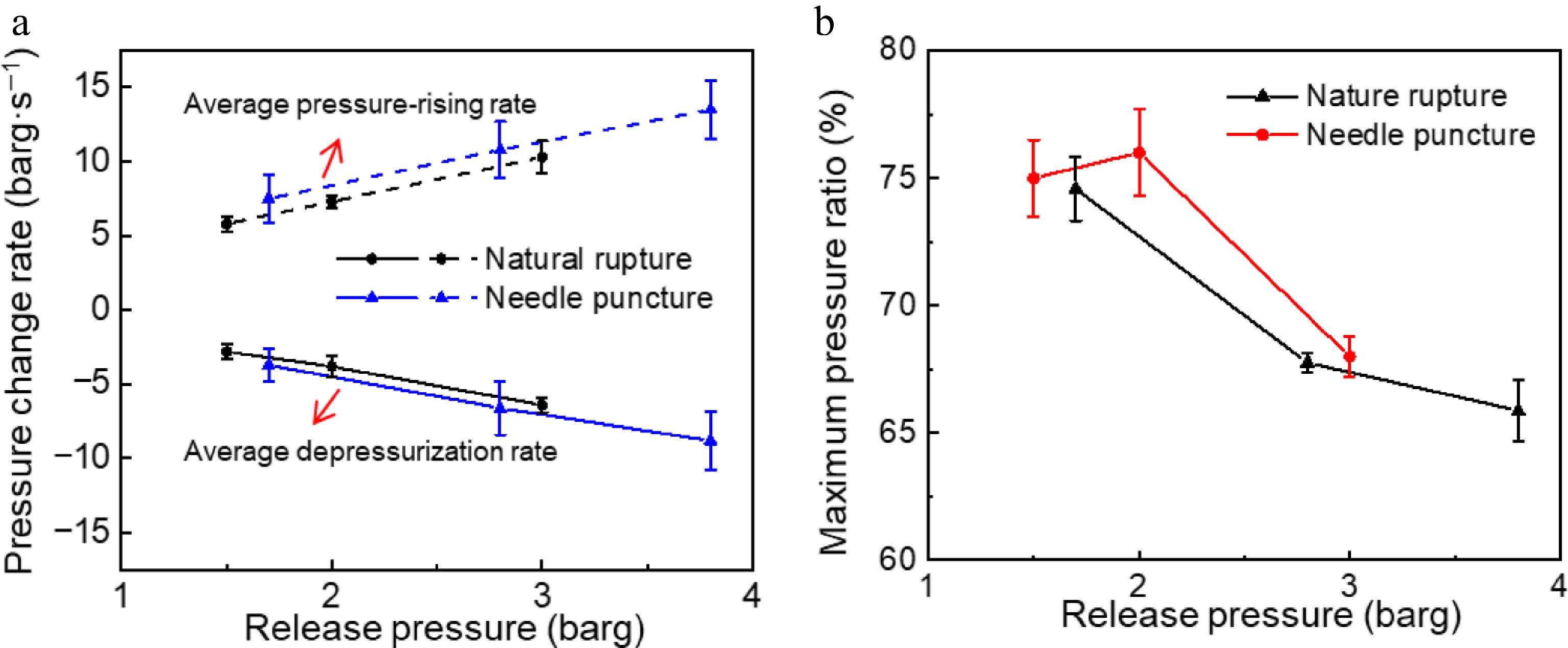
Figure 6.
The effect of initial superheat on leakage parameters of storage tank and explosion-vented tank under different depressurization modes.
-
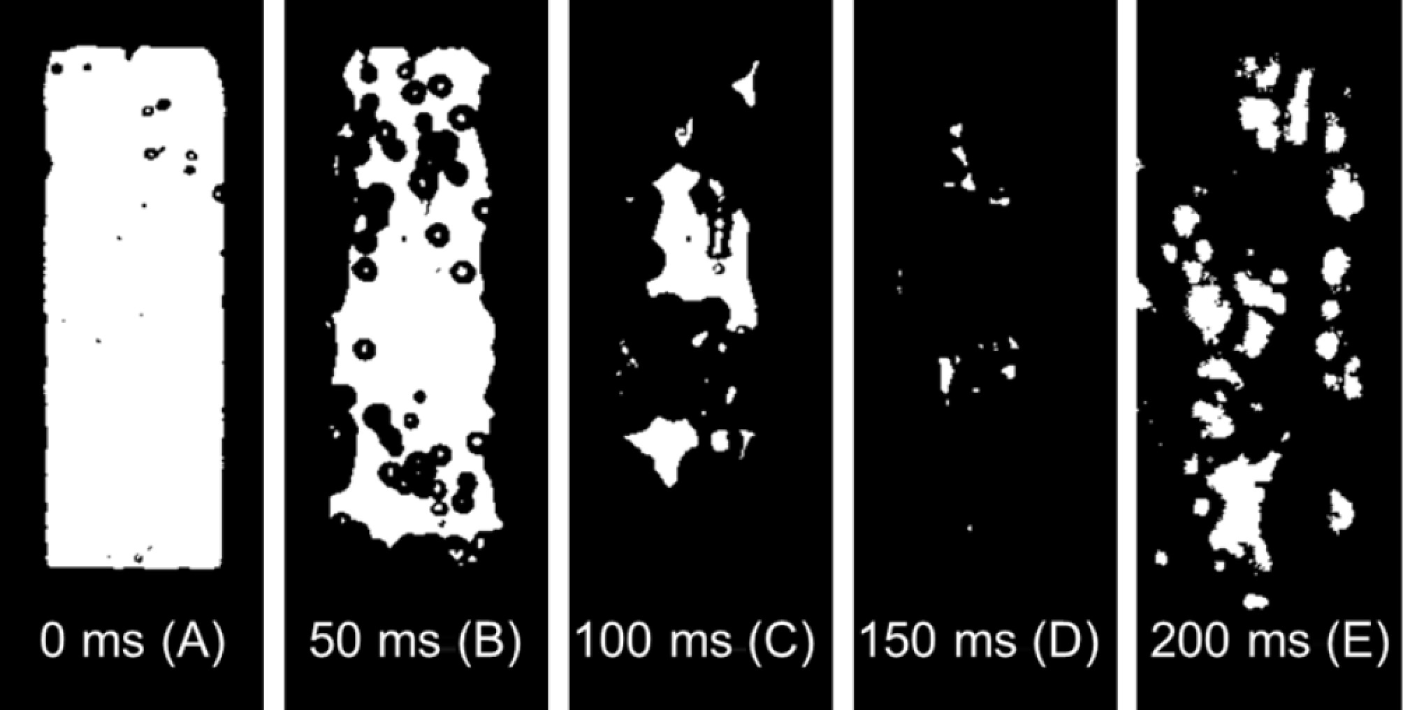
Figure 7.
Evolution of two-phase flow in the storage tank at 3 barg.
-
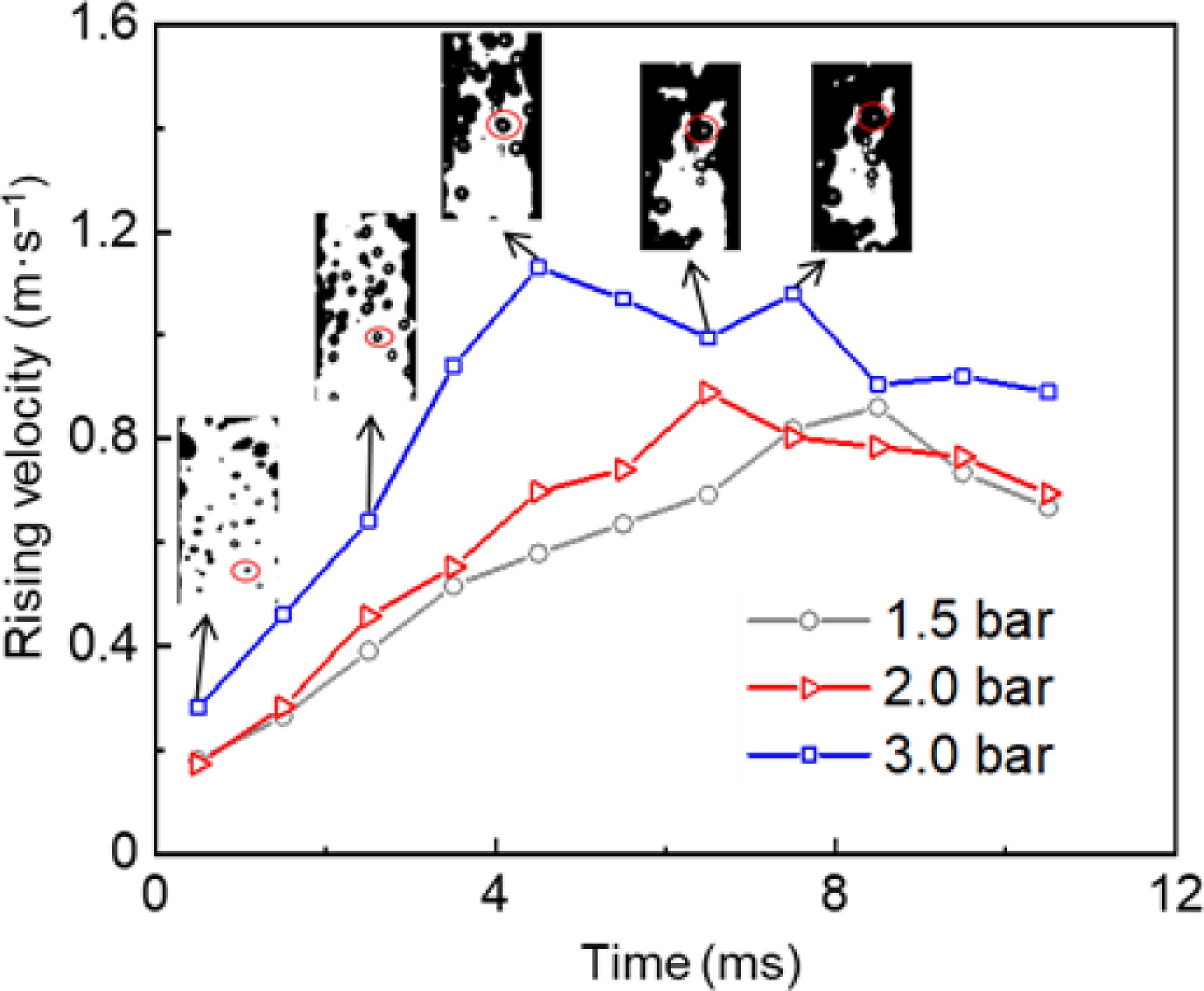
Figure 8.
Bubble rise velocity under different release pressures.
-
Figure 9.
Two-phase flow leakage process within 0.4 ms.
-
Figure 10.
(a) Rupture pressure, and (b) tear area of PET film with different thicknesses.
-
Category Fill level Discharge area
(cm2)PET thickness
(mm)Release pressure
(barg)Nature rupture 70% 9.6 0.025 1.7 ± 0.2 0.038 2.4 ± 0.3 0.05 2.8 ± 0.2 0.075 3.8 ± 0.3 0.1 4.6 ± 0.1 Needle puncture 70% 9.6 0.025 1.5 0.038 2.0 0.075 3.0 Table 1.
Experimental conditions.
Figures
(10)
Tables
(1)