-
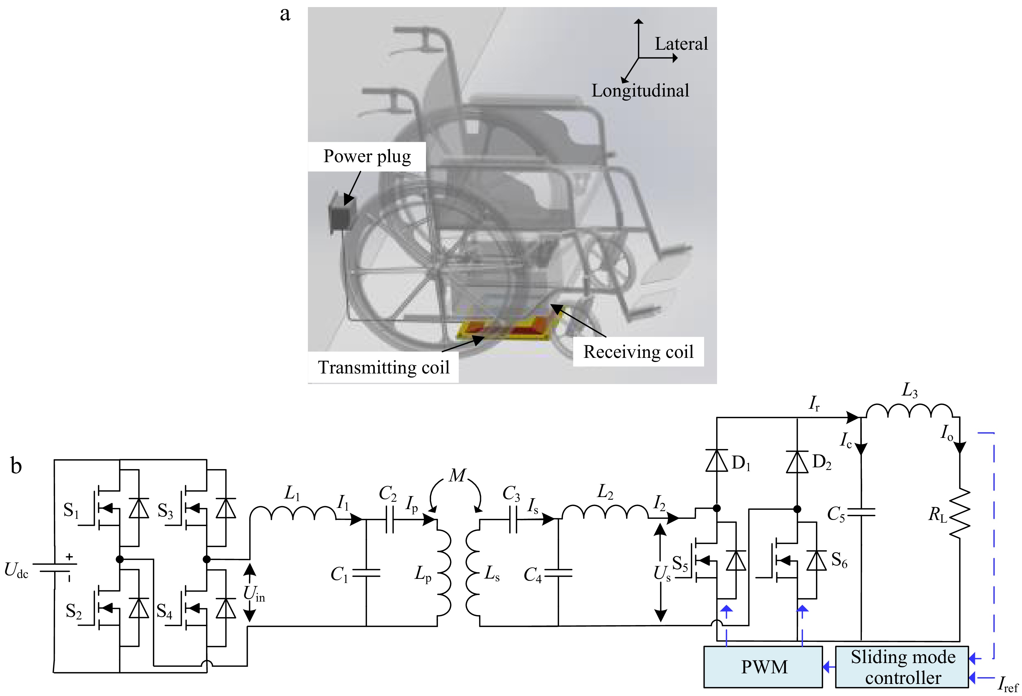
Figure 1.
Wireless charging frame for electric wheelchairs. (a) Wireless charging model. (b) The WPT system with dual-side LCC resonant compensation network.
-
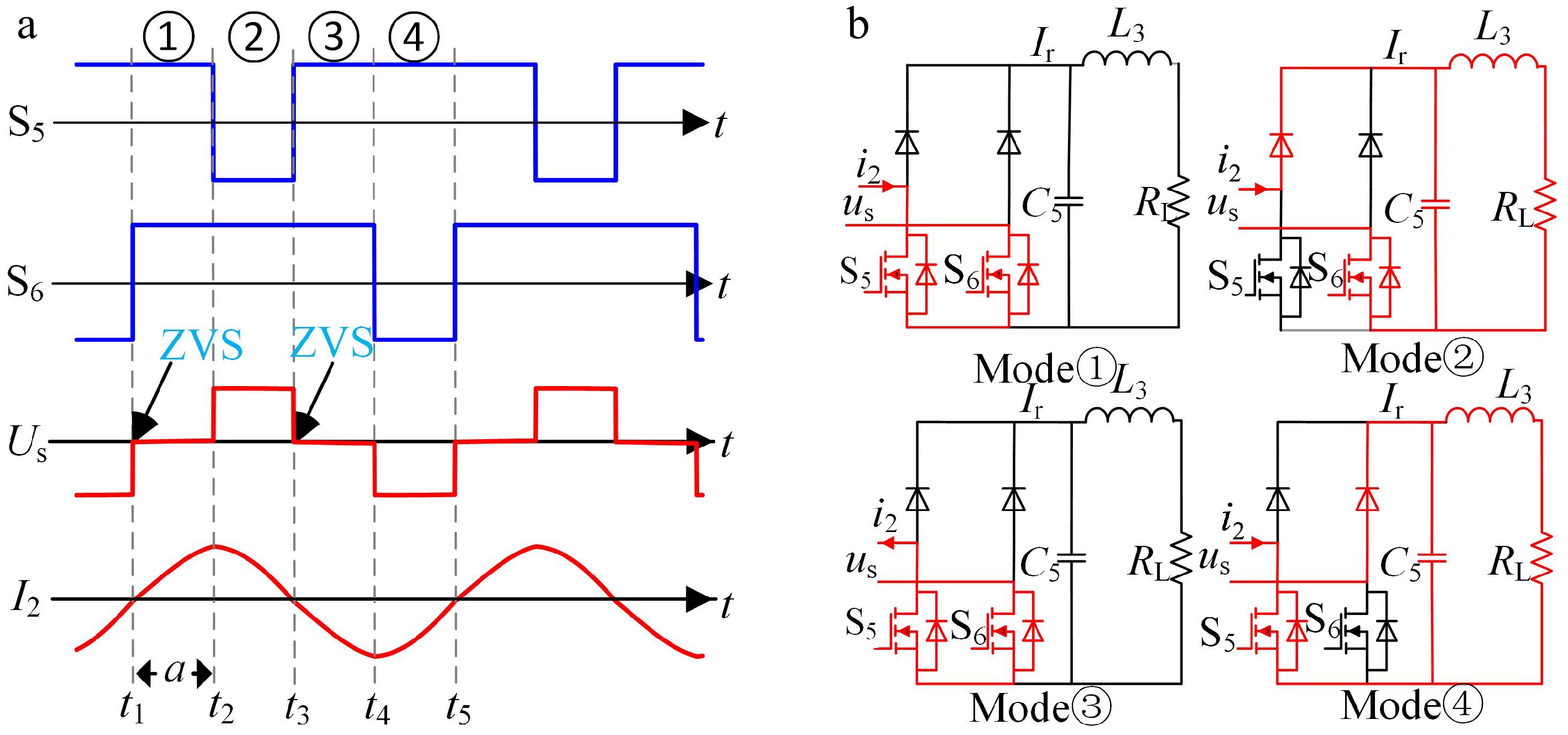
Figure 2.
Mode analysis of controlled rectifier operation. (a) Pulse phase difference of the rectifier. (b) Modal circuit analysis.
-
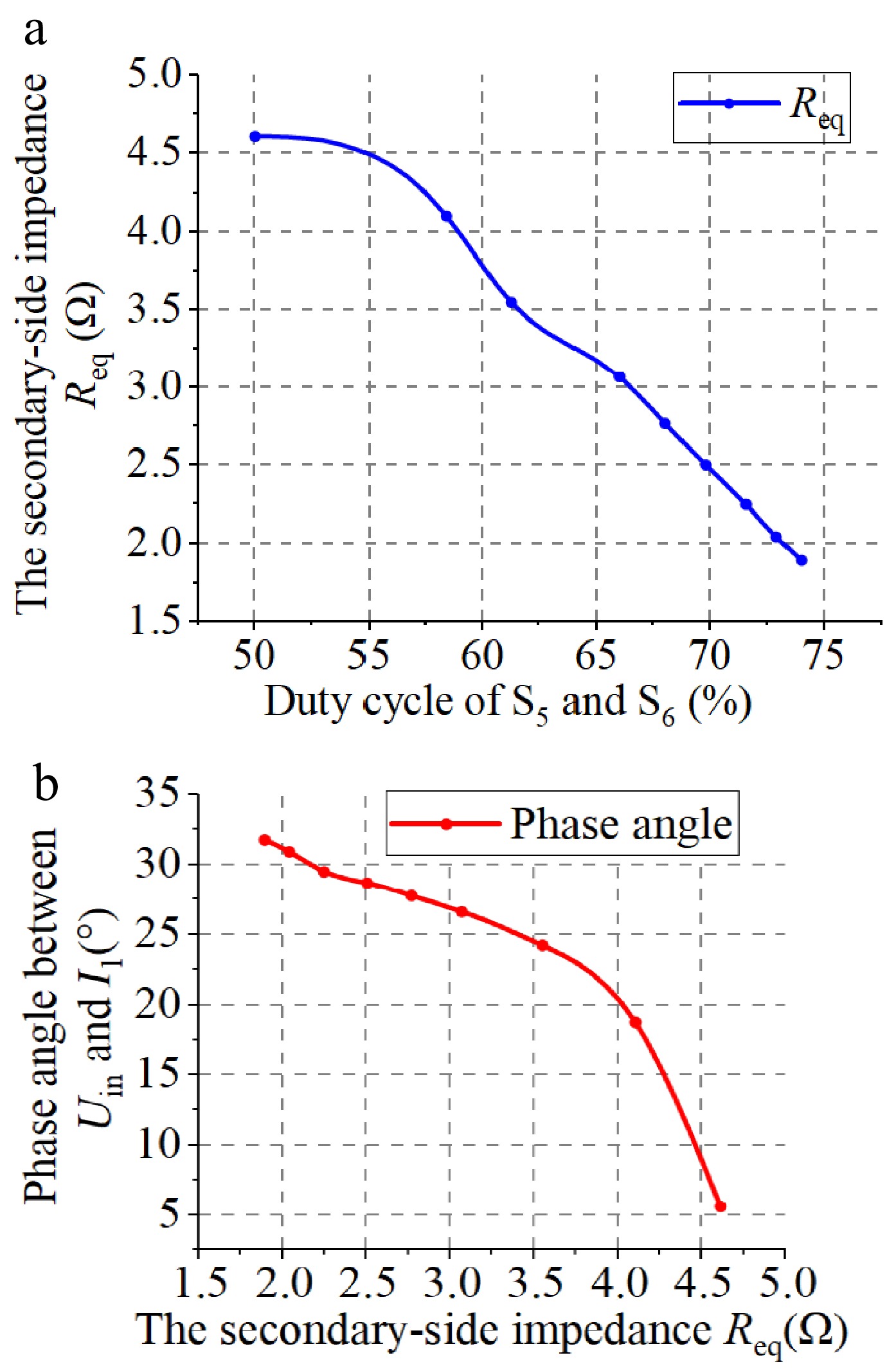
Figure 3.
Secondary-side impedance analysis. (a) Secondary-side impedance vs the duty cycles of S5 and S6. (b) Secondary-side impedance and the phase angle Uin and I1.
-
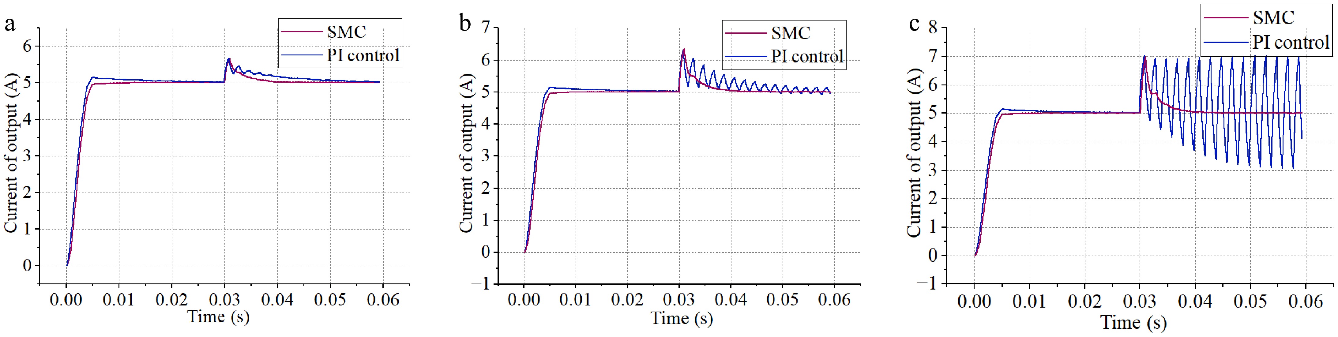
Figure 4.
Comparison of simulation results of SMC and PI control. (a) M suddenly changes to 18.67 μH. (b) M suddenly changes to 21.33 μH. (c) M suddenly changes to 24 μH.
-
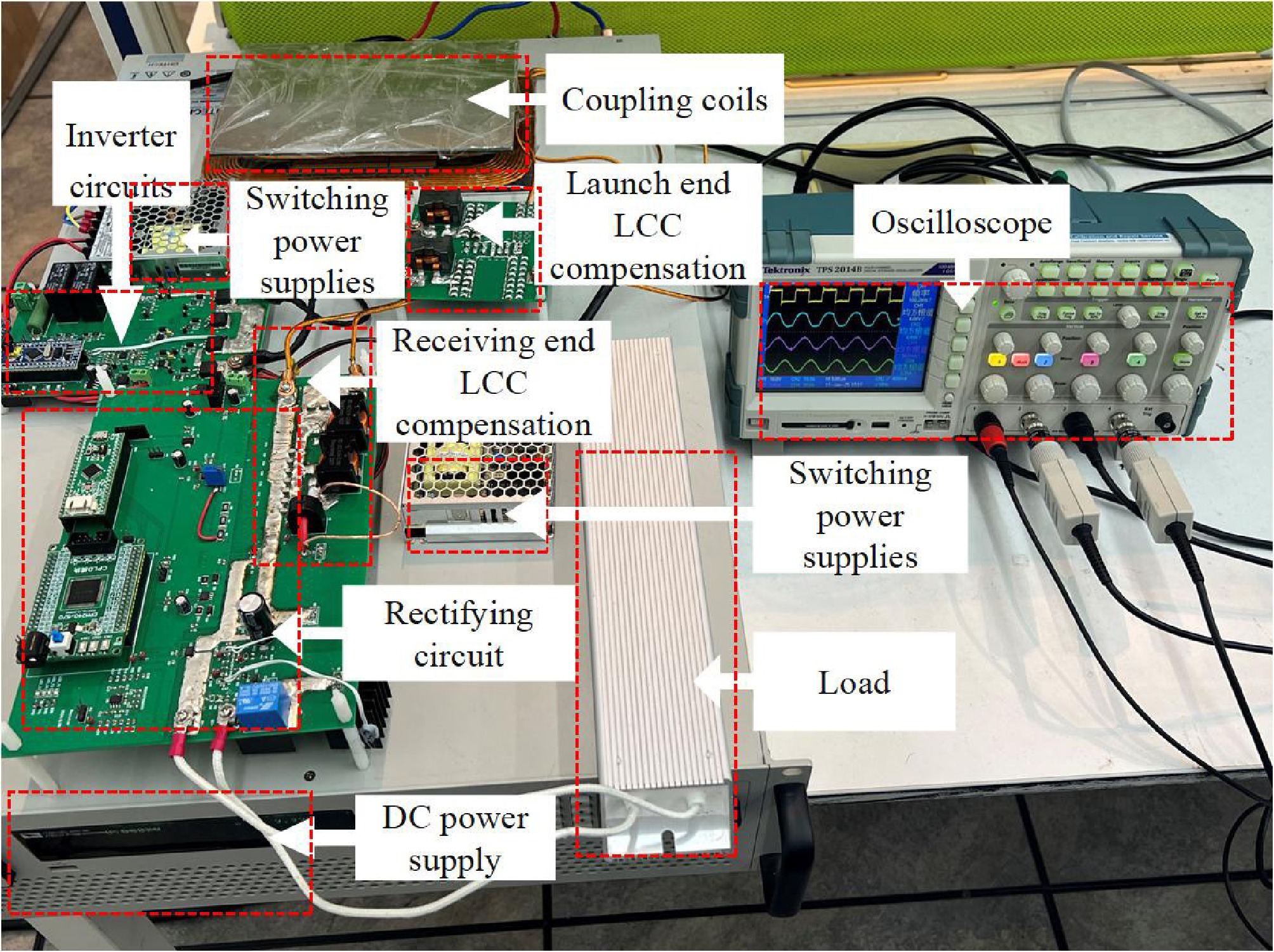
Figure 5.
Experimental prototype.
-
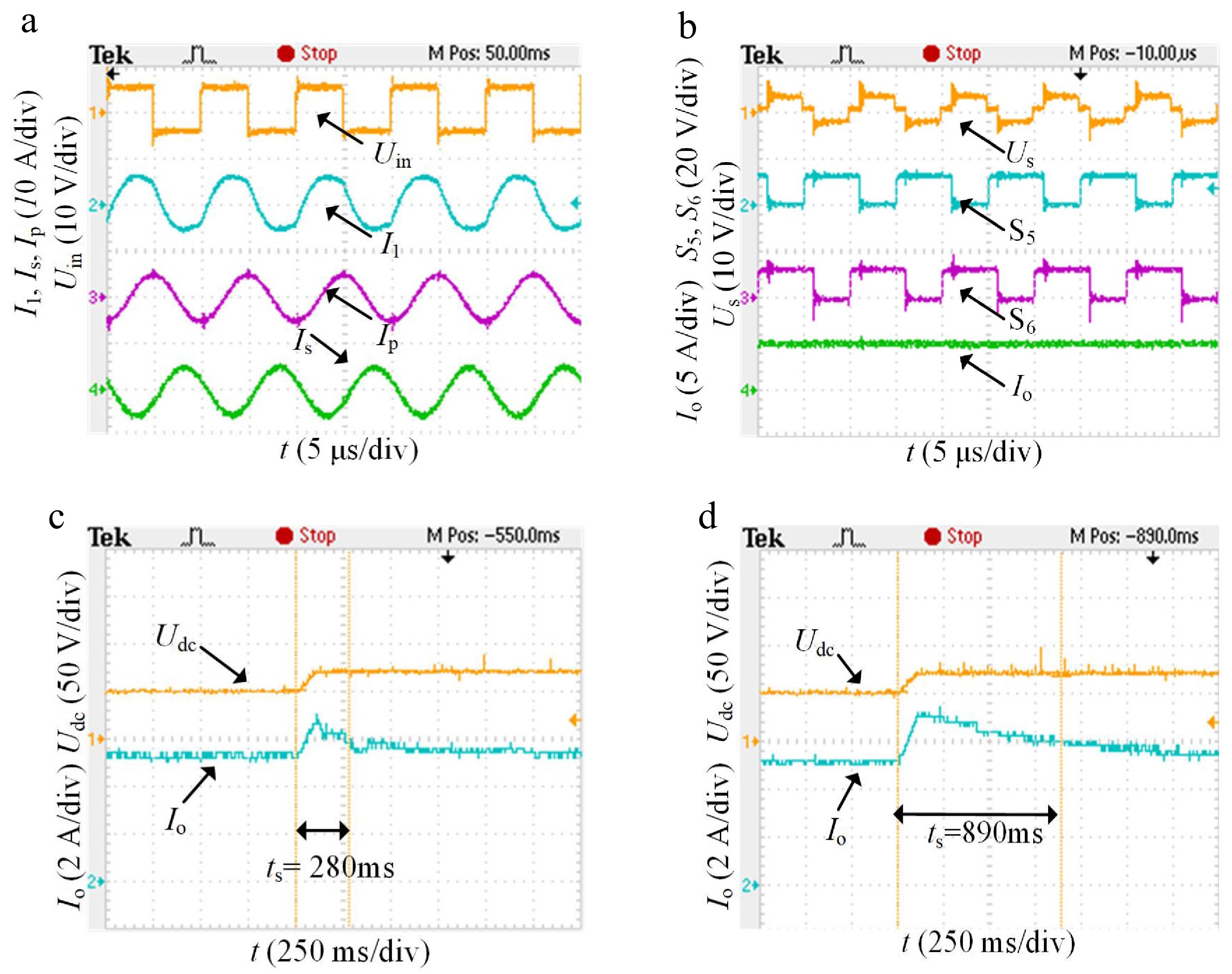
Figure 6.
Experimental waveforms. (a) Inverter output voltage current and coil current. (b) Controllable rectifier.
-
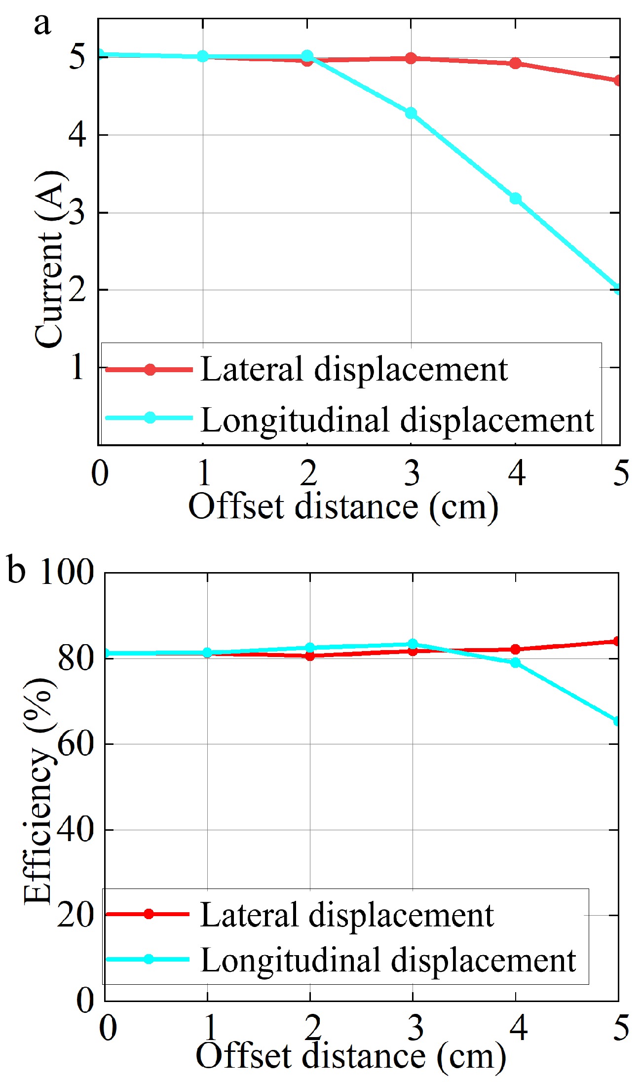
Figure 7.
Offset results. (a) Relation between output current and offset distance. (b) Relation between DC-DC efficiency and offset distance.
-
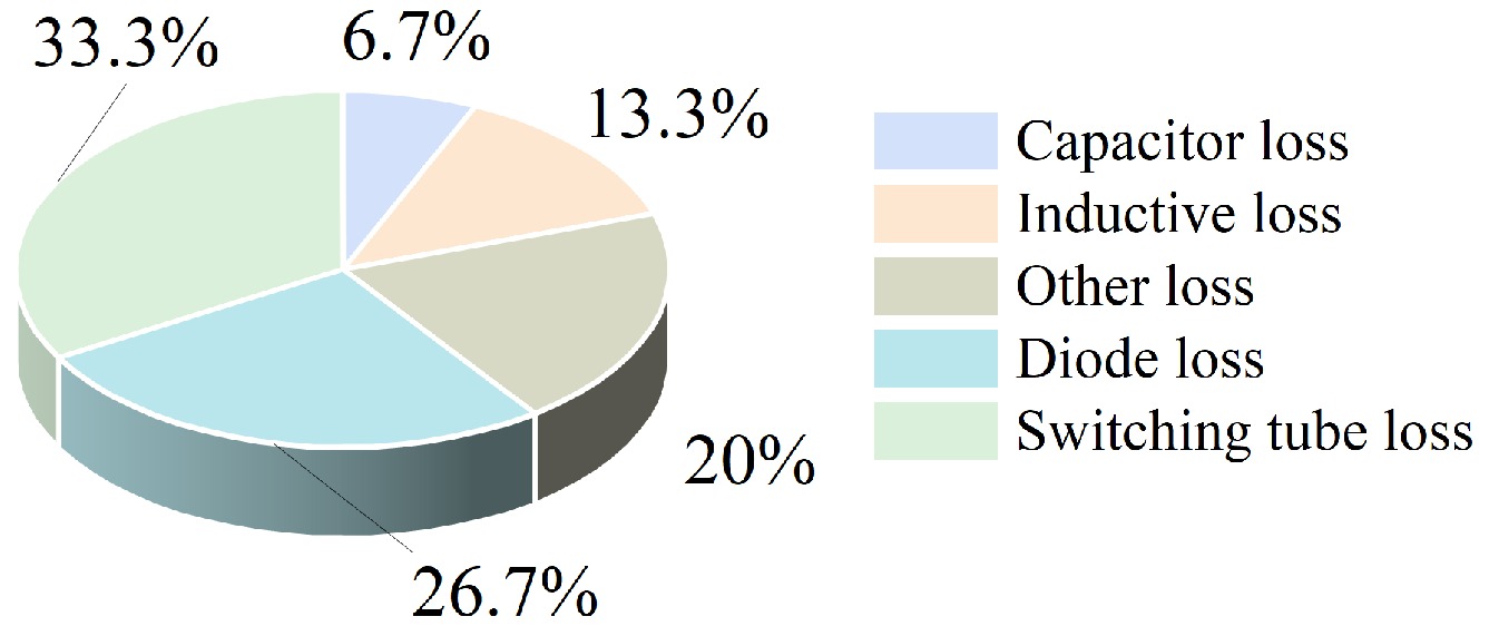
Figure 8.
Power loss ratio of each part of the circuit.
-
Parameters Values Parameters Values Udc 50 V Ls 44.9 μH C1 133.3 nF C4 241.2 nF C2 82.2 nF C5 100 μF L1 19 μH L2 10.5 μH C3 76.8 nF L3 4.7 μH Lp 49.8 μH RL 5.3 Ω Table 1.
System circuit parameters.
-
Table 2.
Comparison with previous controlled circuit topologies.
Figures
(8)
Tables
(2)