


-
In recent years, intensified population aging has amplified the demand for electric wheelchairs among mobility-impaired elderly and disabled individuals. Conventional electric wheelchairs rely on wired charging systems, which pose operational challenges and safety risks for users with limited mobility. Wireless Power Transfer (WPT) technology, recognized for its flexibility, convenience, safety, and reliability, has emerged as an inevitable solution for wheelchair charging[1−5]. However, dynamic postural adjustments (e.g., reaching movements or sudden standing/sitting) induce variable mechanical loads on wheelchairs, causing coupling coil misalignment or distance variations that compromise WPT efficiency and stability[6−8].
The control strategies of typical WPT are primarily categorized into primary-side phase-shift modulation and secondary-side DC-DC regulation. The primary-side approach utilizes phase-shifted full-bridge topology for power transfer adjustment, but necessitates real-time communication modules that escalate system complexity[9−11]. Conversely, the secondary-side methodology employs Buck/Boost converters for voltage regulation, which, while simplifying control architecture, incurs efficiency degradation from supplementary power conversion stages and introduces cost increments[12,13]. Both methodologies exhibit inherent trade-offs among three critical performance metrics: system efficiency, implementation cost, and spatial utilization effectiveness.
The proportional-integral-derivative (PID) algorithm's inherent hysteresis limits adaptability in scenarios demanding rapid dynamic response and disturbance resilience[14]. While model predictive control (MPC) offers superior optimization capabilities, its real-time implementation in high-frequency systems remains constrained by computational complexity[15]. Robust control methods address uncertainties through conservative designs, often resulting in suboptimal dynamic performance[16]. In contrast, sliding-mode-control (SMC) demonstrates superior robustness and transient response characteristics for WPT systems. SMC has been successfully implemented in typical applications within the domain of power electronic converters, exemplified by MOSFET-based voltage stabilization control for post-rectification stage loads, as well as its deployment in voltage regulation strategies for four-phase interleaved parallel boost converters[17,18]. Notably, prior research has scarcely explored the integration of SMC methodologies into rectification stages within WPT systems.
This study proposes a novel wireless charging system integrating controlled rectification with SMC to address interference mitigation in electric wheelchair applications. Distinct from primary-side phase-shift modulation and secondary-side DC-DC regulation, our strategy eliminates auxiliary power conversion stages and cross-coupling communication requirements. The SMC enhanced architecture demonstrates enhanced robustness against dynamic coil displacement while maintaining charging stability through rapid disturbance rejection. Experimental validation confirms the system's operational reliability under variable coupling conditions, establishing a foundation for practical implementation in adaptive wheelchair charging scenarios.
-
Figure 1a shows the schematic of the electric wheelchair's wireless charging system, with a transmitting coil embedded in the power supply base and a receiving coil on the wheelchair chassis. Due to the inherent constant-current characteristics of both the transmitting coil and output, the dual-side LCC resonant topology is adopted in this study. As illustrated in Fig. 1b, the system employs a dual-side LCC resonant compensation topology featuring primary-side coil current (Ip), and secondary-side loop current (I2) stabilization through coordinated resonant networks. A full-bridge inverter (S1−S4) converts DC input (Udc) to high-frequency AC excitation, feeding the primary resonant network comprising series inductance L1, parallel capacitance C1, and series capacitance C2. Magnetically coupled coils (Lp/Ls, mutual inductance M) interface with the secondary network containing series capacitance C3, parallel capacitance C4, and series inductance L2. Output regulation is achieved through an active rectifier (D1, D2, S5, S6) with post-filtering (L3, C5) to deliver stabilized DC to load RL. Power regulation is achieved through synchronized switching control of S5 and S6.
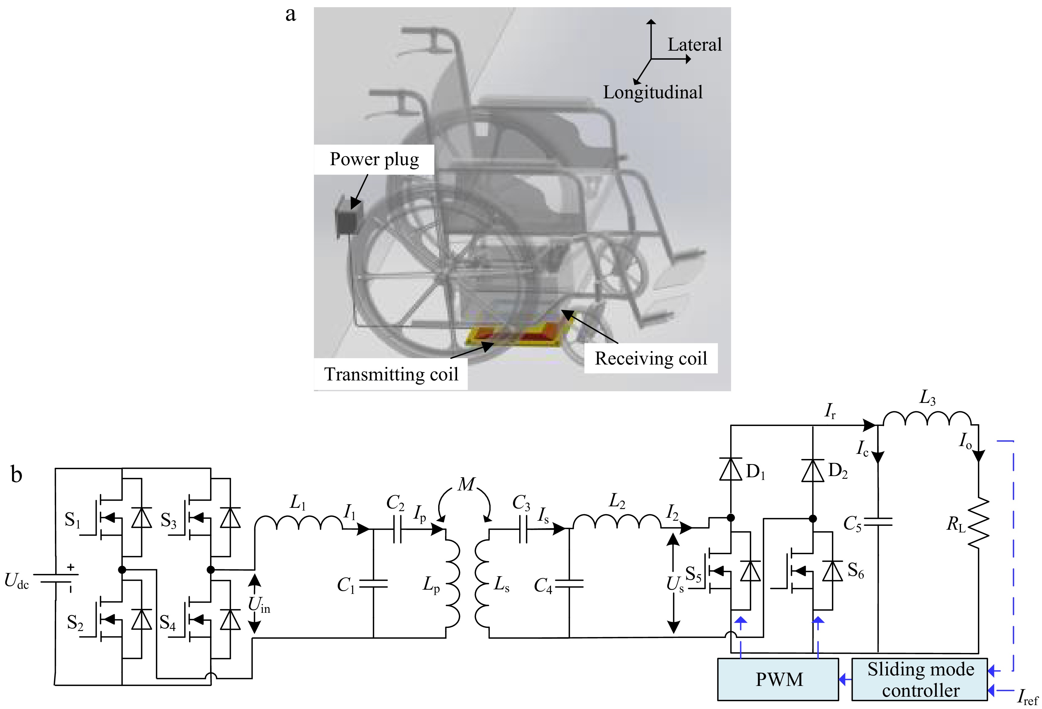
Figure 1.
Wireless charging frame for electric wheelchairs. (a) Wireless charging model. (b) The WPT system with dual-side LCC resonant compensation network.
Topology analysis of dual-side LCC compensation
-
The resonance relation of the system can be expressed as:
$ {\omega _0} = 2{\text π} {f_0} = \dfrac{1}{{\sqrt {{L_1}{C_1}} }} = \dfrac{1}{{\sqrt {{L_2}{C_4}} }} = \dfrac{1}{{\sqrt {{C_2}\left( {{L_{\text{p}}} - {L_1}} \right)} }} = \dfrac{1}{{\sqrt {{C_3}\left( {{L_{\text{s}}} - {L_2}} \right)} }} $ (1) where, f0 is the operating frequency of the system, and ω0 is the angular frequency of the system.
The input voltage Udc is converted by the inverter to output a square-wave voltage, and the amplitude Uin of its fundamental component is as:
$ \left| {{{\mathbf{U}}_{{\mathbf{in}}}}} \right| = \dfrac{{{\text{2}}\sqrt 2 {U_{{\text{dc}}}}}}{{\text{π }}} $ (2) It can be obtained from the KVL equation of the primary side as:
$ {{\mathbf{U}}_{{\mathbf{in}}}} = j{\omega _0}{L_1}{{\mathbf{I}}_{\mathbf{1}}} + \dfrac{1}{{j{\omega _0}{C_1}}}\left( {{{\mathbf{I}}_{\mathbf{1}}} - {{\mathbf{I}}_{\mathbf{p}}}} \right) $ (3) The current Ip of the transmitting coil can be calculated from Eqs (1) and (3) as:
$ {{\mathbf{I}}_{\mathbf{p}}} = \dfrac{{{{\mathbf{U}}_{{\mathbf{in}}}}}}{{j{\omega _0}{L_1}}} $ (4) It can be obtained from the KVL equation of the secondary side as:
$ j{\omega _0}M{{\mathbf{I}}_{\mathbf{p}}} = \left( {j{\omega _0}{L_{\text{s}}} + \dfrac{1}{{j{\omega _0}{C_3}}}} \right){{\mathbf{I}}_{\mathbf{s}}} + \left( {{{\mathbf{I}}_{\mathbf{s}}} - {{\mathbf{I}}_{\mathbf{2}}}} \right)\dfrac{1}{{j{\omega _0}{C_4}}} $ (5) From Eqs (1) and (5), the rectified input current I2 can be calculated as:
$ {{\mathbf{I}}_{\mathbf{2}}} = \dfrac{{jM{{\mathbf{I}}_{\mathbf{p}}}}}{{{L_2}}} $ (6) According to Eqs (2), (4), and (6), it can be obtained as:
$ \left| {{{\mathbf{I}}_{\mathbf{2}}}} \right| = \dfrac{{{\text{2}}\sqrt 2 {U_{{\text{dc}}}}M}}{{{\omega _0}{L_1}{L_2}{\text{π }}}} $ (7) According to Eq. (7), the rectified input current I2 is independent of the load, so it has a constant current output characteristic.
Mode analysis of controlled rectifier operation
-
In terms of the rectifier part circuit, the duty cycle of S5 and S6 is adjusted to achieve the goal of controllable rectification. As shown in Fig. 2a, the switching state of the S5/S6 in each cycle can be divided into four modes. 2a represents the pulse width in one cycle when the S5 is on and the S6 is on. Since a is always greater than or equal to 0, the duty cycle range of S5 and S6 is 50% to 100%.
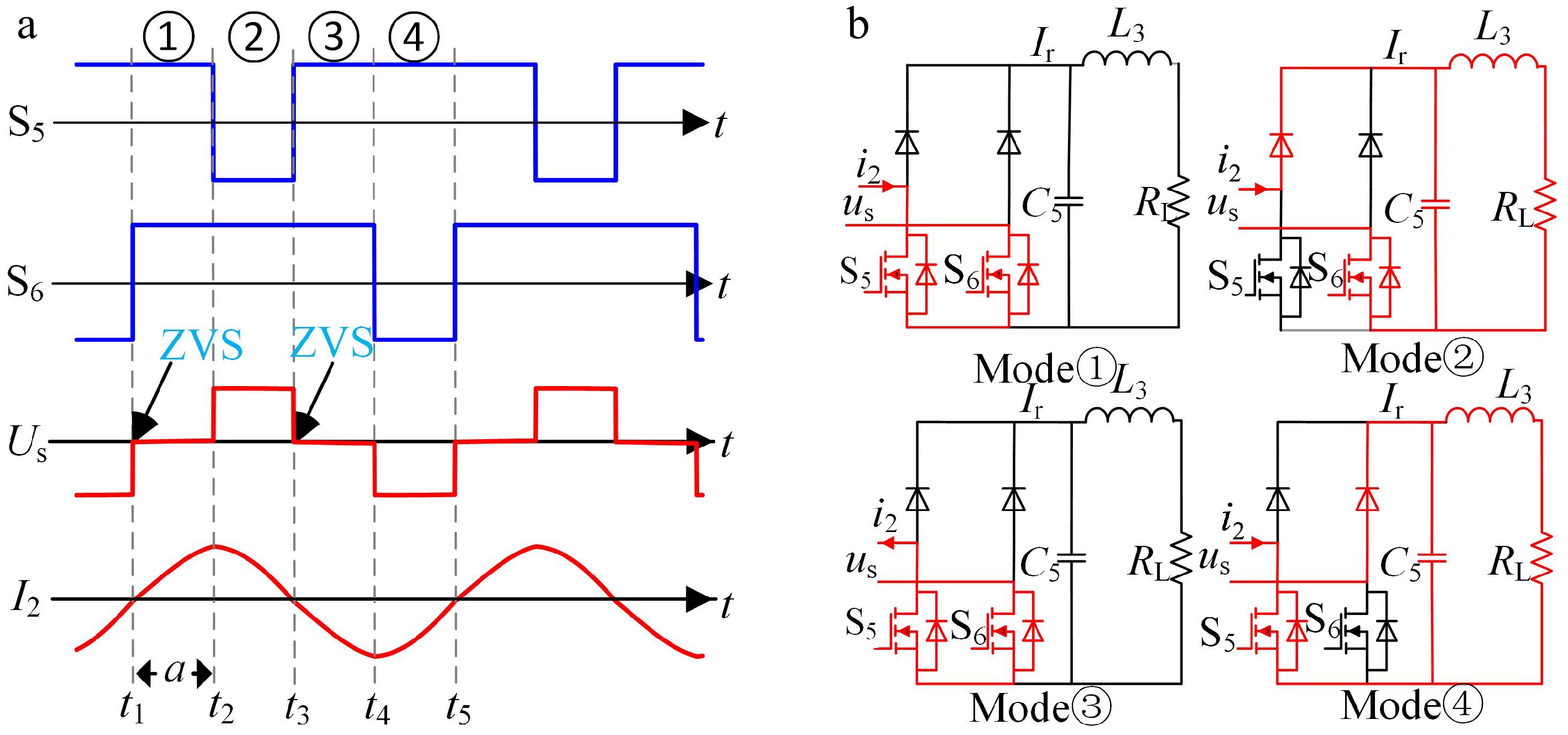
Figure 2.
Mode analysis of controlled rectifier operation. (a) Pulse phase difference of the rectifier. (b) Modal circuit analysis.
The mode of operation of each mode is shown in Fig. 2b, where i2 represents the instantaneous value of I2.
Mode ①: From t1 to t2, S5 is conducting at a high level, and S6 is also conducting at a high level. Since S5 and S6 are both conducting simultaneously, it results in a direct short circuit, and Ir equals 0. The dual-side LCC exhibits an electrically isolated state towards the load.
Mode ②: From t2 to t3, S5 is turned off (low level), and S6 remains conducting at a high level. The rectifier input current is I2. At this stage, Ir = I2 and the dual LCC circuit operates in a charging state towards the load.
Mode ③: From t3 to t4, S5 is conducting at a high level, and S6 is also conducting at a high level. The simultaneous conduction of S5 and S6 causes a direct short circuit, resulting in Ir being 0. The dual-side LCC again exhibits an electrically isolated state towards the load.
Mode ④: From t4 to t5, S5 is conducting at a high level, and S6 is turned off (low level). The rectifier input current remains I2. At this stage, Ir = −I2 and the dual-side LCC circuit operates in a charging state towards the load.
By dynamically adjusting the duty cycle of S5 and S6, the load charging cycle ratio can be precisely controlled, enabling current closed-loop regulation. Notably, the topology achieves Zero Voltage Switching (ZVS) in Modal ① and Modal ③ through a comparator-based zero-crossing detection circuit. This technique not only eliminates the voltage-current overlap losses associated with traditional hard switching but also recovers energy stored in the parasitic capacitance via resonance.
When a controlled rectifier is employed, the impedance characteristic of the secondary side transitions from purely resistive to a dynamically tunable complex impedance. To investigate system behavior under varying mutual inductance coefficients between the coils, simulations were conducted. To maintain a stable output current of 5 A, the duty cycles of switches S5/S6 in the controlled rectifier must be dynamically adjusted in response to changes in mutual inductance. As shown in Fig. 3a, experimental results reveal a negative correlation between the secondary-side impedance (Req) and the duty cycles of S5/S6.
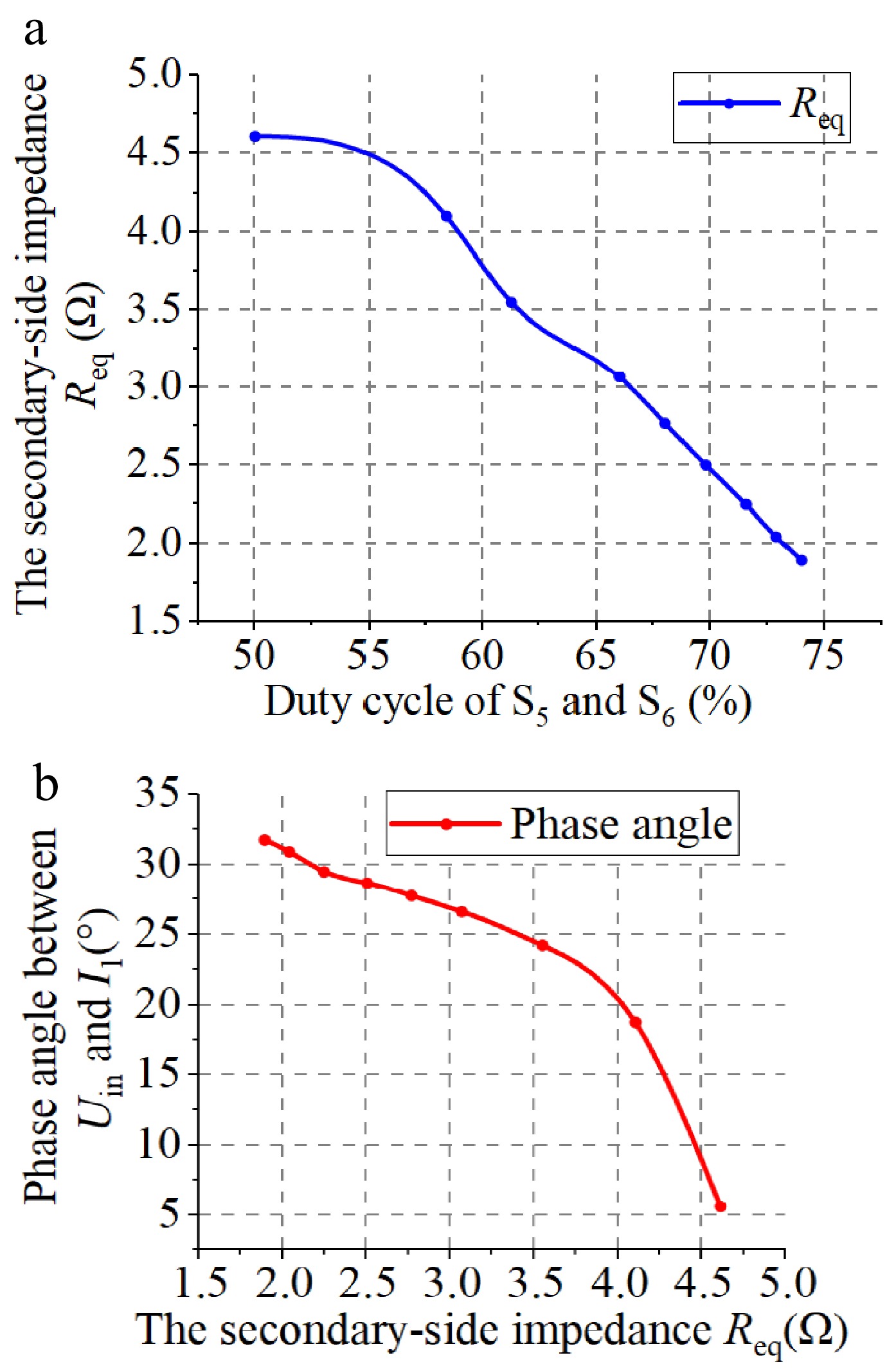
Figure 3.
Secondary-side impedance analysis. (a) Secondary-side impedance vs the duty cycles of S5 and S6. (b) Secondary-side impedance and the phase angle Uin and I1.
Variations in secondary-side impedance may potentially influence the ZVS performance of the system. To assess this, the phase difference between the inverter input voltage Uin and current I1 is monitored. As illustrated in Fig. 3b, this phase difference also shows a negative correlation with the secondary-side impedance and consistently remains no less than 5.1°. The results show that the inverter output voltage phase leads the output current, resulting in an inductive load characteristic. This inductive behavior facilitates the achievement of ZVS in the system under normal operating conditions.
The rectifier bridge output current Ir can be expressed as:
$ {I_{\text{r}}} = \left| {{{\mathbf{I}}_{\mathbf{2}}}} \right|\cos \dfrac{a}{2} = \dfrac{{{\text{2}}\sqrt 2 {U_{{\text{dc}}}}M}}{{{\text{π }}{\omega _0}{L_1}{L_2}}}\cos \dfrac{a}{2} $ (8) The state space representation of the output current Io can be formulated as:
$ \left[ \begin{gathered} \dfrac{{d{I_{\text{o}}}}}{{dt}} \\ \dfrac{{{d^2}{I_{\text{o}}}}}{{d{t^2}}} \\ \end{gathered} \right] = \left[ {\begin{array}{*{20}{c}} 0&1 \\ { - \dfrac{1}{{{C_5}{L_3}}}}&{ - \dfrac{{{R_{\text{L}}}}}{{{L_3}}}} \end{array}} \right]\left[ {\begin{array}{*{20}{c}} {{I_{\text{o}}}} \\ {\dfrac{{d{I_{\text{o}}}}}{{dt}}} \end{array}} \right] + \left[ {\begin{array}{*{20}{c}} 0 \\ {\dfrac{{{I_{\text{r}}}}}{{{C_5}{L_3}}}} \end{array}} \right] $ (9) As derived from Eqs (8) and (9), the output current Io can be regulated through the implementation of a controlled rectification strategy.
-
To achieve Io tracking to the reference current (Iref), this study uses the tracking deviation as a state variable. The tracking deviation x1, its rate of change x2, and its integral x3 are defined as:
To achieve Io tracking to the reference current (Iref), this study uses the tracking deviation as a state variable. The tracking deviation x1, its rate of change x2, and its integral x3 are defined as:
$ \left[ {\begin{array}{*{20}{c}} {{x_1}} \\ {{x_2}} \\ {{x_3}} \end{array}} \right] = \left[ {\begin{array}{*{20}{c}} {{I_{{\text{ref}}}} - {I_0}} \\ {\dfrac{{d\left( {{I_{{\text{ref}}}} - {I_0}} \right)}}{{dt}}} \\ {\int {\left( {{I_{{\text{ref}}}} - {I_0}} \right)dt} } \end{array}} \right] $ (10) The control input u is defined to satisfy the following conditions:
$ \left\{ {\begin{array}{*{20}{l}} {{I_{\text{r}}} = \dfrac{{{\text{2}}\sqrt 2 {U_{{\text{dc}}}}M}}{{{\text{π }}{\omega _0}{L_1}{L_2}}}\cos \dfrac{a}{2} = \left| {{{\mathbf{I}}_{\mathbf{2}}}} \right|u} \\ {u \in \left[ {0,1} \right]} \end{array}} \right. $ (11) Therefore, according to Eq. (11), the following control state equation can be listed:
$ \left[ \begin{gathered} \dfrac{{d{x_1}}}{{dt}} \\ \dfrac{{d{x_2}}}{{dt}} \\ \dfrac{{d{x_3}}}{{dt}} \\ \end{gathered} \right] = \left[ {\begin{array}{*{20}{c}} 0&1&0 \\ 0&{ - \dfrac{{{R_L}}}{{{L_3}}}}&0 \\ 1&0&0 \end{array}} \right]\left[ {\begin{array}{*{20}{c}} {{x_1}} \\ {{x_2}} \\ {{x_3}} \end{array}} \right] + \left[ {\begin{array}{*{20}{c}} 0 \\ {\dfrac{{\left| {{{\mathbf{I}}_{\mathbf{2}}}} \right|}}{{{C_5}{L_3}}}} \\ 0 \end{array}} \right]u + \left[ {\begin{array}{*{20}{c}} 0 \\ {\dfrac{{{I_{\text{o}}}}}{{{C_5}{L_3}}}} \\ 0 \end{array}} \right] $ (12) The sliding mode plane is designed as:
$ s = {x_1} + {c_2}{x_2} + {c_3}{x_3} $ (13) Thus, the following equation holds:
$ \dfrac{{ds}}{{dt}} = - \dfrac{{d{I_{\text{o}}}}}{{dt}} - {c_2}\dfrac{{{d^2}{I_{\text{o}}}}}{{d{t^2}}} + {c_3}\left( {{I_{{\text{ref}}}} - {I_o}} \right) $ (14) The power-law reaching law has significant advantages in reducing chattering, accelerating convergence, and improving robustness[19]. Therefore, this paper adopts the power-law reaching law, leading to the following as:
$ \dfrac{{ds}}{{dt}} = - k{\left| s \right|^r}{sgn} \left( s \right),0 \lt r \lt 1 $ (15) Thus, the control input u is obtained as:
$ \begin{split}u =\;& - \dfrac{{{C_5}{L_3}}}{{{c_2}\left| {{{\mathbf{I}}_{\mathbf{2}}}} \right|}}k{\left| s \right|^r}{sgn} \left( s \right) + \left( { - \dfrac{{{C_5}{L_3}}}{{{c_2}\left| {{{\mathbf{I}}_{\mathbf{2}}}} \right|}} + \dfrac{{{C_5}{R_L}}}{{\left| {{{\mathbf{I}}_{\mathbf{2}}}} \right|}}} \right)\dfrac{{d{I_{\text{o}}}}}{{dt}} +\\& \left( {\dfrac{1}{{\left| {{{\mathbf{I}}_{\mathbf{2}}}} \right|}} - \dfrac{{{c_3}{C_5}{L_3}}}{{{c_2}{I_2}}}} \right){I_{\text{o}}} + \dfrac{{{c_3}{C_5}{L_3}}}{{{c_2}\left| {{{\mathbf{I}}_{\mathbf{2}}}} \right|}}{I_{{\text{ref}}}} \end{split}$ (16) The PWM duty cycle 2a for driving S5 and S6 can be obtained from Eq. (11) based on the control input u, thereby regulating the output current Io.
-
To validate the correctness of the theoretical analysis and control methodology presented in this paper, a simulation model of the dual-LCC topology circuit diagram illustrated in Fig. 1a was established in MATLAB/Simulink. The simulation parameters correspond to those specified in Table 1 of the experimental section. The system frequency f0 was maintained at 100 kHz by controlling S5/S6 in the inverter, fulfilling Eq. (1) for constant-current WPT operation. The output current Io sampling frequency was set to 1 kHz.
Table 1. System circuit parameters.
Parameters Values Parameters Values Udc 50 V Ls 44.9 μH C1 133.3 nF C4 241.2 nF C2 82.2 nF C5 100 μF L1 19 μH L2 10.5 μH C3 76.8 nF L3 4.7 μH Lp 49.8 μH RL 5.3 Ω For electric wheelchair wireless charging simulations, practical complexities were considered: Mutual inductance between coils varies dynamically. With Iref = 5 A and initial M = 16 μH, abrupt M increases at specific times were simulated to mimic real-world conditions.
The simulation results of the WPT system using SMC are shown in Fig. 4. In Fig. 4a, when M suddenly shifts to 18.67 μH with an initial value of 16 μH, the SMC enables the system to reach a stable state rapidly with a minimal steady-state error. In contrast, the PI control, though achieving stability eventually, takes much longer. At 0.03 s, with M at 18.67 μH, SMC outperforms PI control in restoring system stability faster, driving the output current close to 5 A. Fig. 4 depicts the scenario where the M changes to 21.33 μH at 0.03 s from 16 μH. SMC prompts a quick response, achieving system convergence and stable operation promptly, with a precisely controlled low steady-state error. Conversely, PI control has a sluggish adjustment, taking more time to reduce deviations and leaving a significant steady-state error. In Fig. 4c, when M jumps from 16 to 24 μH at 0.03 s, SMC swiftly converges to the steady-state error and stabilizes the system. However, PI control shows instability, with the steady-state error diverging and deviating from the expected value.
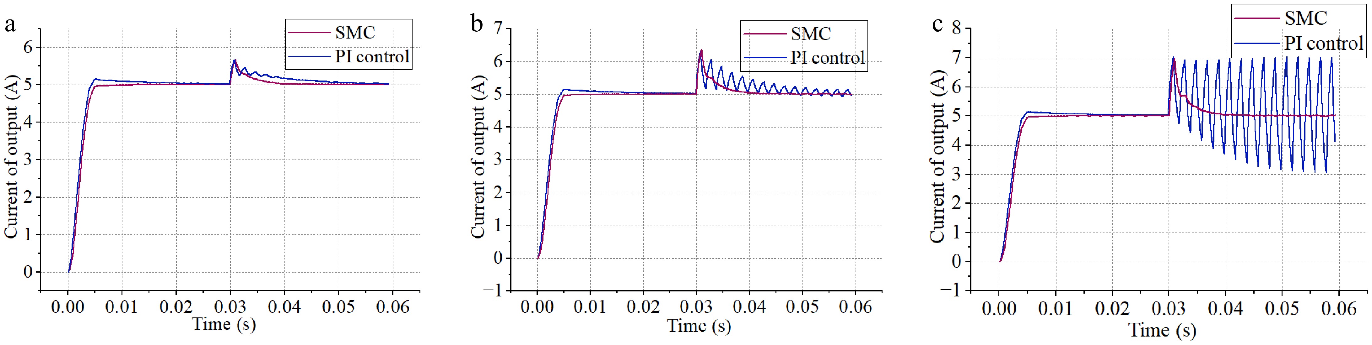
Figure 4.
Comparison of simulation results of SMC and PI control. (a) M suddenly changes to 18.67 μH. (b) M suddenly changes to 21.33 μH. (c) M suddenly changes to 24 μH.
The simulation results demonstrate that SMC outperforms PI control in electric wheelchair wireless charging systems. SMC achieves faster stabilization and shorter disturbance-induced instability periods. Its superior disturbance rejection ensures stable charging processes under significant coupling coefficient perturbations, maintaining minimal steady-state deviations.
-
The experimental setup of the electric wheelchair wireless charging system is shown in Fig. 5, and the experimental circuit parameters are shown in Table 1.
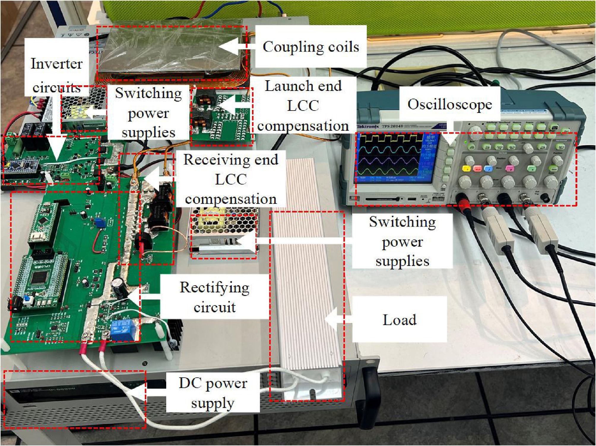
Figure 5.
Experimental prototype.
At the transmitter side, the DC power is converted to high-frequency AC by a full-bridge inverter, operating at a frequency of 100 kHz. At the receiver side, the system uses a CPLD to adjust the duty cycle of two MOSFETs via a driver chip, to regulate the load current of the rectifier bridge. The system is designed with a target output current Iref of 5 A to charge a 24 V, 10 Ah lead-acid battery pack, with an approximate charging duration of 2 h.
Experimental results
-
The corresponding operational waveforms are presented in Fig. 6. In Fig. 6a, the inverter output current I1 lags the voltage Uin, indicating an inductive system that supports ZVS. The RMS currents for the transmitter and receiver coils are 3.62 and 3.75 A, respectively. In Fig. 6b, the rectifier input voltage includes zero-voltage periods within each cycle. When switches S5 and S6 conduct synchronously, the rectifier enters a short-circuit regulation mode, where the output current is dynamically controlled to 5 A by adjusting the conduction duration of S5 and S6.
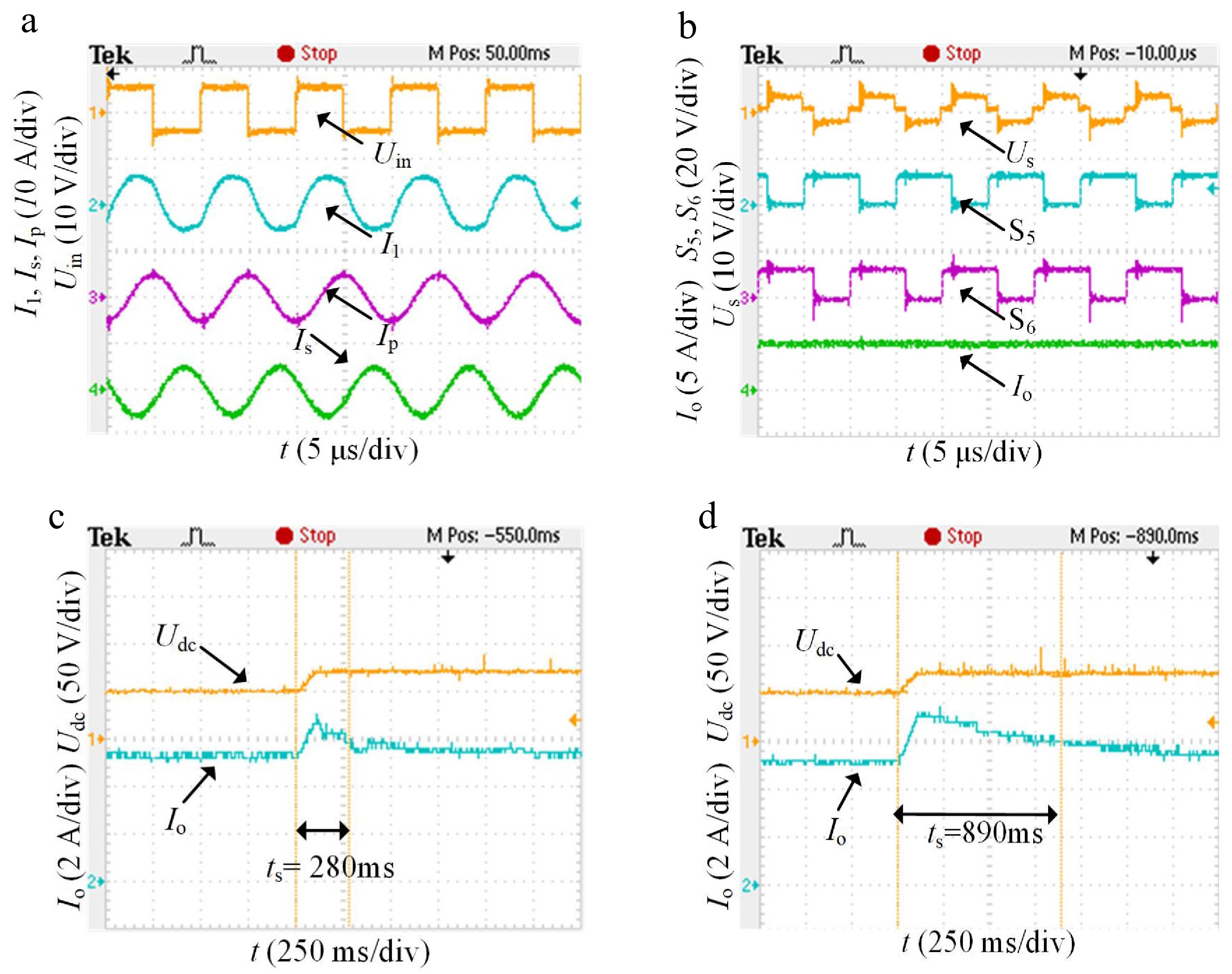
Figure 6.
Experimental waveforms. (a) Inverter output voltage current and coil current. (b) Controllable rectifier.
After the system stabilizes, the DC input voltage Udc increases from 50 to 70 V, simulating a sudden decrease in coil spacing during wireless charging for an electric wheelchair, leading to a 40% increase in the mutual inductance coupling coefficient. Due to the difficulty in precisely controlling the coil spacing and the susceptibility of the experiment to environmental interference, accurately adjusting the coupling coefficient between coils presents significant challenges and potential safety risks. According to Eq. (8), both the mutual inductance M and input voltage Udc have the same linear effect on the Ir. Therefore, increasing Udc to emulate the effect of enhanced magnetic coupling resulting from reduced coil spacing is an effective and safer experimental approach. The performance of PI control and SMC is compared in Fig. 6c, d. SMC significantly outperforms PI control in both dynamic response and steady-state accuracy. Specifically, SMC reduces the settling time to 280 ms (68.6% faster than PI control) and achieves a steady-state error of 80 mA (68% less than PI control), while PI control has a settling time of 890 ms and a steady-state error of 250 mA. The results show that SMC, with its variable structure, ensures fast response and minimizes steady-state fluctuations, demonstrating superior robustness and precision.
Offset analysis
-
Figure 7a shows that the system maintains a 5 A charging current when the lateral offset is less than 4 cm or the longitudinal offset is less than 2 cm. Beyond these critical values, the charging current decreases. Fig. 7b illustrates the DC-DC efficiency as a function of offset distance, which remains above 80% within a 3 cm lateral or longitudinal offset range. Within the controllable offset range, system efficiency increases as the coil offset grows. This occurs because the reduced lateral offset shortens the conduction time of the short-circuit loop formed by S5 and S6, thereby reducing reactive power circulation and associated losses, such as switch conduction losses and inductor copper losses, when no power is delivered to the load, ultimately improving system efficiency. However, the resonant inductor adopted in this system has an extremely low internal resistance of approximately 7 mΩ, and the on-resistance of the power switching transistors is also very low at 89 mΩ. Therefore, the conduction of S5 and S6 has a minimal impact on the system efficiency. When the offset exceeds the controllable range, the system enters an abnormal state, causing the load current to drop below the critical value and sharply reduce efficiency.
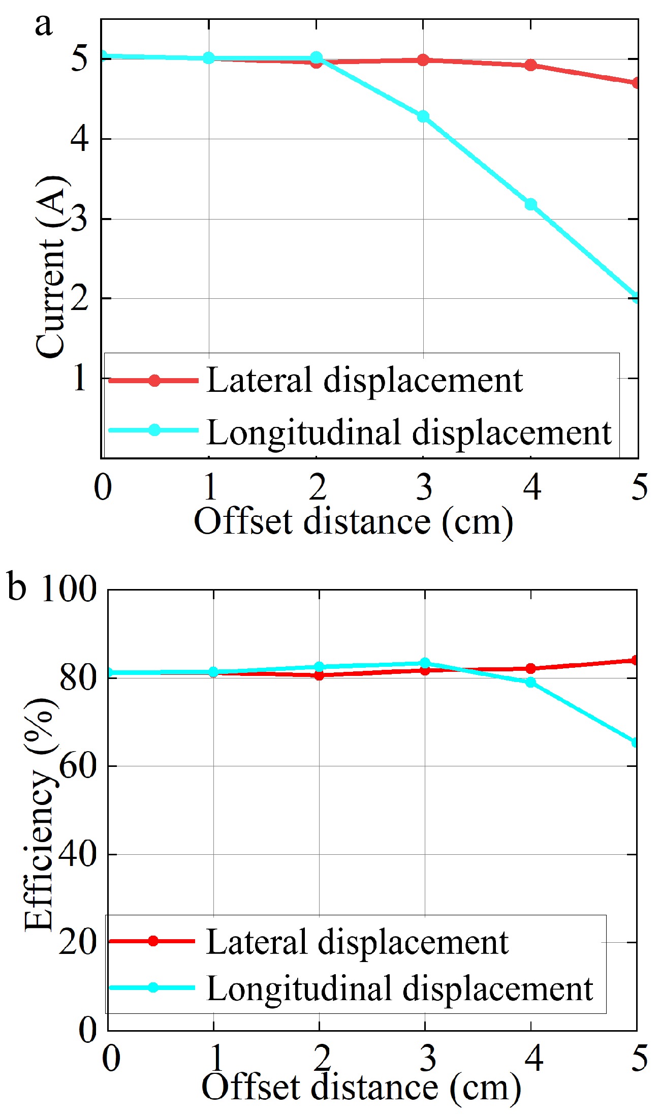
Figure 7.
Offset results. (a) Relation between output current and offset distance. (b) Relation between DC-DC efficiency and offset distance.
In summary, the magnetic coupler can maintain a rated 5 A charging current when the lateral offset is less than 4 cm or the longitudinal offset is less than 2 cm, with the DC-DC efficiency remaining above 80%. The 27 W total system power loss at 135 W output originates from conduction/switching losses in power switching tubes, forward voltage drops in diodes, inductive winding/core dissipation, capacitor ESR parasitic, and other power losses (line impedance-induced auxiliary losses). Loss distribution proportions are detailed in Fig. 8.
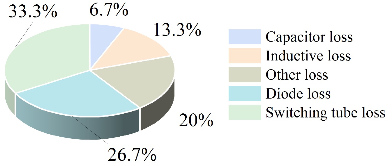
Figure 8.
Power loss ratio of each part of the circuit.
Comparison with previous wireless charging systems
-
As detailed in Table 2, compared to communication-dependent topologies such as the phase-shifted full-bridge inverter[20], primary-side DC-DC converter[22], and dual-side phase-shift control[23], the controlled rectifier scheme proposed in this work does not require a communication link. Therefore, the proposed system can simplify system design and control strategies, reduce implementation complexity and communication costs, and improve overall reliability and scalability.
Table 2. Comparison with previous controlled circuit topologies.
In contrast, while the secondary-side DC-DC converter structure also operates communication-free, it utilizes three converters[21]. The proposed method achieves comparable system performance using only two converters, thereby reducing hardware requirements and improving system integration and cost-effectiveness. In summary, the proposed topology offers distinct advantages in communication-free operation, minimal converter count, and simplified control.
-
This study develops a wireless charging system for electric wheelchairs using controllable rectification and SMC to maintain constant-current output under coupling coil misalignment or distance variations caused by dynamic user behavior. Experimental validation shows SMC reduces regulation time by 68% (280 ms vs 890 ms) vs PI control under 40% coupling coefficient step changes, demonstrating enhanced robustness and dynamic response.
The key innovations of this work include a controllable rectification strategy that simplifies the system topology while reducing energy loss and eliminating communication requirements between primary and secondary sides, along with a sliding mode control approach that offers robust disturbance rejection and rapid dynamic response to ensure system stability and quick adaptation to operational variations.
This study proposes a sliding-mode-controlled rectification method to address coupling coil misalignment or distance variations challenges in wireless charging systems for electric wheelchairs. The methodology demonstrates industrial potential for assistive mobility devices and extends applicability to automotive and UAV charging systems.
This work was supported in part by the National Natural Science Foundation of China (Grant No. 52307004), in part by the Chongqing Natural Science Foundation (Grant No. CSTB2024NSCQ-MSX0667), and in part by the Municipal Education Commission Science and Technology Research Plan Project of Chongqing (Grant No. KJQN202500615).
-
The authors confirm their contributions to the paper as follows: study conception and design: Feng T, Yang J; experimental setup construction: Zhang J, Ren Y, Yang J; draft manuscript preparation: Yang J, Feng T, Tang L. All authors reviewed the results and approved the final version of the manuscript.
-
The data that support the findings of this study are available from the corresponding author upon reasonable request.
-
The authors declare that they have no conflict of interest.
- Copyright: © 2025 by the author(s). Published by Maximum Academic Press, Fayetteville, GA. This article is an open access article distributed under Creative Commons Attribution License (CC BY 4.0), visit https://creativecommons.org/licenses/by/4.0/.
-
About this article
Cite this article
Yang J, Feng T, Zhang J, Ren Y, Tang L. 2025. A sliding-mode-controlled rectification method for electric wheelchair wireless charging. Wireless Power Transfer 12: e026 doi: 10.48130/wpt-0025-0025 

A sliding-mode-controlled rectification method for electric wheelchair wireless charging
- Received: 11 April 2025
- Revised: 01 June 2025
- Accepted: 09 July 2025
- Published online: 29 September 2025
Abstract: This article proposes a sliding-mode-controlled rectification method to address charging current fluctuations caused by coupling coil misalignment or distance variations in electric wheelchair applications. Firstly, a circuit model is established based on a dual-side inductor-capacitor-capacitor (LCC) resonant compensation network, elucidating the constant-current characteristics of the rectifier input. Subsequently, the operational modes of controllable rectification are analyzed to demonstrate the feasibility of closed-loop control. A sliding-mode-control-based constant-current output control strategy is then proposed and mathematically modeled. Simulation results show that sliding mode control (SMC) is significantly superior to proportional-integral (PI) control. Finally, a 135 W-level experimental platform for electric wheelchair wireless charging is constructed. Comparative experiments between SMC and traditional PI control reveal that when the mutual inductance coefficient disturbance increases by 40%, both control methods maintain 5 A current output, but the SMC reduces adjustment time by approximately 68%. Experimental results verify that the proposed sliding-mode-controlled rectification system for electric wheelchair wireless charging exhibits enhanced robustness and rapid dynamic response characteristics.