-
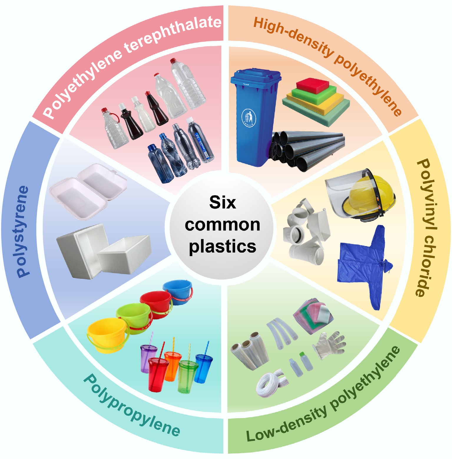
Figure 1.
Basic structure and product diagram of six common polymers (HDPE, LDPE, PP, PS, PVC, and PET).
-
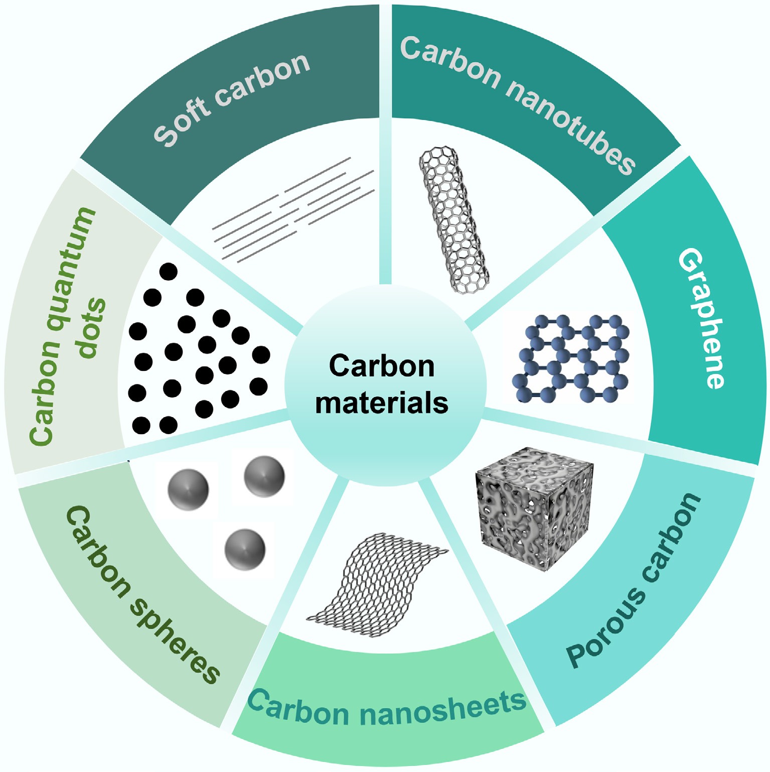
Figure 2.
Seven types of functional carbon materials derived from the carbonization of plastic waste.
-
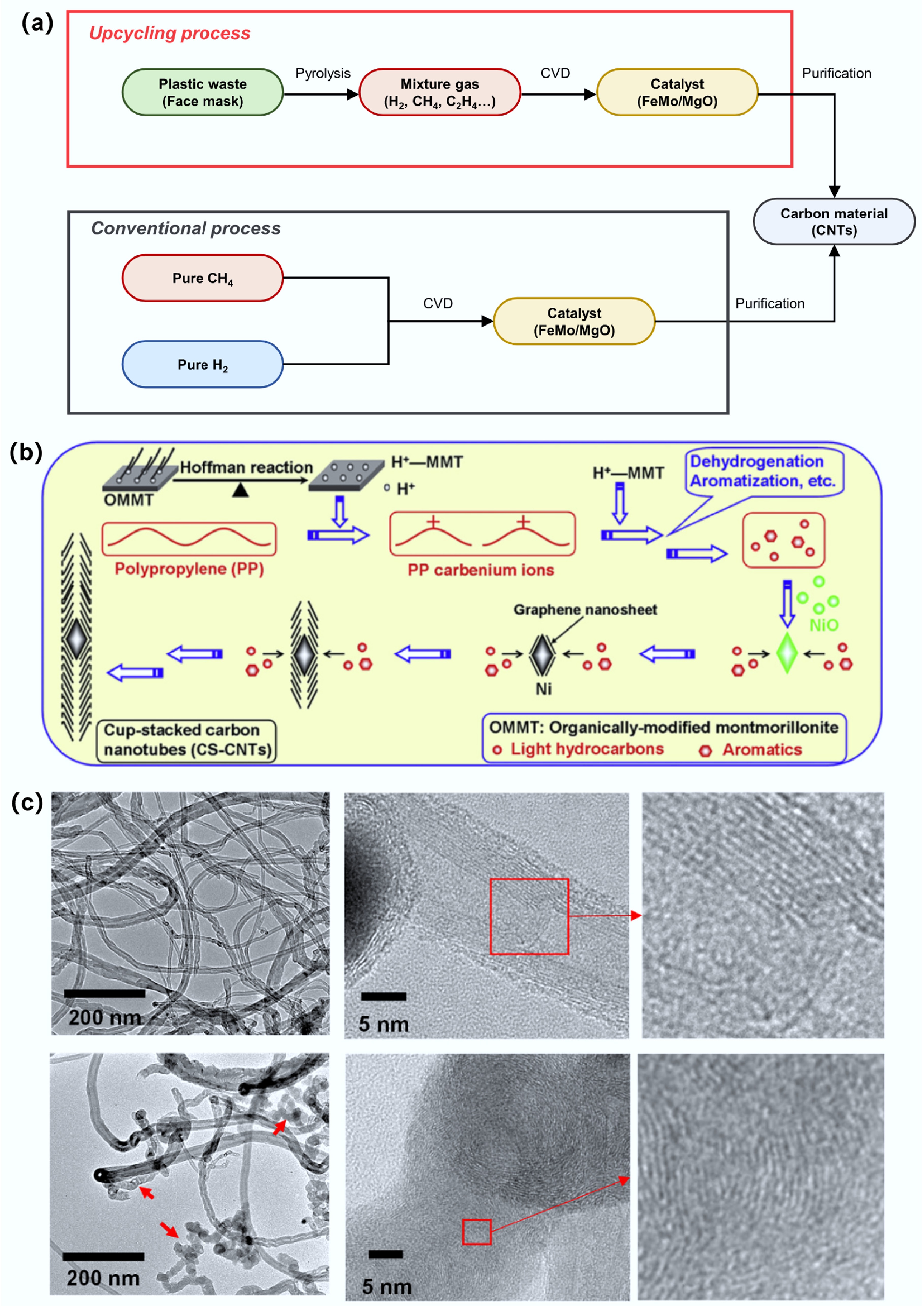
Figure 3.
(a) Comparison of progress between upcycling and conventional process for CNTs synthesis. Reproduced with permission[30] (Copyright 2024 Elsevier). (b) Schematic diagram of high-quality cup stacked carbon nanotubes (CS-CNTs) synthesized using polypropylene as raw material and organic modified montmorillonite (OMMT)/NiO as catalyst. Reproduced with permission[46] (Copyright 2013 Elsevier). (c) TEM images of MWCNTs from polyolefin alone and MWCNTs from polyolefin and sludge (9.1 wt%). Reproduced with permission[32] (Copyright 2024 Elsevier).
-
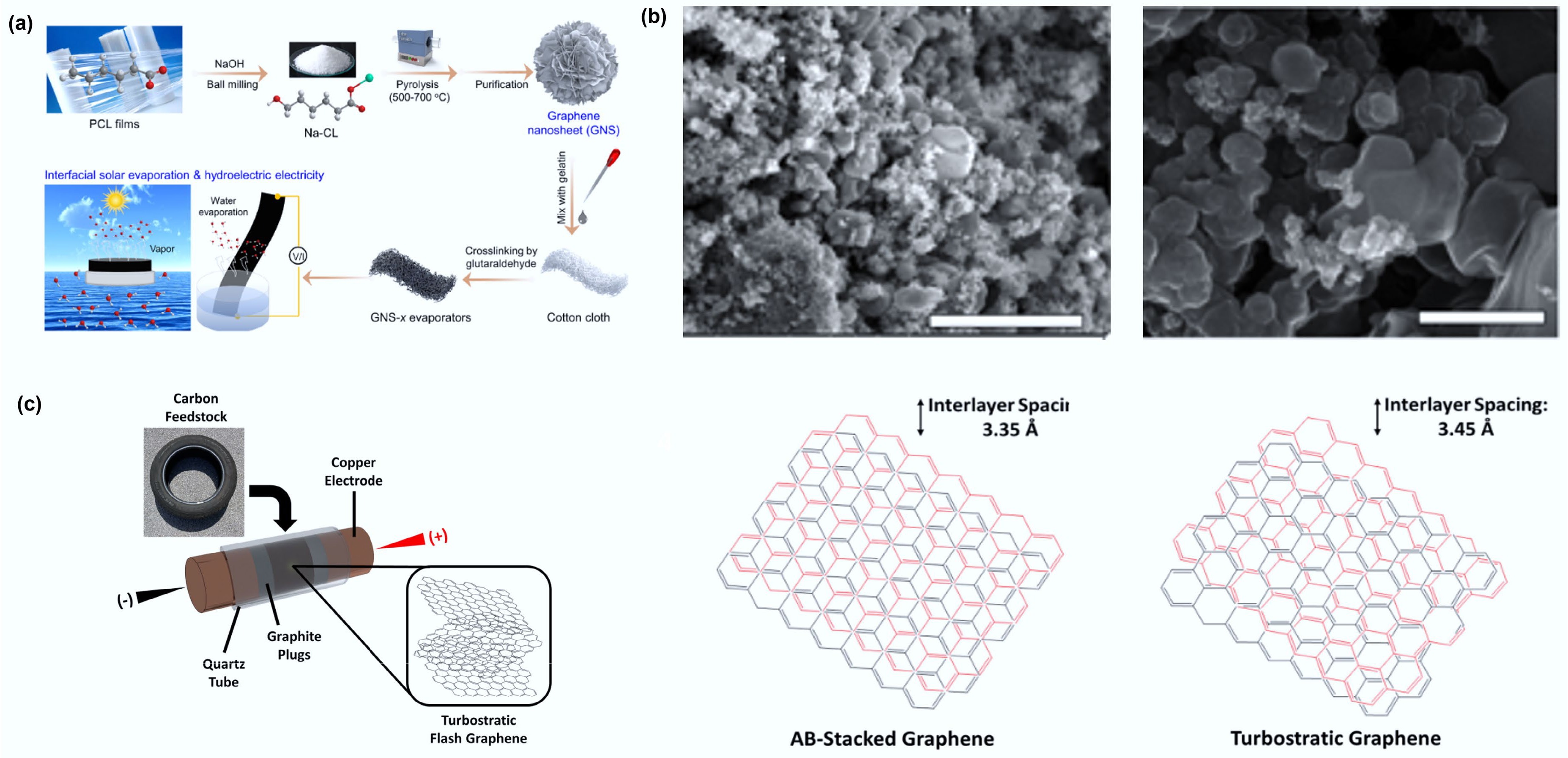
Figure 4.
(a) Design for the preparation of GNS-x evaporators from waste plastic for interfacial solar-driven evaporation and hydrovoltaic power generation. Reproduced with permission[50] (Copyright 2024 Elsevier). (b) SEM images of wrinkled graphene (left) and tFG crystals (right). The scale bars on the left and right are 3 μm and 500 nm, respectively. Reproduced with permission[51] (Copyright 2021 Elsevier). (c) Schematic depicting the sample setup of the FJH system for conversion of rubber waste into tFG. Reproduced with permission[52] (Copyright 2021 Elsevier).
-
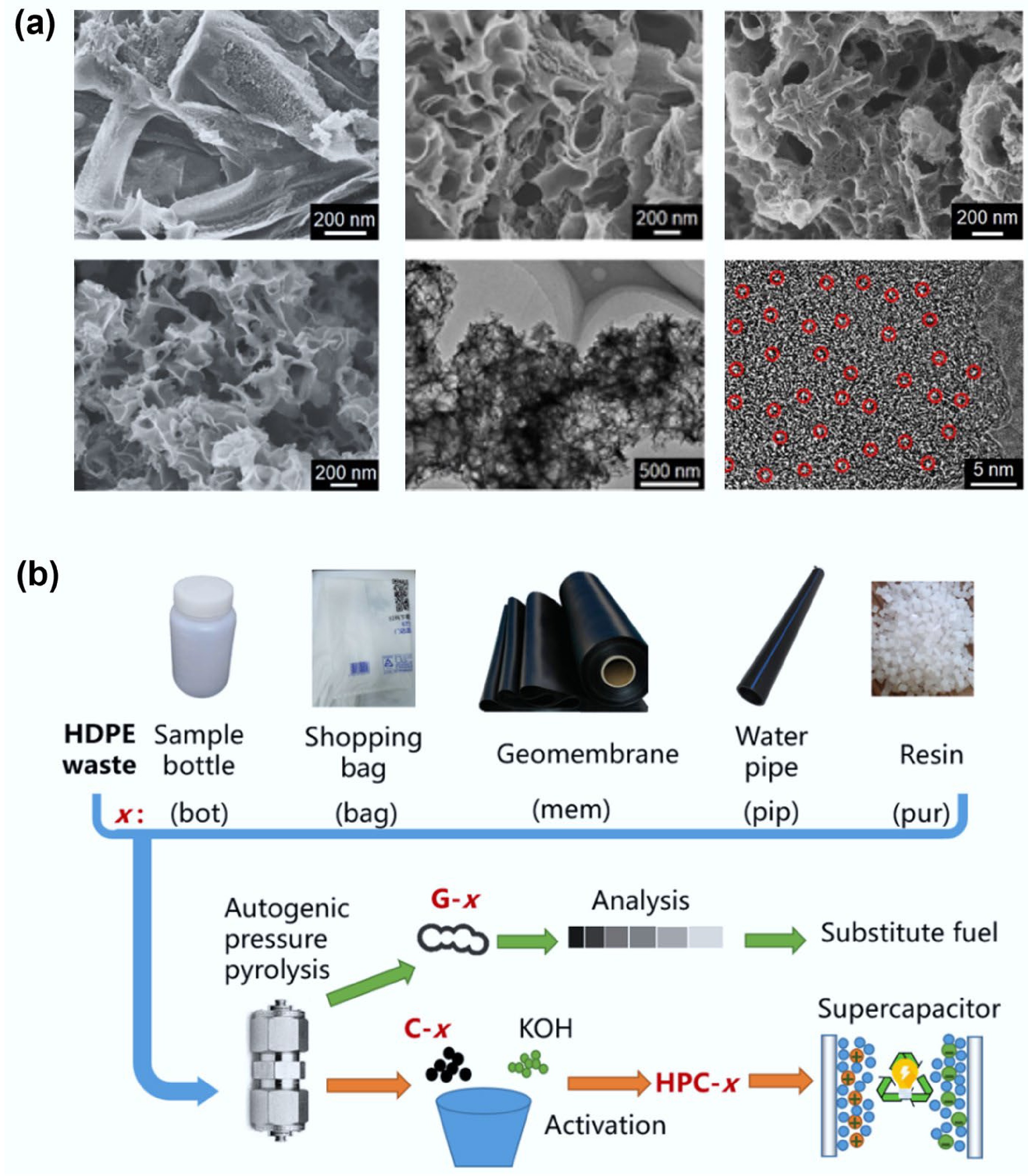
Figure 5.
(a) Researchers adjusted the ratio of ZnO/PET in the raw materials to prepare porous carbon materials with different pore structures. Reproduced with permission[58] (Copyright 2022 John Wiley and Sons). (b) Schematic diagram of preparing porous carbon from mixed plastics and using it for carbon dioxide capture. Reproduced with permission[36] (Copyright 2023 Elsevier).
-
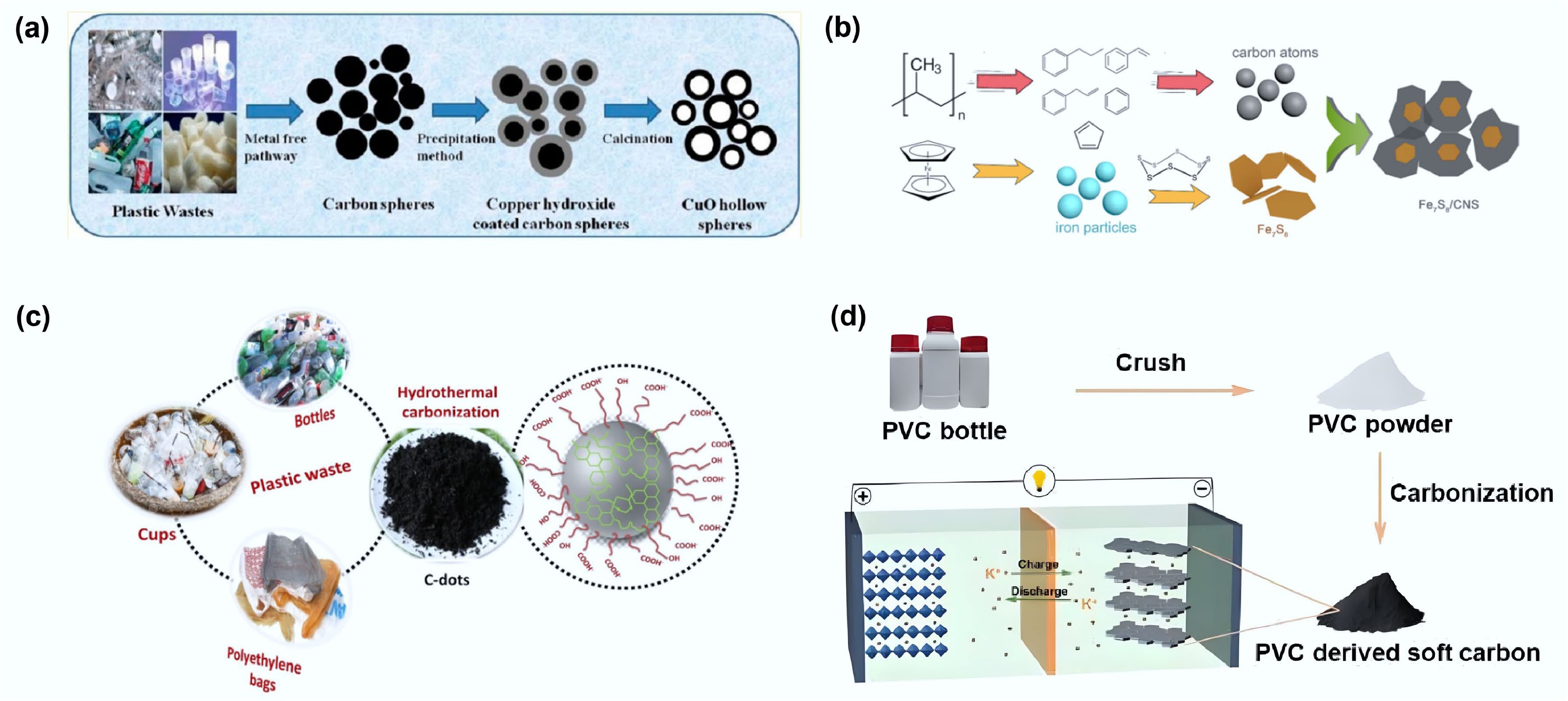
Figure 6.
(a) Schematic diagram of preparing carbon spheres from waste plastics and using them as templates to produce hollow copper oxide spheres. Reproduced with permission[37] (Copyright 2013 American Chemical Society). (b) Schematic drawing of the formation process of Fe7S8/CNS composite from waste PP. Reproduced with permission[38] (Copyright 2021 Elsevier). (c) Schematic illustration showing the formation of C-dots from different types of plastic waste. Reproduced with permission[40] (Copyright 2021 Elsevier). (d) PVC-derived soft carbon anodes for potassium-ion batteries. Reproduced with permission[61] (Copyright 2023 John Wiley and Sons).
-
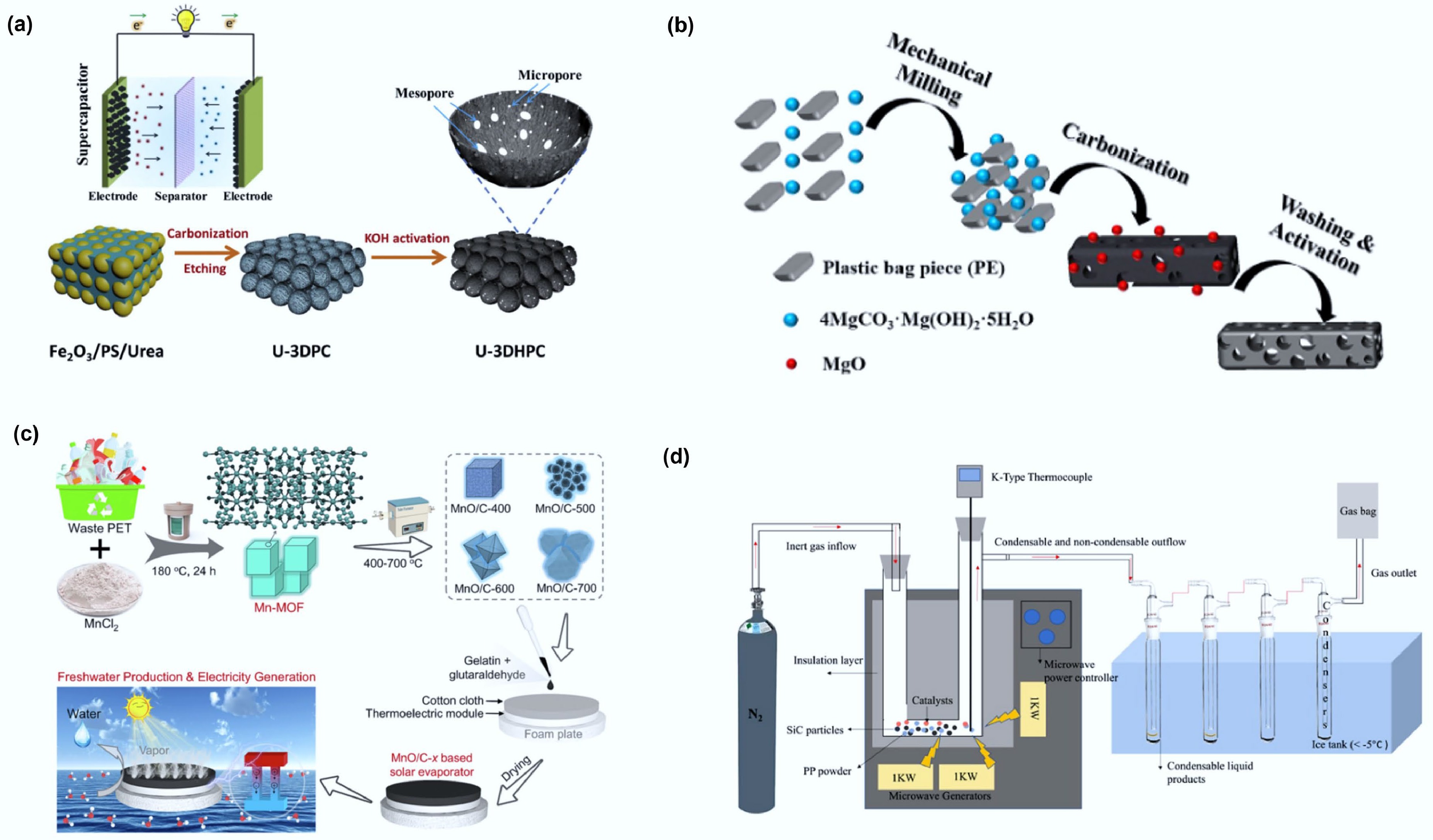
Figure 7.
(a) Schematic illustration of the synthetic process for the preparation of 3D hierarchically porous carbon. Reproduced with permission[71] (Copyright 2020 Elsevier). (b) Schematic illustration of the fabrication process for PE-HPC900NH3. Reproduced with permission[94] (Copyright 2019 Elsevier). (c) Scheme of preparing flexible MnO/C-x membrane for integrated interfacial solar evaporation and thermoelectric power generation. Reproduced with permission[95] (Copyright 2023 Elsevier). (d) Schematic diagrams of the microwave pyrolysis reactor. Reprinted with permission[73] (Copyright 2024 American Chemical Society).
-
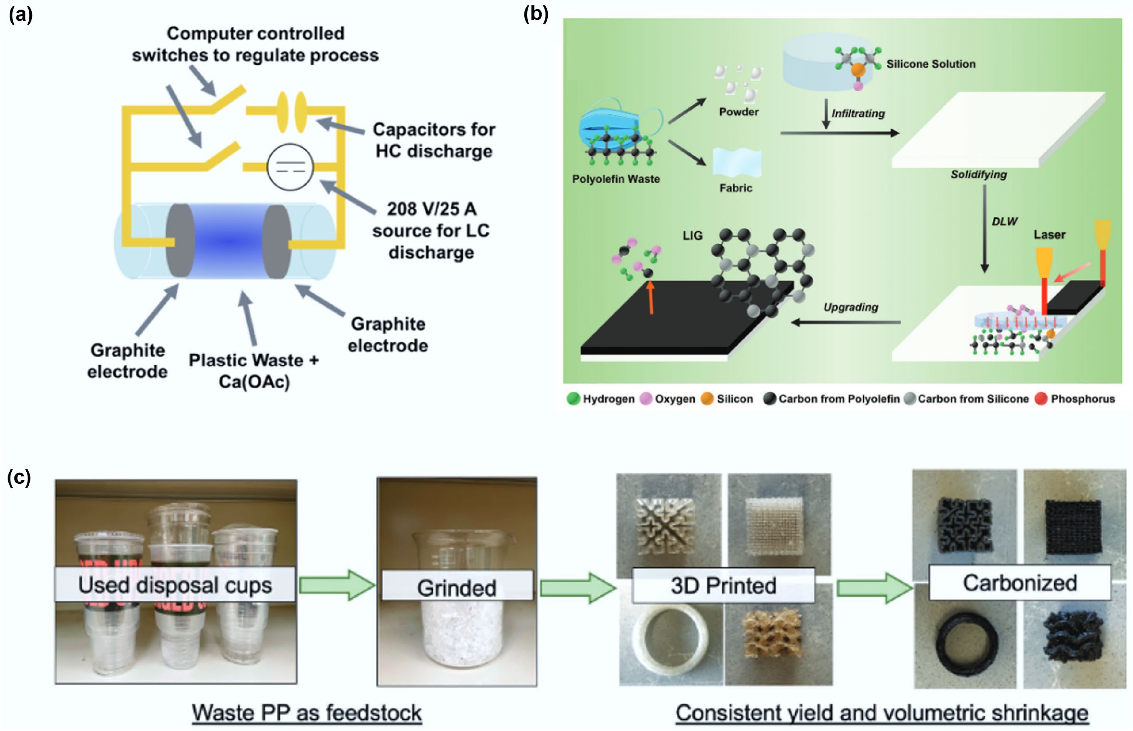
Figure 8.
(a) An FJH schematic composed of a 30 A, 208 V rectified power supply and a 128 mF capacitor allowing for LC and HC heating to be used in tandem. Reprinted with permission[76] (Copyright 2022 American Chemical Society). (b) Schematic illustrations of the processes and applications of upgrading polyolefin plastic waste into LIG using SA-DLW. Reproduced with permission[103] (Copyright 2024 John Wiley and Sons). (c) Upcycling scheme of PP waste to carbons, demonstrating feedstock, printed parts and final structured carbon materials. Reproduced with permission[104] (Copyright 2023 John Wiley and Sons).
-
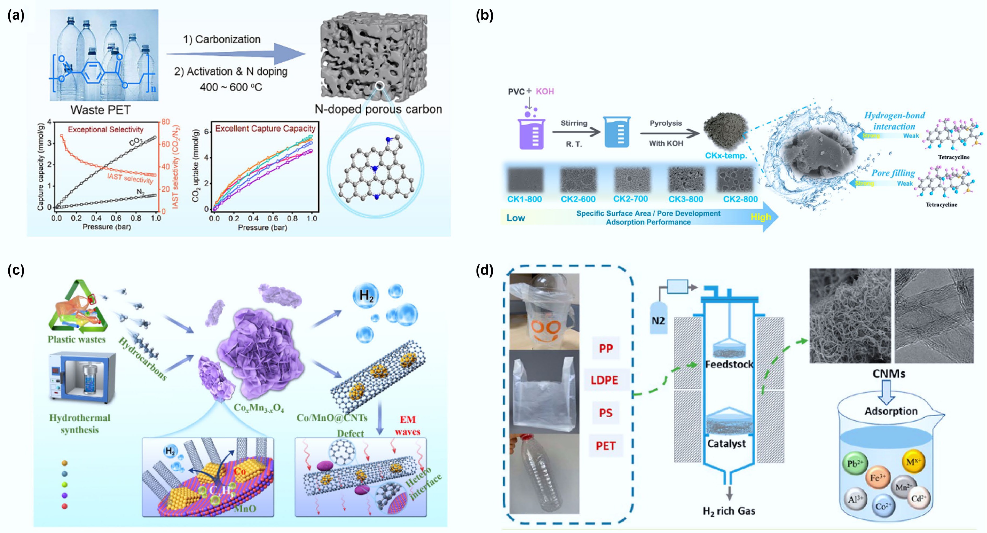
Figure 9.
(a) Synthesis of nitrogen doped hierarchical porous carbon from polyethylene terephthalate and its adsorption performance for carbon dioxide. Reproduced with permission[109] (Copyright 2024 Elsevier). (b) Schematic diagram of the adsorption process of tetracycline using carbonization activation method to prepare PVC into porous carbon material. Reproduced with permission[110] (Copyright 2023 Elsevier). (c) Schematic fabrication procedure of the Co/MnO@CNTs nanocomposites and the working mechanism on electromagnetic waves. Reproduced with permission[111] (Copyright 2023 Elsevier). (d) Schematic diagram of carbon nanomaterials produced by pyrolysis and catalytic reforming of waste plastics for metal ion adsorption. Reprinted with permission[67] (Copyright 2022 American Chemical Society).
-
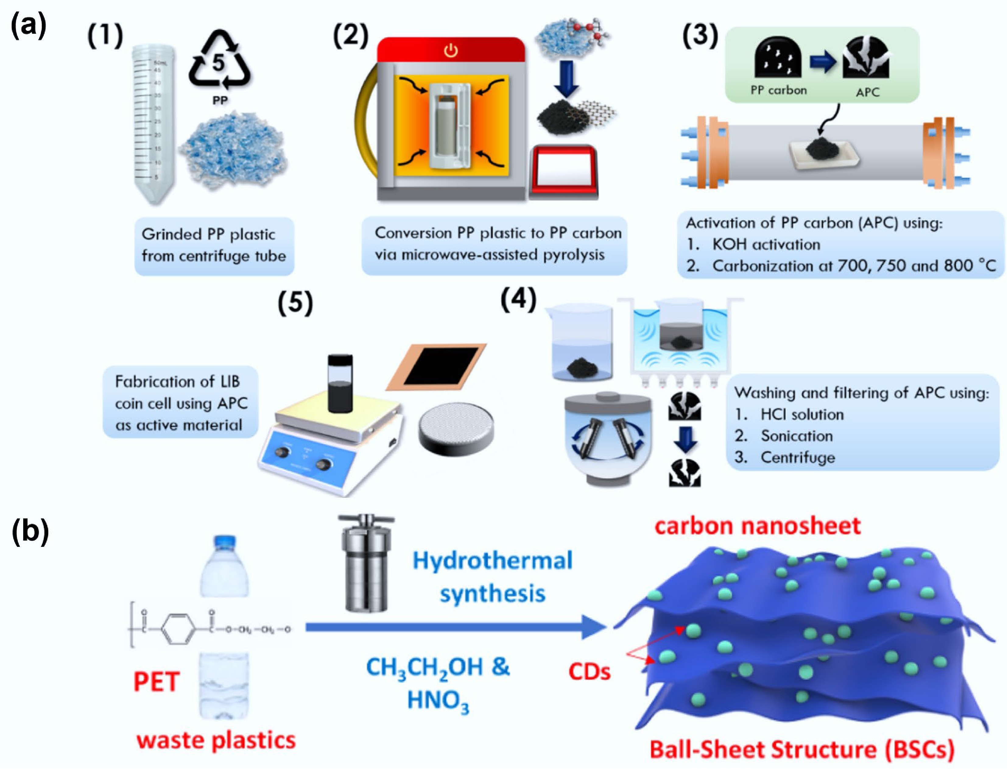
Figure 10.
(a) The proposed schematic shows APC electrode synthesis for lithium-ion batteries. Reproduced with permission[123] (Copyright 2024 Elsevier). (b) Schematic of the synthesis of plastic-derived, ball-sheet structure carbon (PBSC) from PET involving nitric acid and ethanol. Reproduced with permission[124] (Copyright 2024 Elsevier).
-
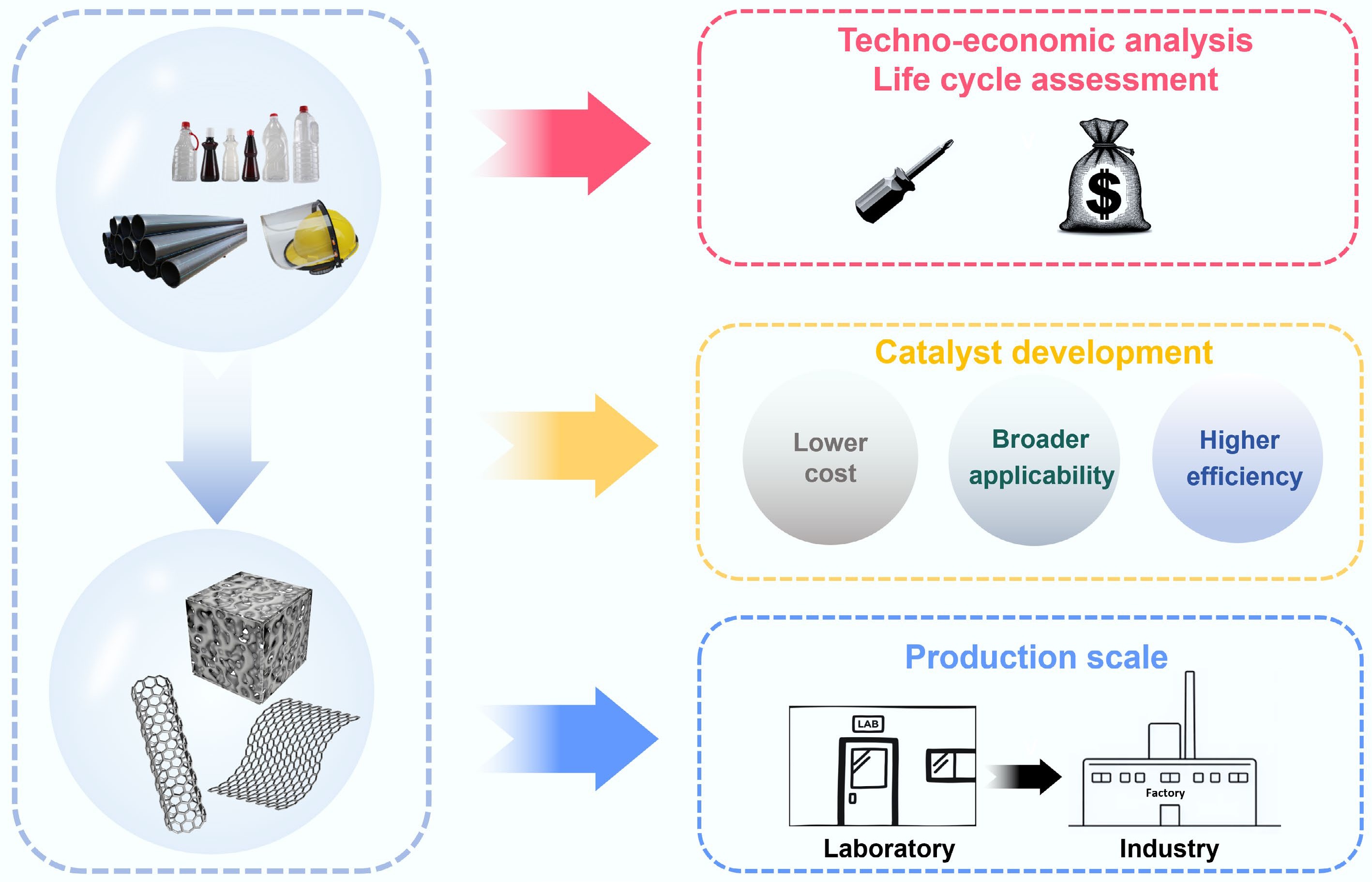
Figure 11.
Key challenges for synthesizing functional carbon materials from waste plastics.
-
Carbon functional materials Types of plastics Method Specific surface area (m2/g) Characteristic
parameterID/IG Carbon
yield (%)Application Ref. Carbon
nanotubesMixed plastic Catalytic pyrolysis − − 0.30−0.34 − − [30] PP Catalytic pyrolysis 1.37–46.51 10–30 nm
(outside diameter)0.45−0.81 93 − [31] HDPE/LDPE/PS Catalytic pyrolysis − 16–19 nm (outside diameter) 0.9−1.5 37 ± 7 − [32] Graphene PET Chemical vapor deposition − − 0.38 (IG/I2D) − − [33] Porous
carbonMixed plastic Direct pyrolysis 596.01–2,328.2 − 0.806−0.942 − Lithium selenium batteries and zinc ion hybrid supercapacitors [34] PS Catalytic pyrolysis 1,033.58 − 0.95−1.12 − Palm oil hydroprocessing [35] HDPE Self-pressurized pyrolysis 2,785–2,913 − 0.79−0.94 67.49 Supercapacitor [36] Carbon
spheresPP One-pot synthesis − 1–8 μm (diameter) 0.57 42.4 Synthesis of nanocrystalline copper oxide [37] HDPE − 0.6 35.6 PVC − 0.55 33.6 Carbon nanosheets PP One-pot synthesis 3,200 4–4.5 nm (thickness) 0.53–0.80 62.8 Supercapacitor [38] PE Direct pyrolysis 1,043.4 − 0.92 4.2 Organic pollutant degradation [39] PP 765.1 0.89 0.9 PVC 703.7 1.03 28.6 Carbon
quantum
dotsPE One-pot synthesis − 5–30 nm (size) − 64 Determination of biocompatibility activity [40] PE/PP One-pot synthesis − − − − Determination of the concentrations of three iron ions in aqueous solution [41] Soft carbon PE One-pot synthesis − − − − Lithium ion battery [42] Table 1.
Comparative characteristics of waste plastics as precursors for different functional carbon materials
-
Method Types of plastics Reaction conditions Reaction
timeSpecific surface area (m2/g) Main carbon products Carbon recovery (%) Application Ref. Direct pyrolysis PET 5 °C/min to 600 °C 1 h 637 Porous carbon 21.7 CF4 adsorption [64] PE 5 °C/min to 700 °C 3 h 157 Porous carbon 80 Sodium-ion batteries [65] Catalytic pyrolysis HDPE 500 °C
(pyrolysis section)
800 °C
(catalytic section)− − Carbon nanotubes 27 − [66] LDPE − − Carbon nanotubes 28 − PP − − Amorphous carbon 39.5 − PS − − Amorphous carbon 2 − PET − − Amorphous carbon 1.92 − LDPE 15 °C/min to 500 °C 50 min − Carbon nanotubes 32 − [67] PP 15 °C/min to 500 °C 50 min − Carbon nanotubes 30 − PS 15 °C/min to 500 °C 50 min − Carbon nanotubes 38.26 − PET 15 °C/min to 500 °C 50 min − Amorphous carbon 3.01 − PVC 15 °C/min to 500 °C − − Carbon nanotubes 36.5 − [68] One-pot synthesis PET 600 °C 1 h 1,263 Porous carbon − Carbon dioxide adsorption [69] PVC 5 °C/min to 700 °C 30 min 1,922 Carbon nanotubes/
porous carbon89.68 − [70] Template method PS 700 °C 1 h 2,100 Porous carbon − Supercapacitor [71] PET 850 °C 2 h 421 Porous carbon − Reductive alkylation reaction [72] Microwave-assisted pyrolysis PP 800 °C − − Carbon nanotubes − − [73] Mix plastic 1,000 W 3−5 min − Carbon nanotubes − − [74] Flash joule heating HDPE − 1−3 s − Carbon nanotubes − − [75] HDPE 208 V (current increases
from 0.1 to 25 A)50 s 874 Graphene − Hydrogen evolution reaction catalyst [76] Table 2.
Comparison of different methods for preparing functional carbon materials using waste plastics
Figures
(11)
Tables
(2)