-
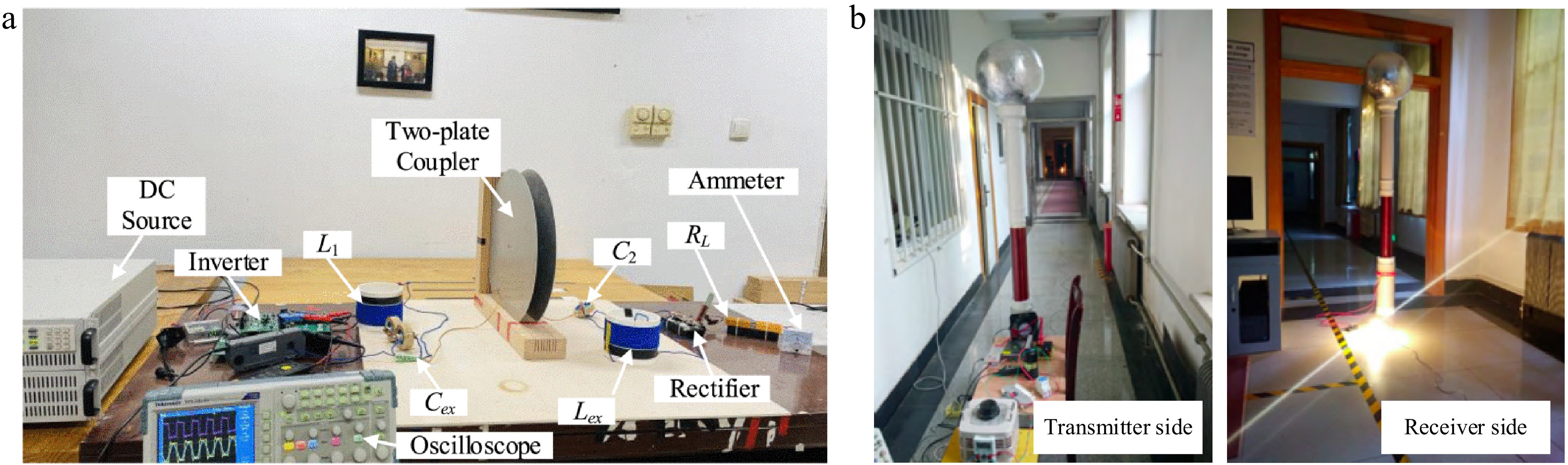
Figure 1.
Experimental prototype of electric field power transfer technology based on earth coupling. (a) SCC-WPT. (b) SWPT.
-
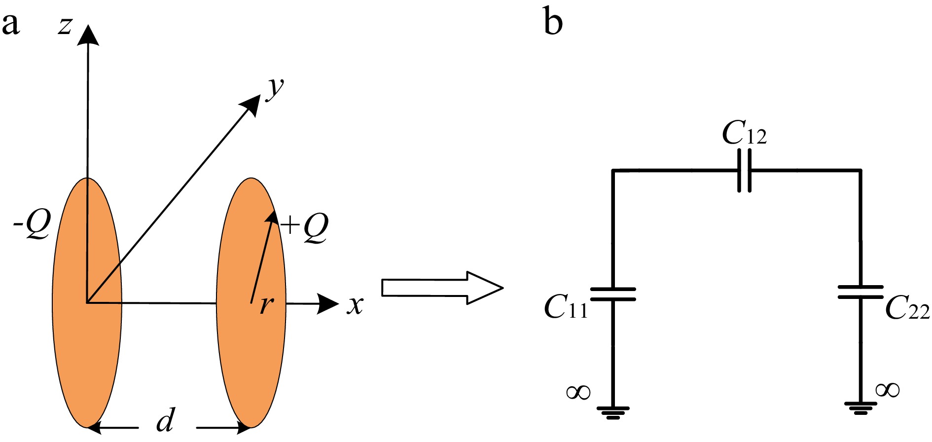
Figure 2.
Parallel disk capacitance model with opposite polarity. (a) 3D diagram. (b) Circuit diagram.
-
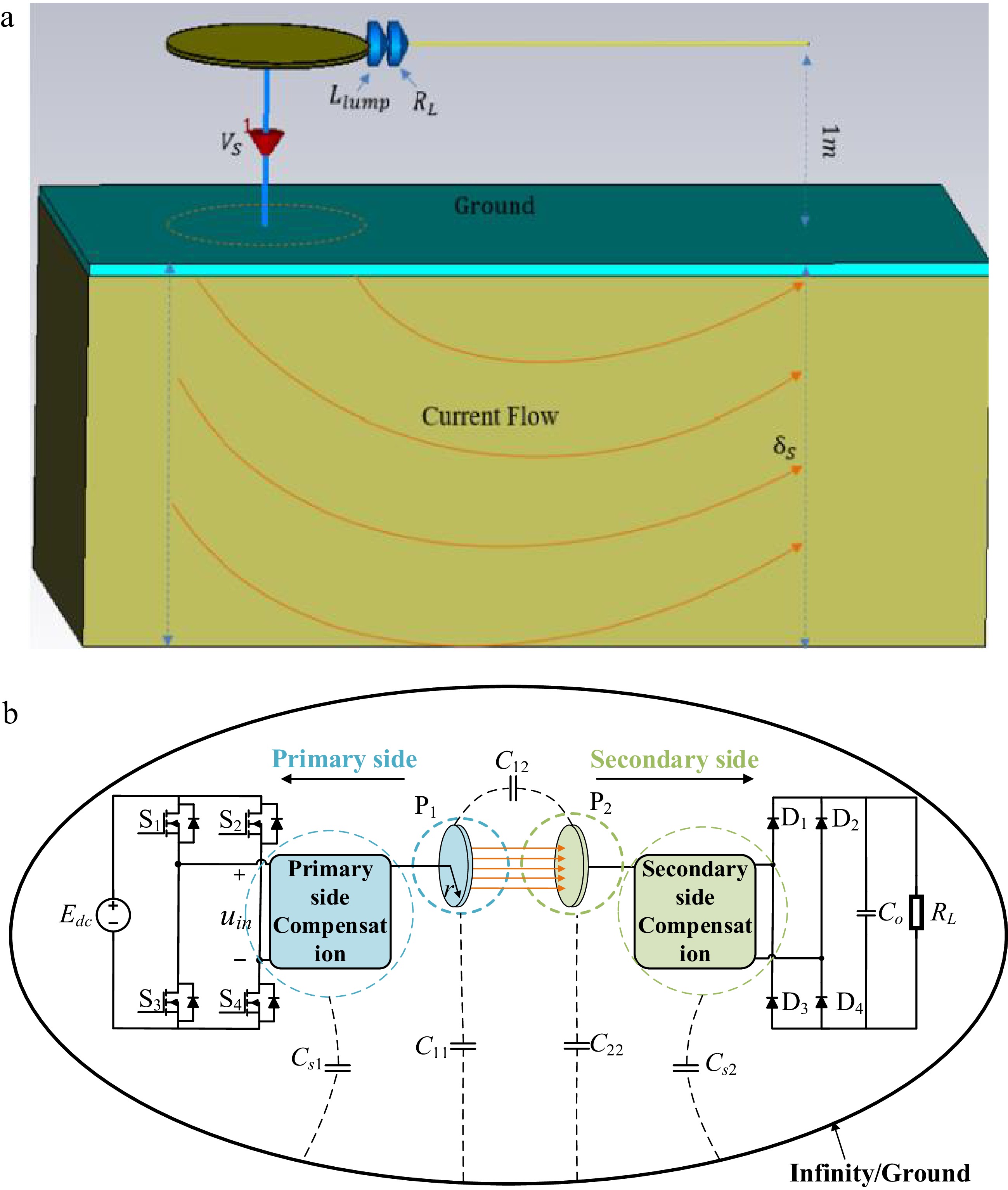
Figure 3.
SCC-WPT system structure diagram. (a) Theory of strong ground coupling. (b) Stray capacitance and self-capacitance theory.
-
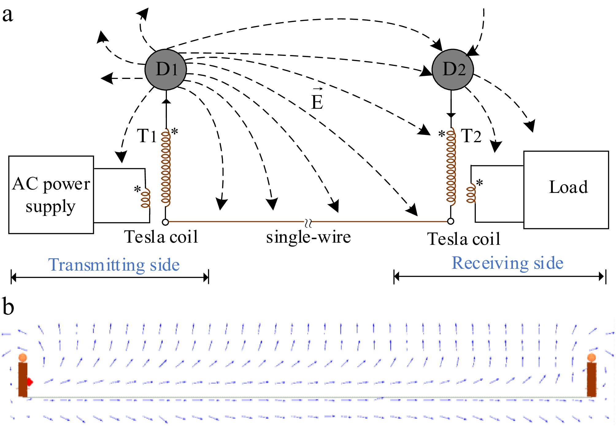
Figure 4.
Field distribution of SWPT at different transfer distances. (a) Schematic diagram of the short-distance SWPT system. (b) Poynting vector distribution of the long-distance SWPT system.
-
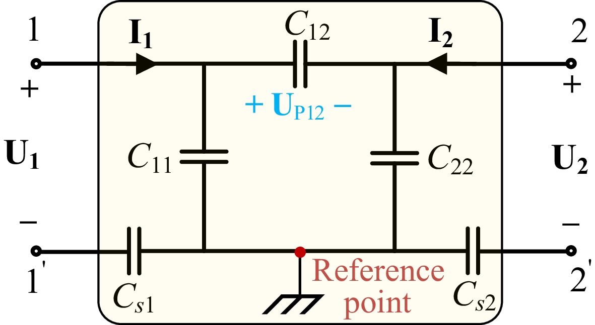
Figure 5.
Two-port network of the circuit model.
-
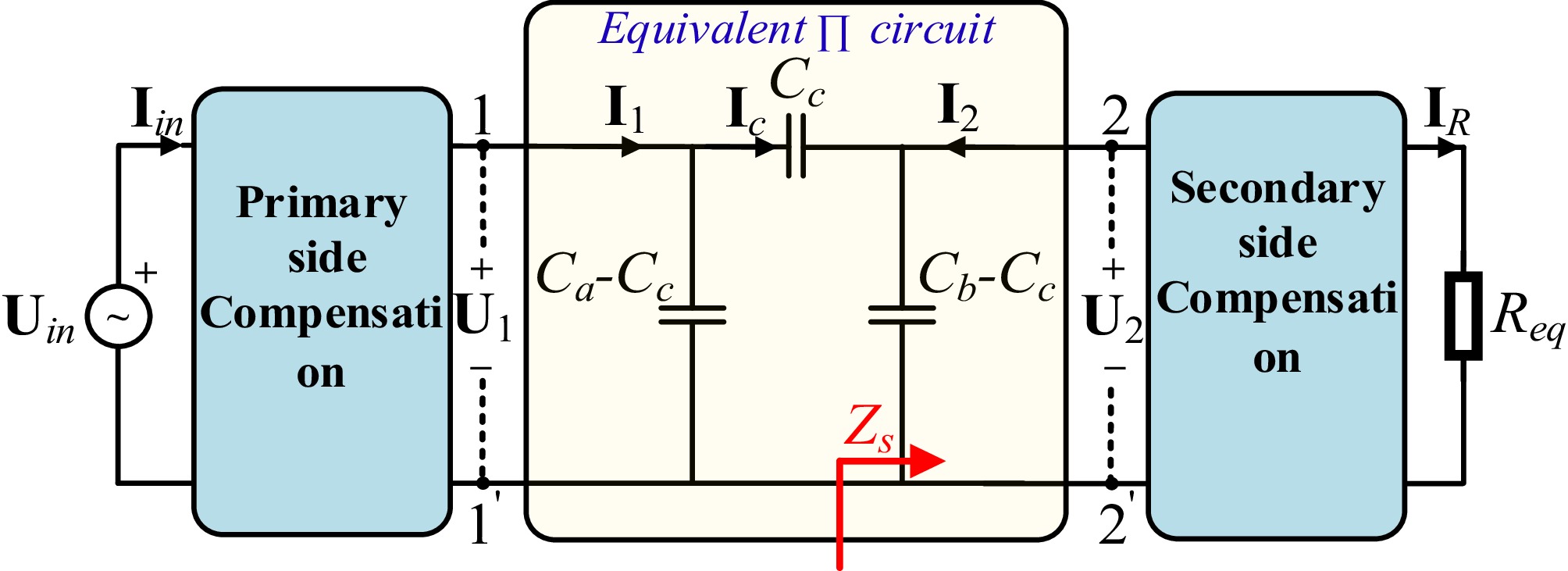
Figure 6.
Equivalent circuit of the SCC-WPT system.
-

Figure 7.
Equivalent circuit model of SWPT system. (a) SWPT system model using a multi-layer Tesla coil structure. (b) SWPT system model using a limiter.
-
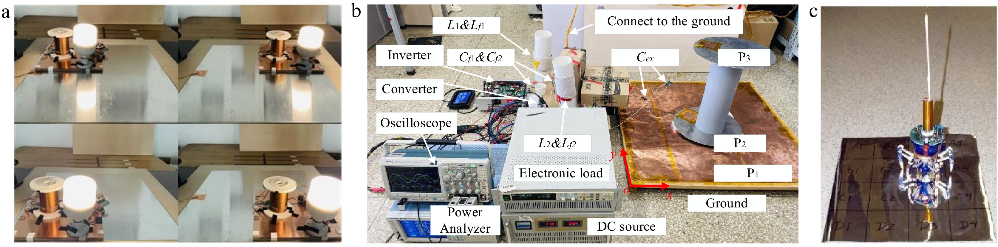
Figure 8.
Application of SCC-WPT in wireless charging plane. (a) Flexible power supply system. (b) Large-area free-position power supply system. (c) Robot free-position power supply system.
-
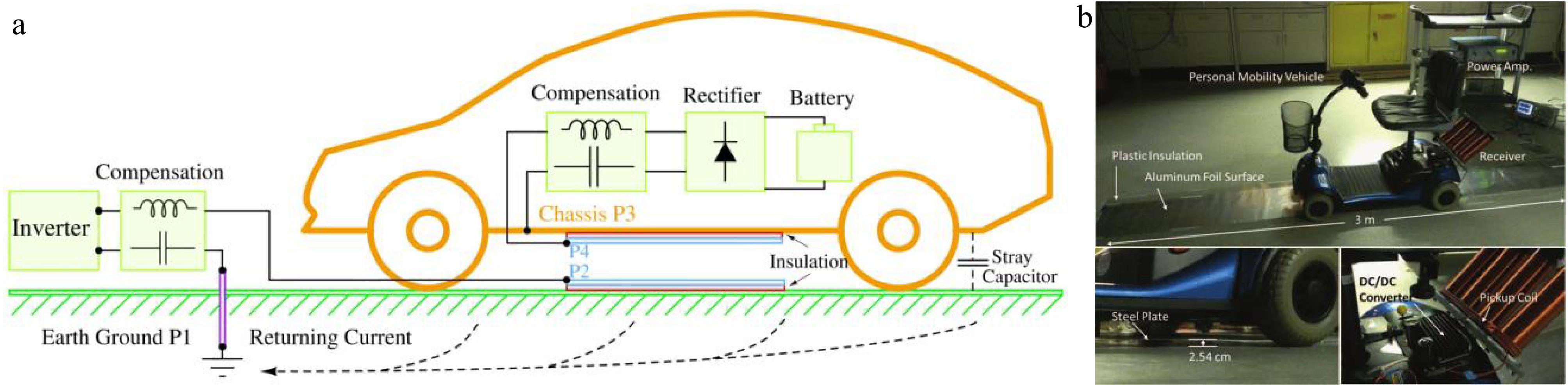
Figure 9.
Application of SCC-WPT technology in transportation. (a) Static wireless charging EV. (b) Dynamic wireless charging mobile EV.
-

Figure 10.
Application of SWPT technology in underwater equipment. (a) A 51 m underwater SWPT system. (b) A 10 m underwater SWPT system.
-
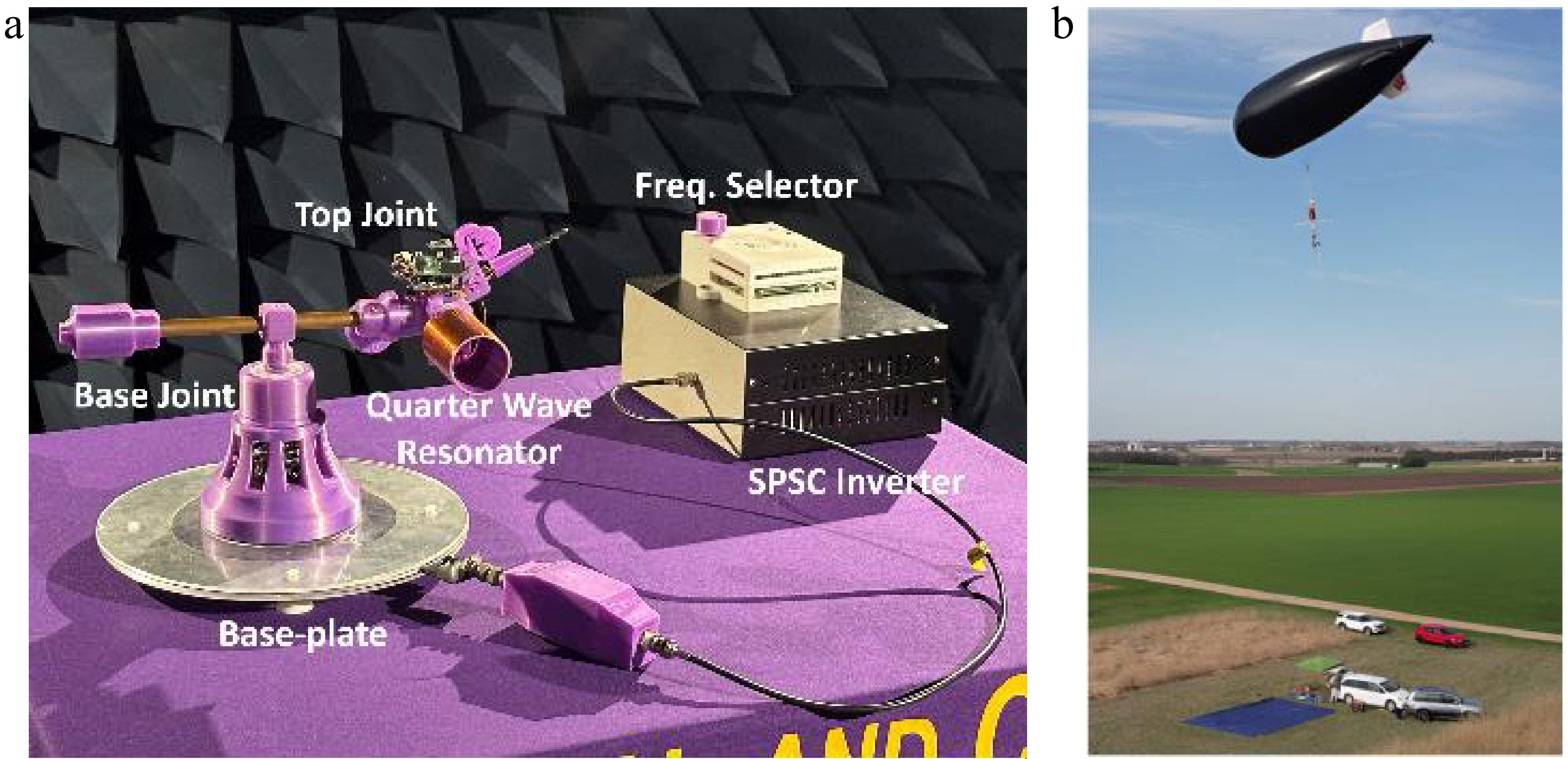
Figure 11.
Application of SCC-WPT and SWPT technology in industrial applications. (a) For the robotic arm. (b) For an aerial platform.
-
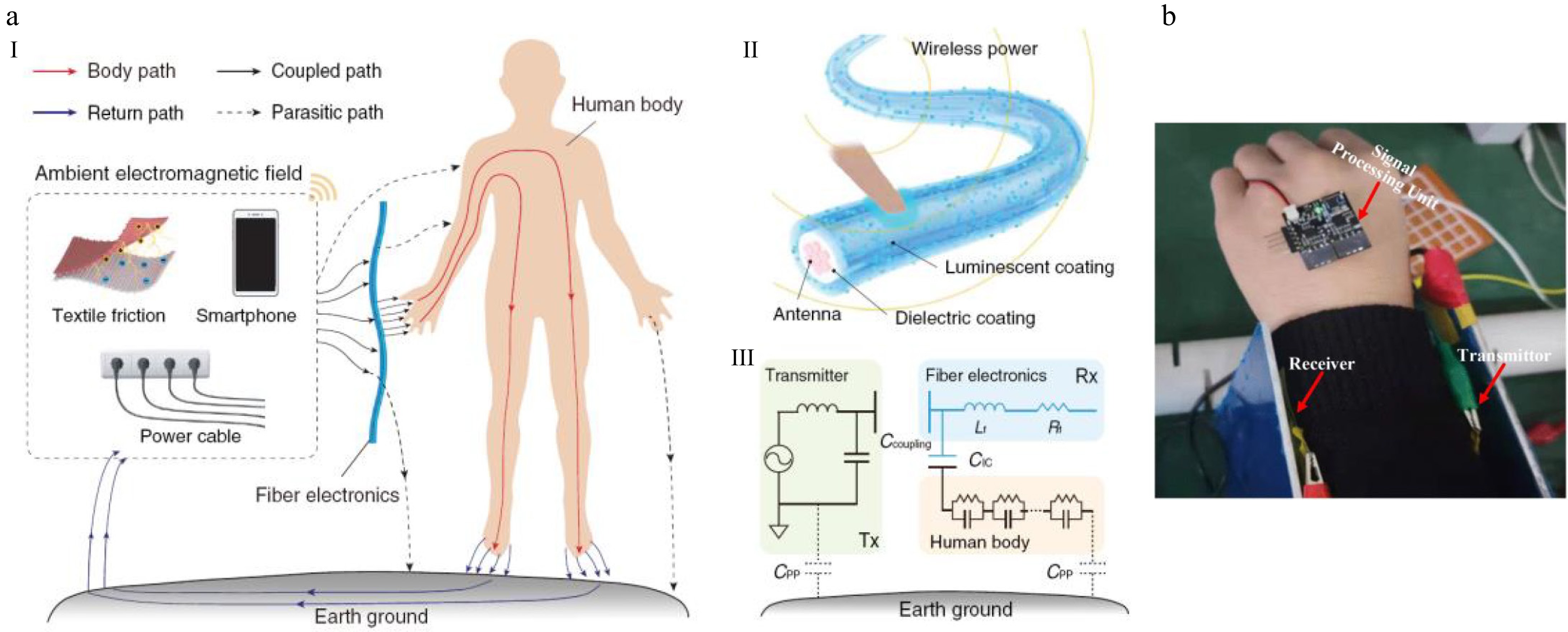
Figure 12.
Application of SCC-WPT technology in wearable devices. (a) Schematic diagram of I-fiber harvesting energy in various situations. (b) Wireless power transfer is realized when metal plates interfere and thin films bend.
-
Classification Frequency Distance Power Efficiency Ref. SCC-WPT 3.3 MHz 3 mm 3.6 W 35% [9] 1 MHz 50 mm 266 W 62% [10] 1.97 MHz 5 mm 106.9 W 56.2% [12] 741.5 kHz 550 mm 20 W 19.5% [15] 2.74 MHz 25.4 mm 36 W 20% [31] 2 MHz 17 mm 700 W 91% [35] 1 MHz 110 mm 350 W 74.1% [36] 2 MHz 10 mm 30 W 30% [37] 85 kHz 50 mm (seawater) 1.2 kW 91% [47] 200 kHz 100 cm (seawater) 300 W 91.07% [48] SWPT 847 kHz 2 m 200 W 61% [17] 10.55 MHz 5 m 65.28 W 72.08% [23] 6.7 kHz 5 km 5 kW 87% [20] 220 kHz 30 m 500 W 92% [40] 580 kHz 4.5 m (salt water) 25 W 54% [13] 40 kHz 51 m (salt water) 30.2 W 51.8% [49] 300 kHz 10 m (seawater) 206.8 W 83% [50] * Unless otherwise specified in the table, air is used as the transfer medium. Table 1.
Energy efficiency features of SCC-WPT and SWPT.
Figures
(12)
Tables
(1)