-
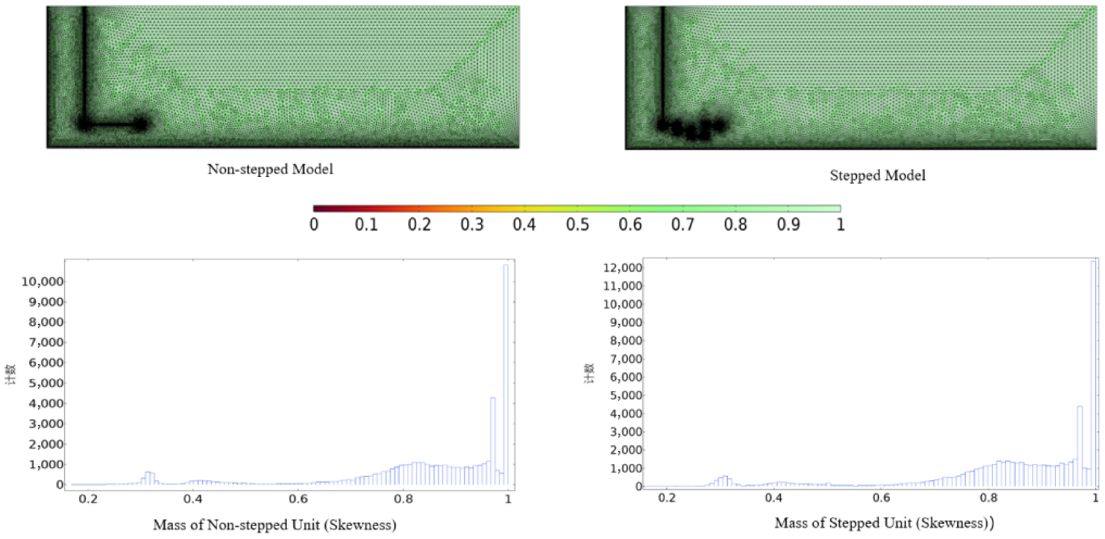
Figure 1.
Mesh generation and element quality.
-
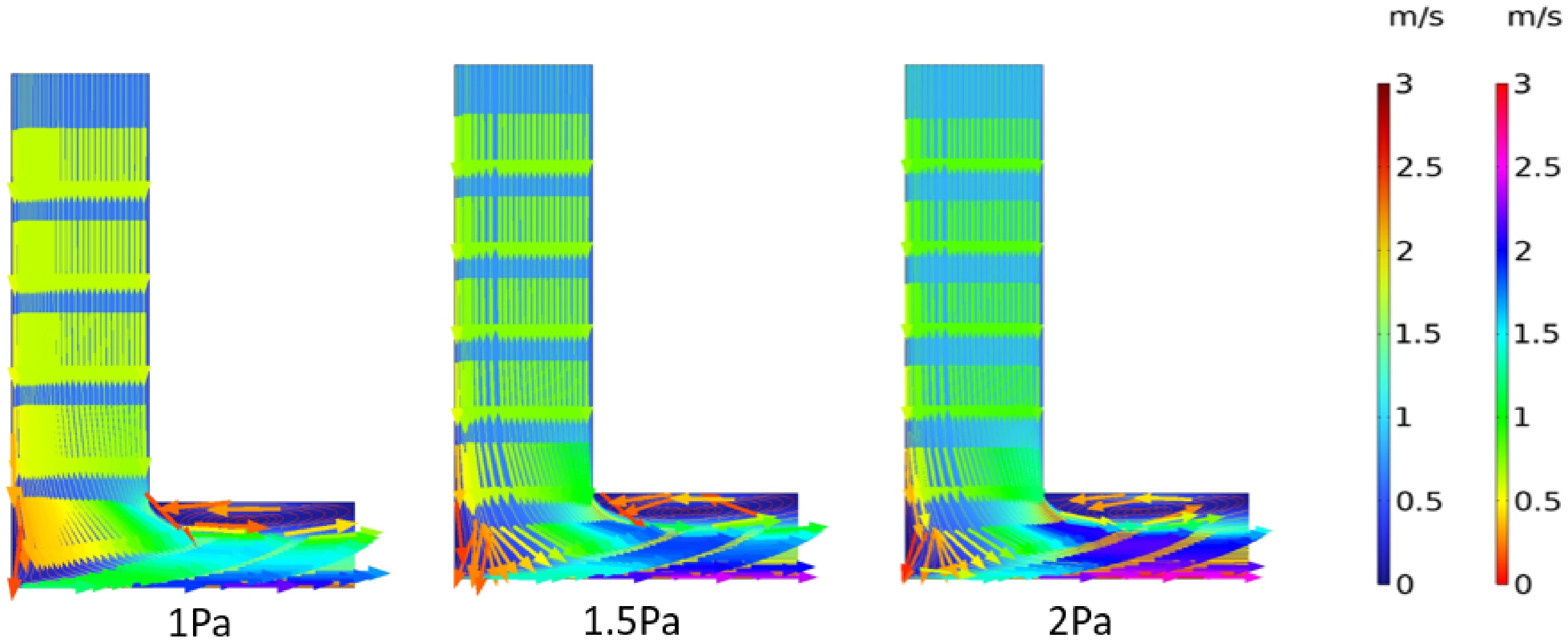
Figure 2.
Streamline diagram of the non-step structure.
-
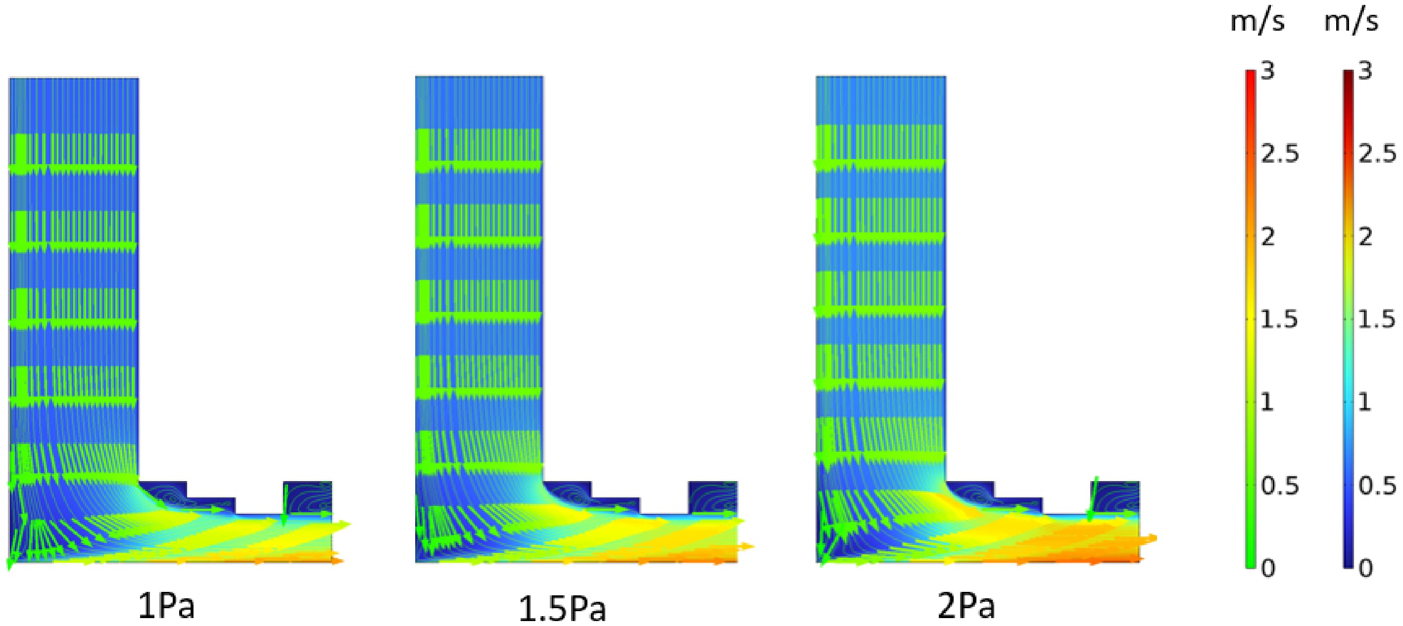
Figure 3.
Streamline diagram of the step structure.
-
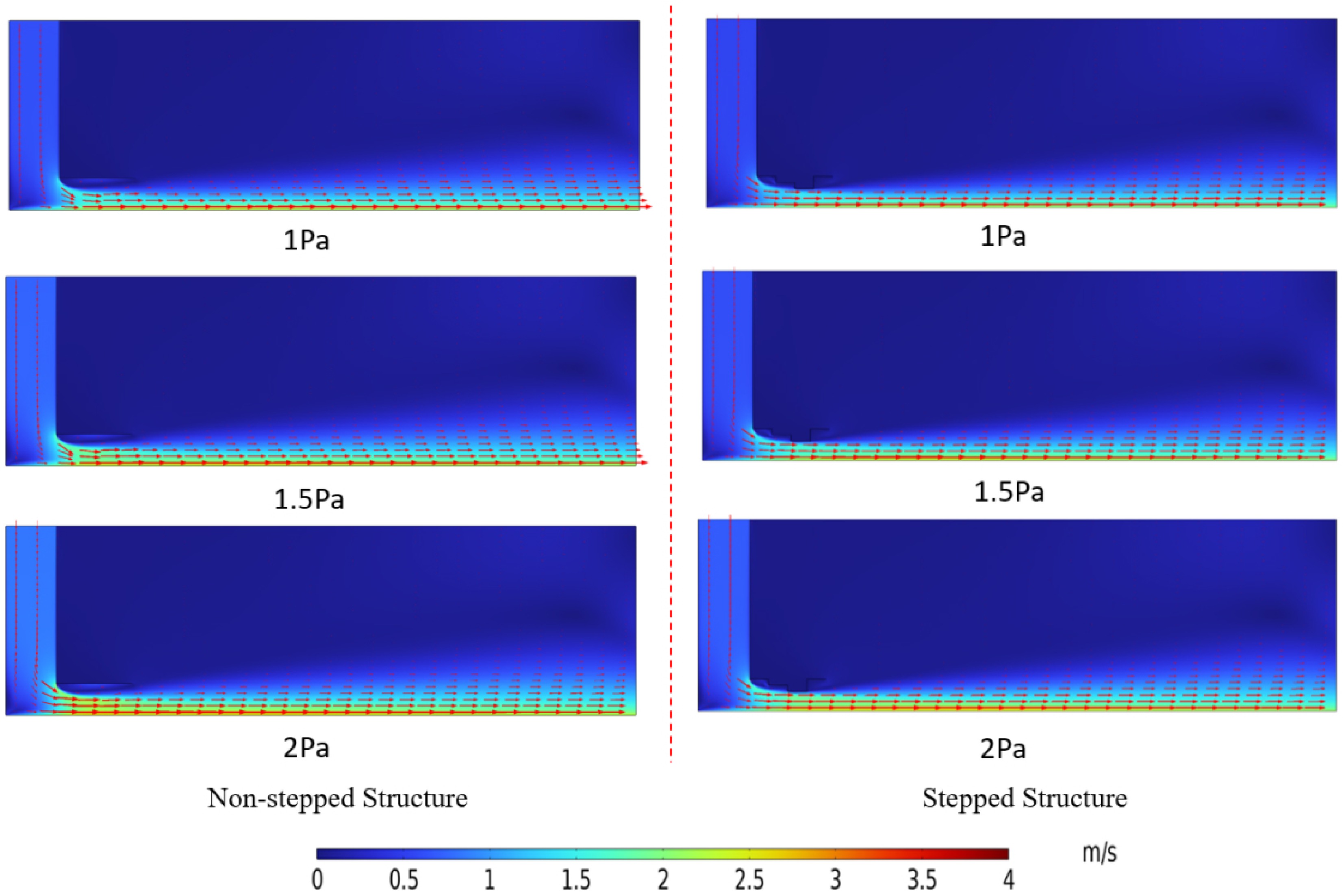
Figure 4.
Velocity field distribution diagram.
-
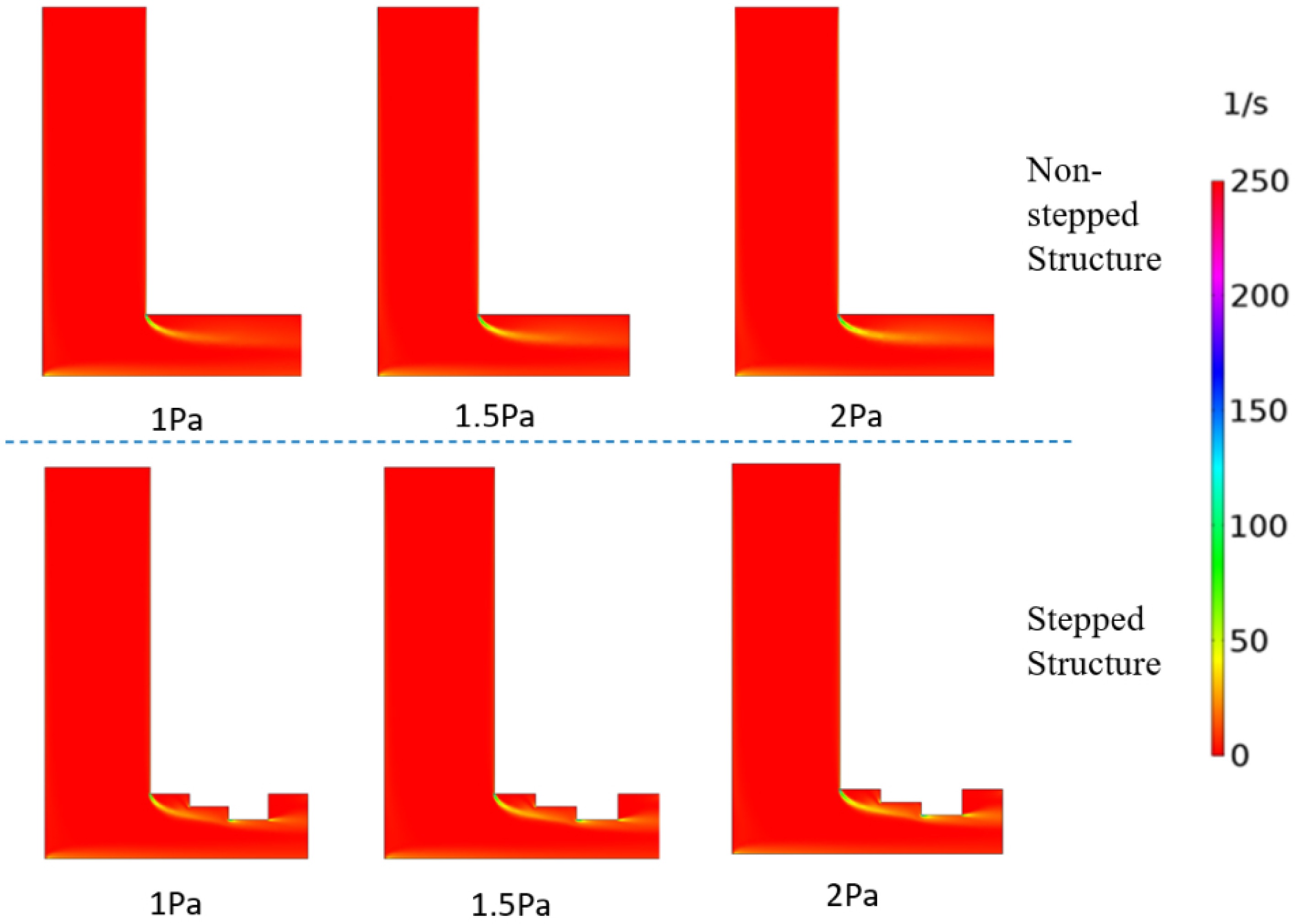
Figure 5.
Vorticity diagram.
-
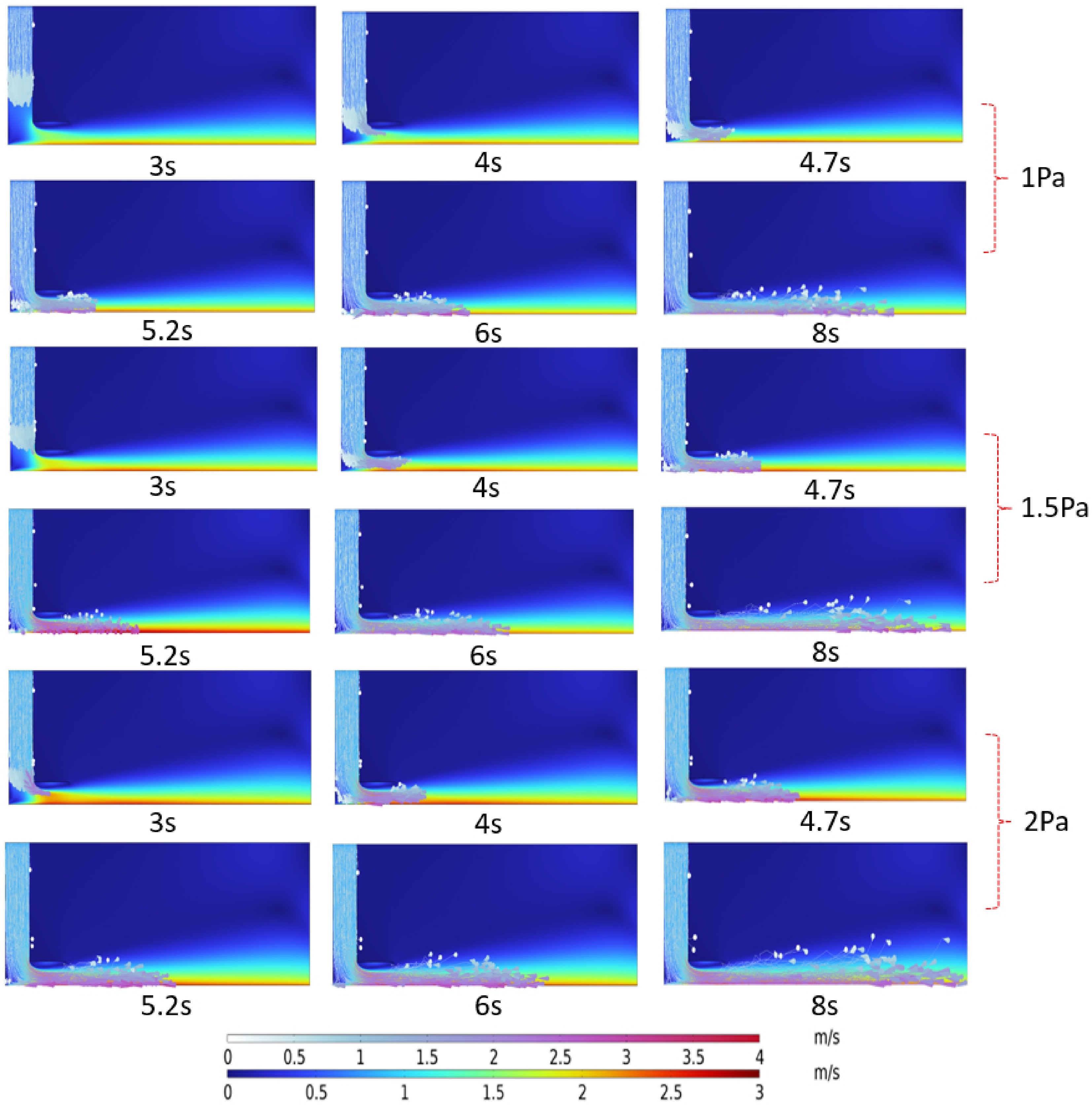
Figure 6.
Dust movement diagram of the non-step structure.
-
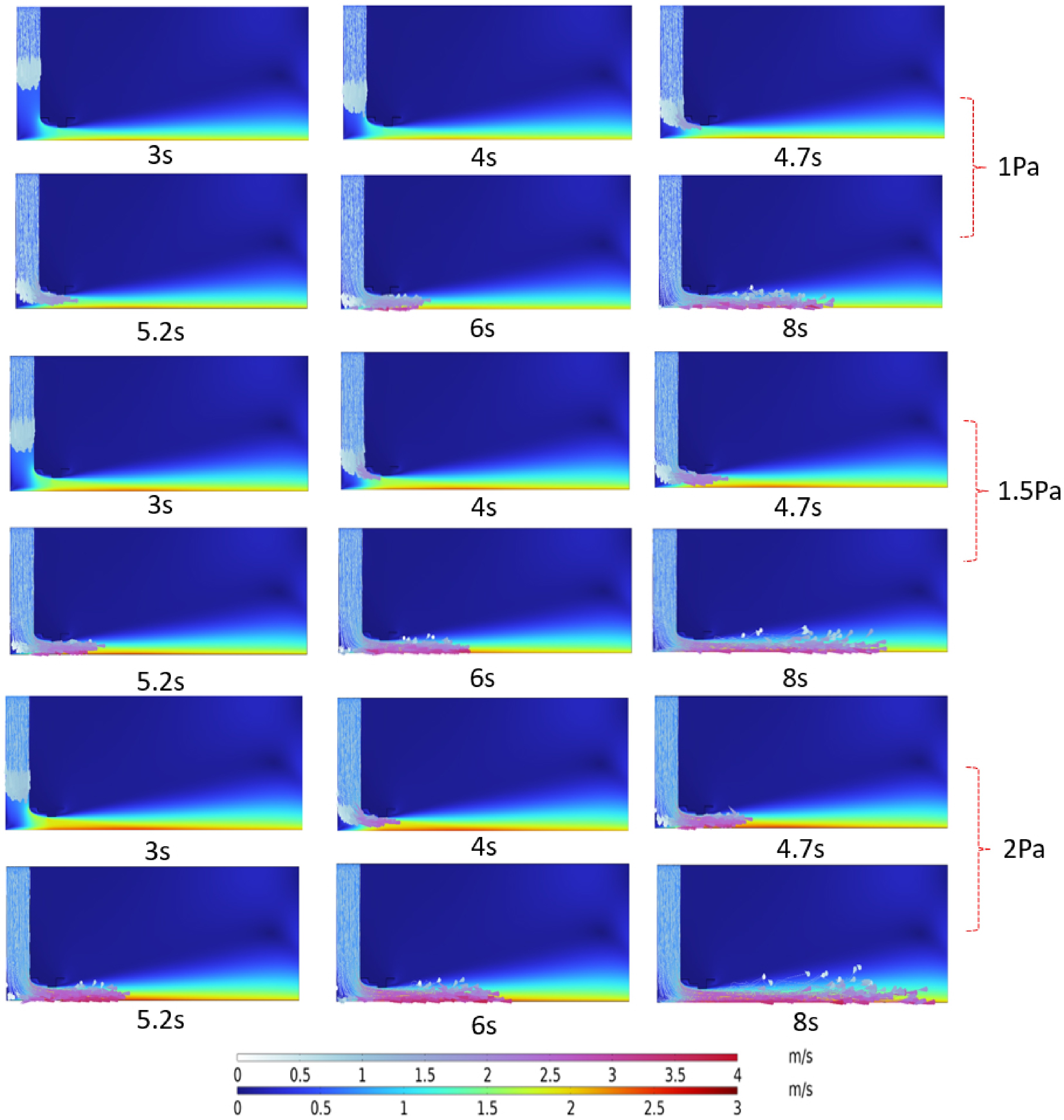
Figure 7.
Dust movement diagram of the step structure.
-
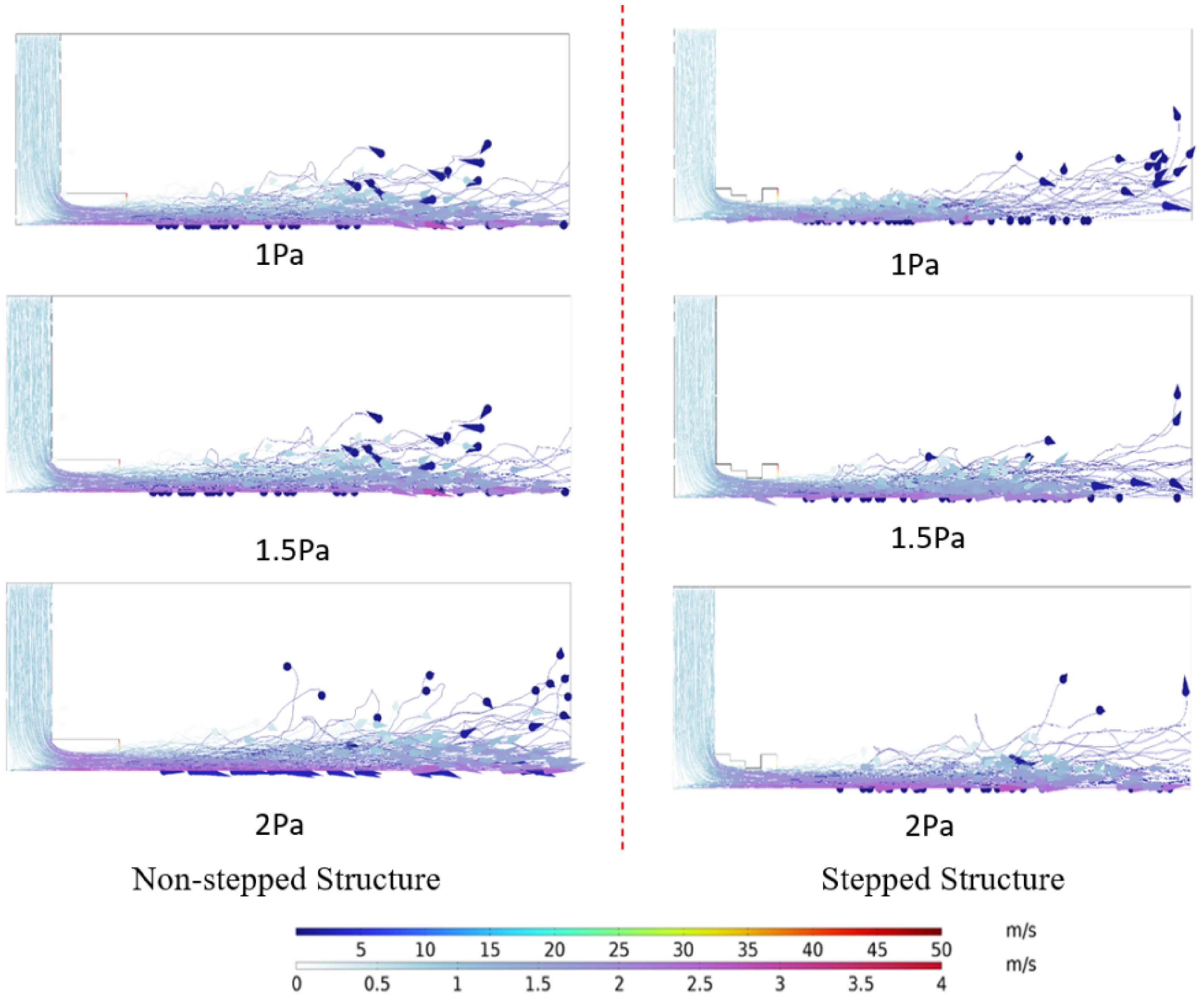
Figure 8.
Simulation diagram of droplet and dust movement.
-
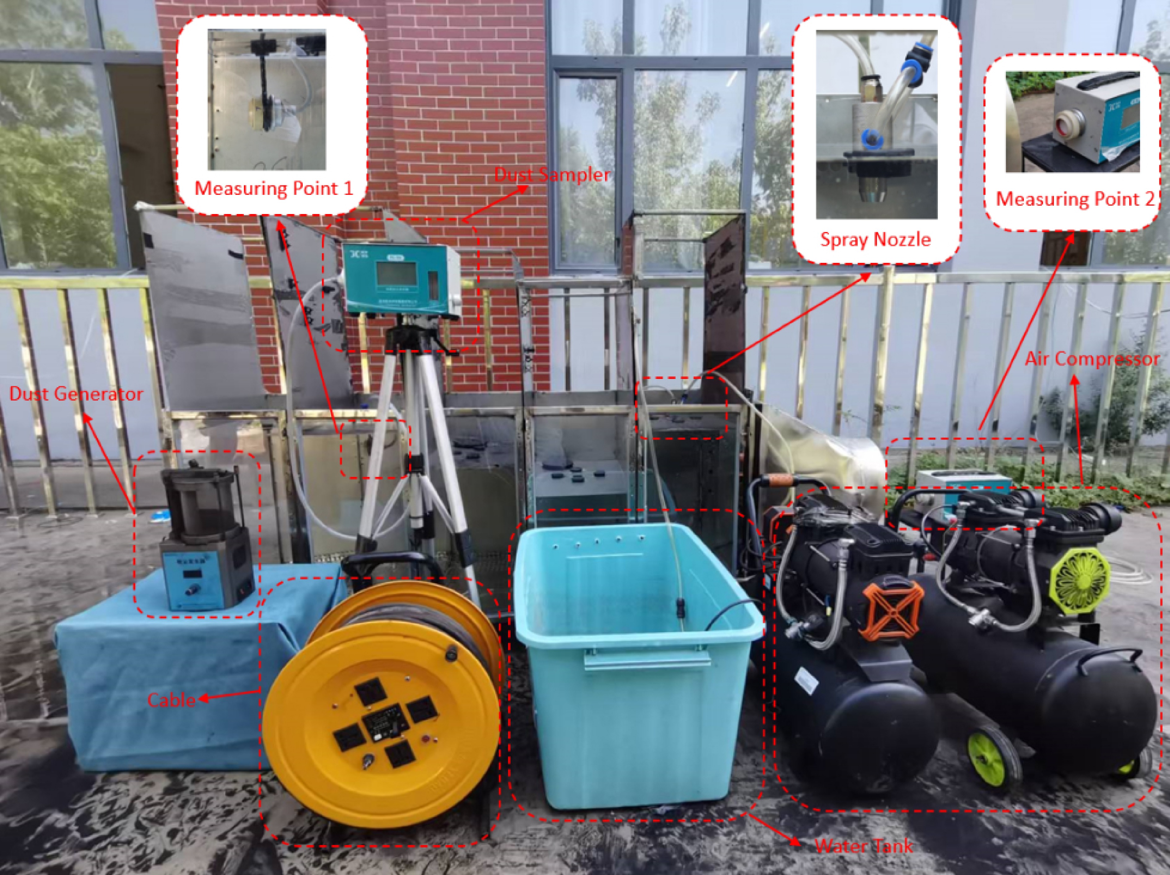
Figure 9.
Experimental bench.
-
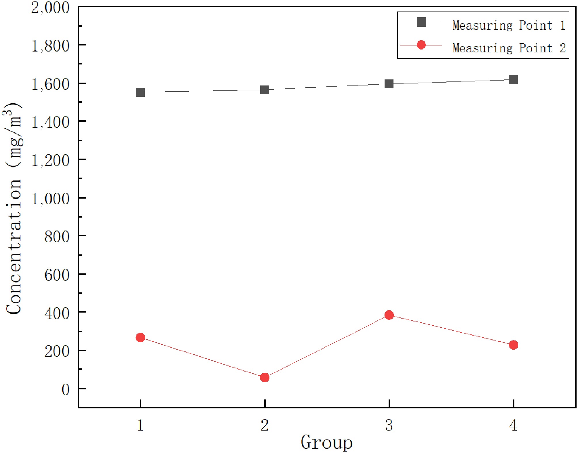
Figure 10.
Measuring point concentration and sampling photos.
-
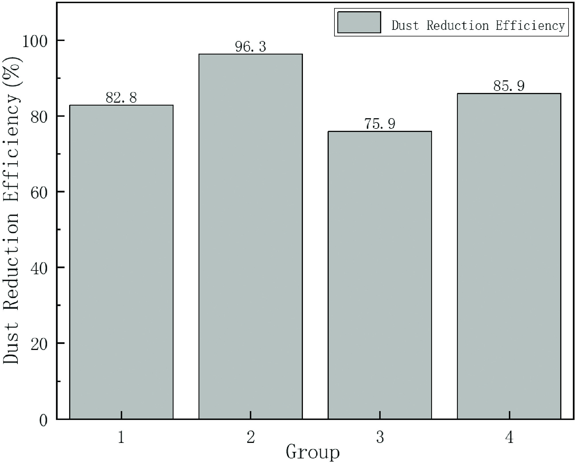
Figure 11.
Dust suppression efficiency.
-
Boundary conditions Parameters Surface tension (N/m) 0.0729 Dust density (kg/m3) 1,650 Pressure (atm) 1 Gas dynamic viscosity (Pa·s) 17.9 × 10⁻⁶ Gas inlet pressure (Pa) 1, 1.5, 2 Adiabatic index 1.4 Droplet density (kg/m3) 1,000 Gas constant (J/kg/K) 287 Liquid dynamic viscosity (Pa·s) 0.001 Initial velocity of fog droplets (m/s) 50 Table 1.
Boundary conditions and parameter settings.
Figures
(11)
Tables
(1)