


-
Coal remains a fundamental energy source in China, and the cleanliness of its transfer processes is critical to the safe and efficient development of the industry. Belt conveyors are the core equipment linking coal production, transportation, and storage, yet the transfer points often generate high dust concentrations due to material impact and airflow disturbances. Dust levels in these areas frequently exceed the 8 mg/m3 occupational exposure limit specified in the Occupational Hazardous Factors Exposure Limits. Such excessive dust not only threatens workers' health and increases the risk of pneumoconiosis, but also poses hazards of explosion, resource loss, and secondary pollution. Therefore, developing high-efficiency dust-suppression technologies tailored to coal-handling conditions is of great practical significance.
A diverse set of dust-control technologies has been established, among which high-pressure micro-mist spraying has become mainstream due to its small droplet size, large contact area, and low water consumption. Its effectiveness has been demonstrated across multiple scenarios. For example, Lian[1] designed a pneumatic high-pressure automatic micro-mist system for belt conveyors, enabling efficient dust suppression via adaptive adjustment of spray parameters; Liu[2] validated its anti-disturbance performance under port environments characterized by strong wind and high humidity; Huang et al.[3] achieved over 80% dust-reduction efficiency in coal-fired power plant transfer stations; and Zhang[4] confirmed its suitability for humid underground conditions. Ma et al.[5] revealed, through numerical simulation, the mechanisms by which micro-mist suppresses coal-dust dispersion, showing that spraying can significantly reduce fine-particle escape even under high-airflow conditions, thus providing theoretical support for spray-based dust control. Meanwhile, to mitigate the strong disturbances caused by impact-induced and induced airflow, Zhang et al.[6] proposed a micro-mist control technology dynamically coupled with coal-flow-induced airflow; Xue et al.[7] demonstrated through gas–water collaborative experiments, that mixed spraying enhances droplet momentum and improves fine-particle capture; Li[8] developed a variable-spray system capable of precise dust suppression under different conveying loads; and Sun & Tao[9] proposed dust-suppression equipment for coal-preparation plants, offering valuable cross-scenario references for transfer-point dust control.
However, the spray alone remains insufficient to fully prevent dust escape. Local enclosure, as the basis for forming a high-concentration dust-control space, plays a decisive role when coupled with micro-mist spraying. Liu et al.[10] showed, via simulation, that reasonable enclosure design can increase internal dust concentration by 30%–50%, significantly improving droplet capture conditions. Jing et al.[11] developed a pneumatic spiral mist-curtain technology that integrates 'local enclosure + mist barrier' and achieved over 90% control efficiency; Liu[12] further verified in field applications that such a synergistic configuration effectively weakens induced airflow and reduces dust dispersion. Jing et al.[13] also demonstrated the applicability of enclosure–mist-curtain combinations in complex tunnel environments from an international perspective.
In recent years, research on structure–airflow-based dust-control technologies has provided important insights for optimizing enclosure design. Based on swirl-induced entrainment theory, Ma et al.[14] proposed a multi-radial swirl-entrainment dust-removal technology that forms an upward entrainment flow using adjustable jet angles and negative-pressure suction; both simulations and experiments showed that an inlet velocity of 8 m/s yields an overall removal efficiency exceeding 95%. Yu et al.[15] found that airflow disturbance at loading stations significantly intensifies dust dispersion and demonstrated that dust-suppression screens can form a low-velocity zone that effectively blocks dust migration. Bao et al.[16] developed a soft-sealing dust-control system that forms a controllable vortex field using upward top airflow and lateral swirl, significantly reducing central dust concentration and extending the effective capture distance. The negative-pressure dust-removal study by Zhang[17] further indicated that particle size and excavation speed greatly influence dust-removal efficiency and provided operating-condition adaptation strategies. Additionally, Jiang et al.[18] systematically reviewed fog-agglomeration and nozzle-atomization mechanisms, highlighting unresolved scientific issues such as unclear agglomeration mechanisms and insufficient nozzle optimization—providing a theoretical foundation for research on spray–structure coupling.
Numerical simulations and experimental testing are essential for improving the performance of 'spray–enclosure' coupled systems. Tong et al.[19], through CFD–DEM simulation, revealed the spatiotemporal distribution characteristics of dust at transfer points, offering guidance for nozzle layout and structural design. Wei[20] validated the reliability of active-spray dust-control mechanisms through combined simulation and field tests. Shi[21] developed an unloading-station micro-mist dust-suppression platform that enables quantitative evaluation of spray response time and control precision. Although significant progress has been made in spray characteristics, enclosure structures, and swirl-field control, systematic mechanistic research on 'multi-stage stepped enclosures + micro-mist spraying' remains insufficient, particularly regarding how multi-stage geometries progressively weaken impact airflow, create stable dust-retention zones, and regulate micro-mist distribution within complex enclosures.
Despite the widespread adoption of the 'local enclosure + micro-mist spraying' approach, its performance at conveyor transfer points—characterized by strong impact and highly disturbed conditions—remains limited by two fundamental mechanistic bottlenecks: (1) The high-velocity impact airflow induced by falling material rapidly expands upon entering the enclosure, penetrating the mist-mixing zone and causing high dust-escape rates. (2) The enclosure interior lacks controllable retention zones, resulting in insufficient dust–mist contact time and low micro-mist capture efficiency. Current studies focus on spray-parameter optimization and enclosure improvement but have not systematically examined how geometric grading can actively shape dust-retention zones and high-efficiency mixing regions. Clear understanding of structure–flow-field–droplet coupling is still lacking.
To address these limitations, this study proposes a multi-stage stepped local-enclosure micro-mist dust-suppression system. Unlike conventional enclosures, this design is based on a re-examination of impact-airflow behavior at transfer points. Through a three-segment stepped configuration—consisting of a descending section, a buffering section, and an ascending section—the structure enables progressive attenuation, segmented dissipation, and directional reconstruction of impact airflow. Numerical simulations show that stable local vortices and retention zones form at each step, prolonging dust residence time within the enclosure. Meanwhile, the stepped structure reshapes droplet distribution, allowing micro-mist to overlap with high-concentration dust regions even under strong disturbances, thereby significantly improving micro-mist utilization. This geometry-induced flow-field shaping and droplet-capture enhancement mechanism constitutes the core innovation distinguishing this study from existing technologies.
-
To investigate the disturbance characteristics of airflow in a coal conveyor transfer point induced by the proposed multi-stage stepped enclosure, a numerical simulation study was conducted to analyze the dust–airflow motion processes. Based on the principles of energy conservation, the ideal-gas state equation, one-dimensional isentropic flow theory, the Navier–Stokes equations, and computational fluid dynamics, the airflow field within the transfer point was simulated using the k–ε turbulence module in COMSOL Multiphysics.
Model type and geometric construction
-
All simulations were performed using a licensed version of COMSOL Multiphysics 6.0. Given that the structural variation of the transfer point along the conveying direction is relatively minor and that the dominant dust–airflow features are concentrated within the vertical cross-section, a two-dimensional (2D) steady-state flow model was adopted to represent the primary internal flow behavior of the enclosed structure.
The geometric model consisted of the material drop port, the multi-stage stepped enclosure, and the outlet passage. The geometry was proportionally scaled to match the configuration of the experimental platform.
Physical interfaces and governing equations
-
The gas phase was treated as an incompressible fluid, coupled with the standard k–ε turbulence model. Dust particles were simulated using the Discrete Phase Model (DPM) via Lagrangian particle tracking. The micro-mist field exerted a weakly coupled influence on the airflow through mass, momentum, and evaporation interactions.
Continuity equation:
$ \nabla \cdot u=0 $ Navier–Stokes momentum equations:
$ \rho (u\cdot \nabla )u=-\nabla p+\mu {\nabla }^{2}u $ Standard k–ε turbulence transport equations:
$ \begin{aligned}\rho (u\cdot \nabla )k&=\nabla \cdot \left[\left(\mu +\dfrac{{\mu }_{t}}{{\sigma }_{k}}\right)\nabla k\right]+{G}_{K}-\rho \varepsilon \\ \rho (u\cdot \nabla )\varepsilon &=\nabla \cdot \left[\left(\mu +\dfrac{{\mu }_{t}}{\sigma \varepsilon }\right)\nabla \varepsilon \right]+{C}_{l\varepsilon }{G}_{k}\dfrac{\varepsilon }{k}-{C}_{2\varepsilon }\rho \dfrac{{\varepsilon }^{2}}{k} \end{aligned} $ Dust particle motion equation (DPM):
$ {m}_{p}\dfrac{d{v}_{p}}{dt}={F}_{D}+{m}_{p}g $ The particle drag force was calculated using the Schiller–Naumann correlation.
Mesh generation
-
Mesh quality is fundamental to ensuring the accuracy and reliability of the numerical results. As shown in Fig. 1, the non-stepped model, owing to its relatively simple geometry, exhibits a uniform and continuous mesh distribution. In contrast, the stepped model has significantly higher geometric complexity in regions with abrupt step transitions; thus, local mesh refinement and adaptive adjustment were applied to accurately capture the geometric variations. This refinement provides the necessary spatial resolution to resolve the airflow disturbances and dust-motion behaviors induced by the stepped structure.
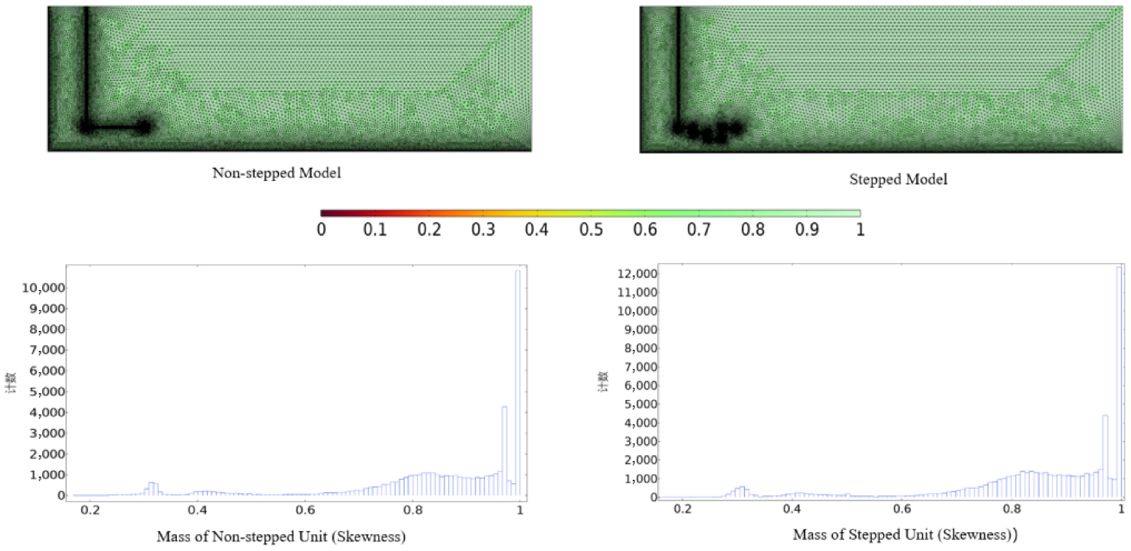
Figure 1.
Mesh generation and element quality.
The element-quality histogram indicates that the non-stepped model maintains highly concentrated, high-quality mesh elements due to its regular geometry. Although the stepped model displays slight variability in mesh quality caused by its complex structure, the vast majority of elements still fall within the high-quality range, and local quality fluctuations remain within acceptable engineering limits. This demonstrates that the adopted meshing strategy effectively balances geometric fidelity and computational stability.
Overall, both models achieved high mesh quality, providing a reliable discrete foundation for simulating the internal airflow organization, dust migration, and dust–mist interactions within the conveyor transfer point. This ensures that the numerical results accurately reflect the essential physical characteristics of the system and establishes a robust computational basis for further investigation into the dust-suppression mechanisms of the multi-stage stepped enclosure.
Boundary conditions and parameter settings
-
Boundary conditions and parameter settings are as shown in Table 1. Additionally, the airflow pressure, dust density, initial droplet velocity, ambient humidity, and other parameters employed in the numerical simulations were derived from on-site investigations of actual conveyor transfer points and the measured conditions of the experimental platform. The inlet airflow pressure (1–2 Pa) corresponds to the typical dynamic pressure range of induced airflow generated during material falling, and the resulting induced-air velocity matches the natural airflow produced by coal-flow impact. The coal-dust density (1,650 kg/m3) was obtained from measured data of bituminous coal in the Yulin mining area, and a particle-size distribution of <50 µm was selected to represent the fine, high-risk respirable dust fraction commonly found at transfer points. The initial droplet velocity (50 m/s) was determined according to the performance parameters of the supersonic coaxial nozzle used in the tests and verified through experimental measurements to match the momentum level of micro-mist nozzles typically applied in field conditions.
Table 1. Boundary conditions and parameter settings.
Boundary conditions Parameters Surface tension (N/m) 0.0729 Dust density (kg/m3) 1,650 Pressure (atm) 1 Gas dynamic viscosity (Pa·s) 17.9 × 10⁻⁶ Gas inlet pressure (Pa) 1, 1.5, 2 Adiabatic index 1.4 Droplet density (kg/m3) 1,000 Gas constant (J/kg/K) 287 Liquid dynamic viscosity (Pa·s) 0.001 Initial velocity of fog droplets (m/s) 50 Therefore, all parameters adopted in the simulations fall within the realistic engineering range of conveyor transfer points and are capable of representing typical operational conditions, providing a robust physical foundation for subsequent comparative analyses.
Flow-field validation based on induced-air velocity
-
To further verify the capability of the numerical model in capturing the internal flow characteristics of the stepped enclosure, the induced-air velocity was selected as the key comparison metric for quantitative validation between simulation and experiment. Induced airflow is the dominant driving force during material dropping; its magnitude and attenuation behavior directly determine the dust-dispersion range and the positioning of the spray action zone. Thus, it serves as a critical physical indicator for evaluating model reliability.
In the experiment, an anemometer was placed along the axis of the dropping tube to measure the induced-air velocity distribution at various heights. Simulation data were extracted at the corresponding positions for comparison. Results show that, under non-spray conditions, the peak induced-air velocity within the stepped structure occurs near the leading edge of the first step. The measured velocity was approximately 3.48 m/s, while the simulated value was 3.32 m/s, yielding a relative error of 4.6%. In the buffer region near the second step, the measured velocity was about 1.87 m/s, and the simulation predicted 1.79 m/s, with an error of 4.3%. In the non-stepped structure, the induced airflow exhibited a clear penetrating-flow pattern, with a measured mainstream velocity of approximately 3.95 m/s and a simulated value of 3.76 m/s, corresponding to an error of 4.8%. These comparisons indicate that the model accurately reproduces peak locations, attenuation rates, and overall flow trends of induced airflow.
Furthermore, experiments revealed pronounced local recirculation and stagnation zones at the leading edges of each step, and the simulated positions and strengths of these recirculation cells closely matched the measurements. For the first step, the recirculation-core center was located 35–45 mm away from the wall, with simulation–experiment deviations of less than 6 mm. The second-step recirculation region was slightly smaller but maintained the same overall pattern. This consistency demonstrates the model's strong capability in capturing vortex structures.
Overall, the validation errors associated with induced-air velocity remained below 5%, and the agreement in peak locations, attenuation laws, and recirculation patterns was high. These results confirm that the numerical model reliably represents the flow mechanisms within the stepped enclosure and is suitable for subsequent analyses of droplet dispersion and dust-transport mechanisms.
Model limitations
-
The main limitations of the present model include: (1) the 2D configuration cannot fully represent three-dimensional lateral flow; (2) droplet evaporation and coalescence were simplified; (3) variations in real dust morphology and wettability were not fully incorporated; and (4) dynamic fluctuations in underground airflow and humidity were not considered in the boundary conditions. Therefore, while the simulation results effectively reveal the dominant mechanisms governing impact-airflow attenuation, recirculation formation, and spray distribution in the stepped structure, experimental data remain essential for model calibration and comprehensive interpretation.
Results analysis
-
For the non-stepped structure (Fig. 2), as the pressure increases from 1 to 1.5 Pa and subsequently to 2 Pa, the variation in streamline colors becomes more pronounced. The regions with high flow velocity (e.g., red and orange areas) gradually expand and become more dispersed. This indicates that the airflow velocity inside the non-stepped structure increases with rising pressure, accompanied by enhanced turbulence. Consequently, the airflow tends to diffuse more easily into surrounding regions.
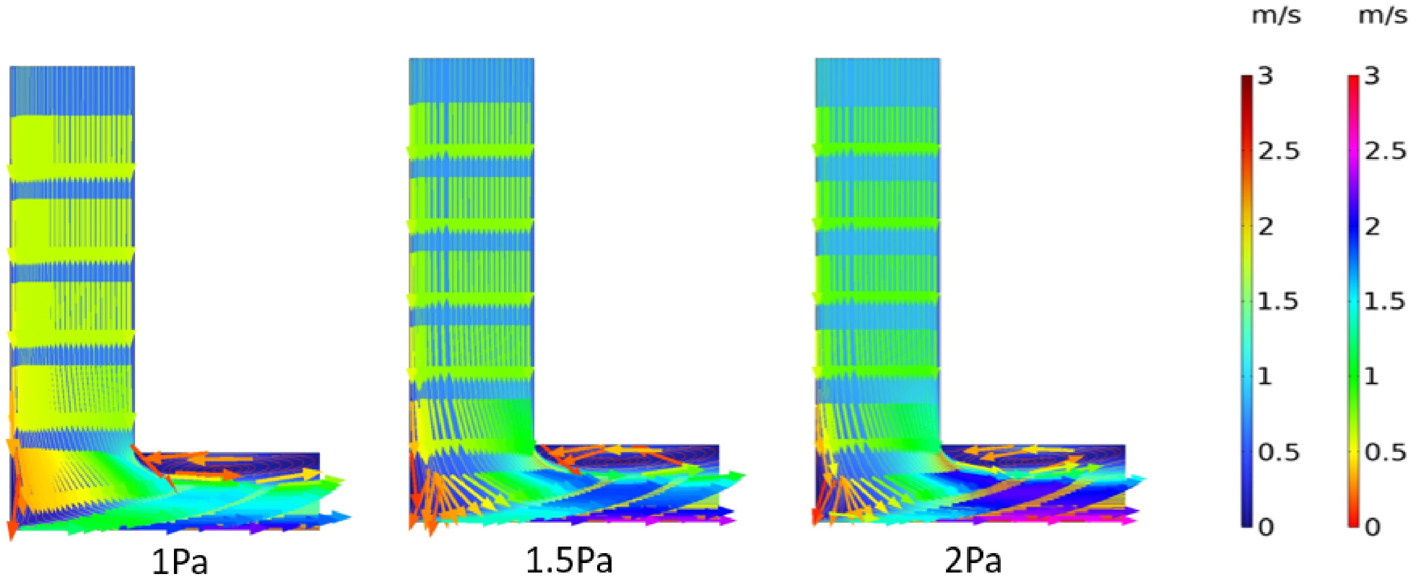
Figure 2.
Streamline diagram of the non-step structure.
For the stepped structure (Fig. 3), during the pressure increase from 1 to 2 Pa, the distribution of streamline colors remains relatively concentrated. High-velocity regions are mainly confined to the vicinity of the step. Although the high-velocity area exhibits some degree of expansion as the pressure increases, it remains largely restricted to the region influenced by the stepped geometry. This suggests that airflow in the stepped structure maintains stronger directionality and concentration.
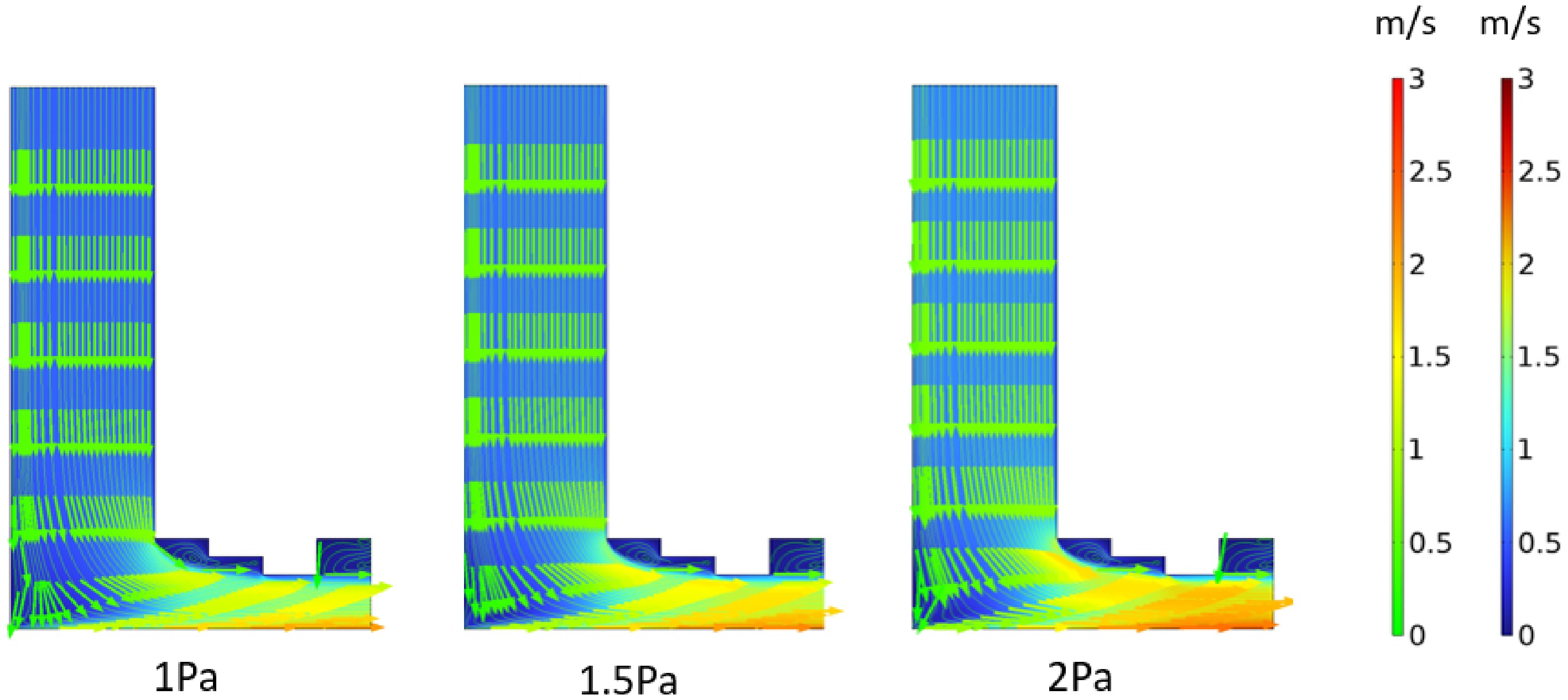
Figure 3.
Streamline diagram of the step structure.
From the perspective of airflow distribution range, the non-stepped structure exhibits a broader distribution of high-velocity regions under different pressures. At 2 Pa in particular, these regions extend further downstream. In contrast, under the stepped structure, high-velocity regions consistently remain concentrated near the step, with a noticeably smaller distribution range compared with the non-stepped configuration.
Regarding airflow stability, the streamlines within the non-stepped structure become increasingly disordered with higher pressure, showing significant changes in streamline patterns. In comparison, the stepped structure maintains a more stable streamline pattern; despite the pressure increase, the overall distribution remains relatively unchanged. This demonstrates that the stepped design provides effective constraint on airflow motion and enhances its stability.
In summary, the stepped structure effectively constrains airflow motion, keeping high-velocity regions localized under varying pressure conditions. This reduces the diffusion of airflow into surrounding areas and improves the stability of airflow transport. Such characteristics are conducive to dust control and can enhance the particle-capture efficiency of subsequent micro-mist dust-suppression measures.
The velocity field distribution is as shown in Fig. 4. For the non-step structure under pressures of 1, 1.5, and 2 Pa, as pressure increases, the range of color regions representing high velocity gradually expands and becomes more dispersed. The airflow velocity increases significantly with strong diffusivity, which easily drives extensive dust diffusion. In contrast, for the step structure under different pressures, high-velocity regions are mainly concentrated in local areas near the steps. When pressure increases, the expansion extent of high-velocity regions is much smaller than that of the non-step structure. The airflow velocity distribution is more concentrated, exerting a good restraining effect on airflow, limiting excessive airflow diffusion, and being more conducive to dust control.
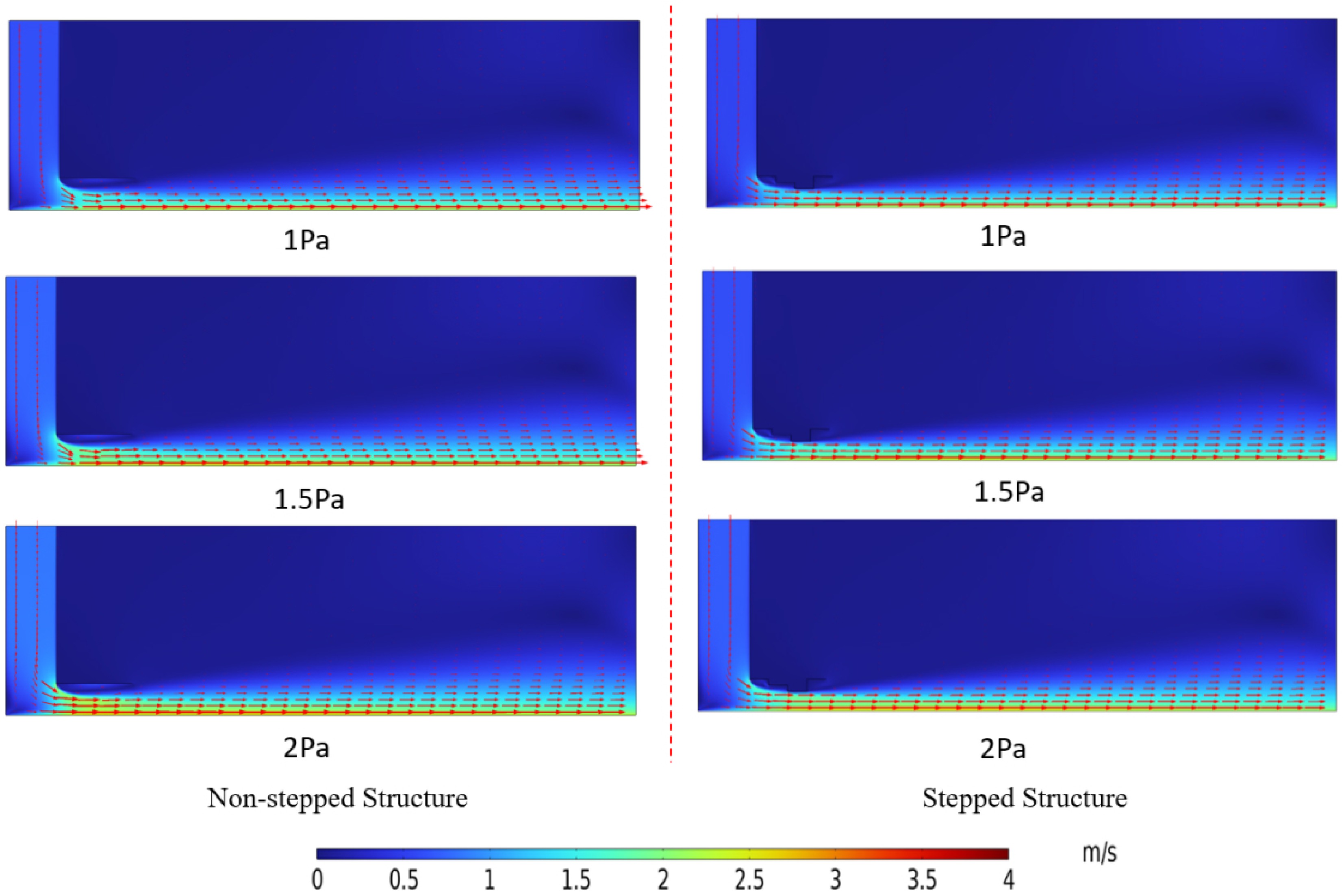
Figure 4.
Velocity field distribution diagram.
As can be seen in Fig. 5, in the vorticity diagram of the non-step structure, as the pressure increases from 1 to 2 Pa, the concentration degree of the yellow regions at the corners gradually deepens, and their range also expands to a certain extent; for the step structure, under different pressures, the yellow vorticity is mainly concentrated near the steps. The impact of pressure changes on the concentrated regions of yellow vorticity is relatively mild, and the range of these regions is smaller than that of the non-step structure.
In the non-step structure, the yellow vorticity exhibits a high concentration degree and a wide distribution range. Pressure changes easily cause the yellow vorticity to diffuse extensively at the corners and their surrounding areas; in the step structure, the number of vortices increases and is concentrated in the local areas around the steps. This structure can better restrict the diffusion of yellow vorticity, rendering the distribution of yellow vorticity more controllable.
The step structure can effectively constrain the concentration and diffusion of yellow vorticity, concentrating it more in the local areas around the steps, reducing disturbances to the surrounding airflow. This facilitates stabilizing airflow movement to control dust diffusion and improves the effectiveness of dust management.
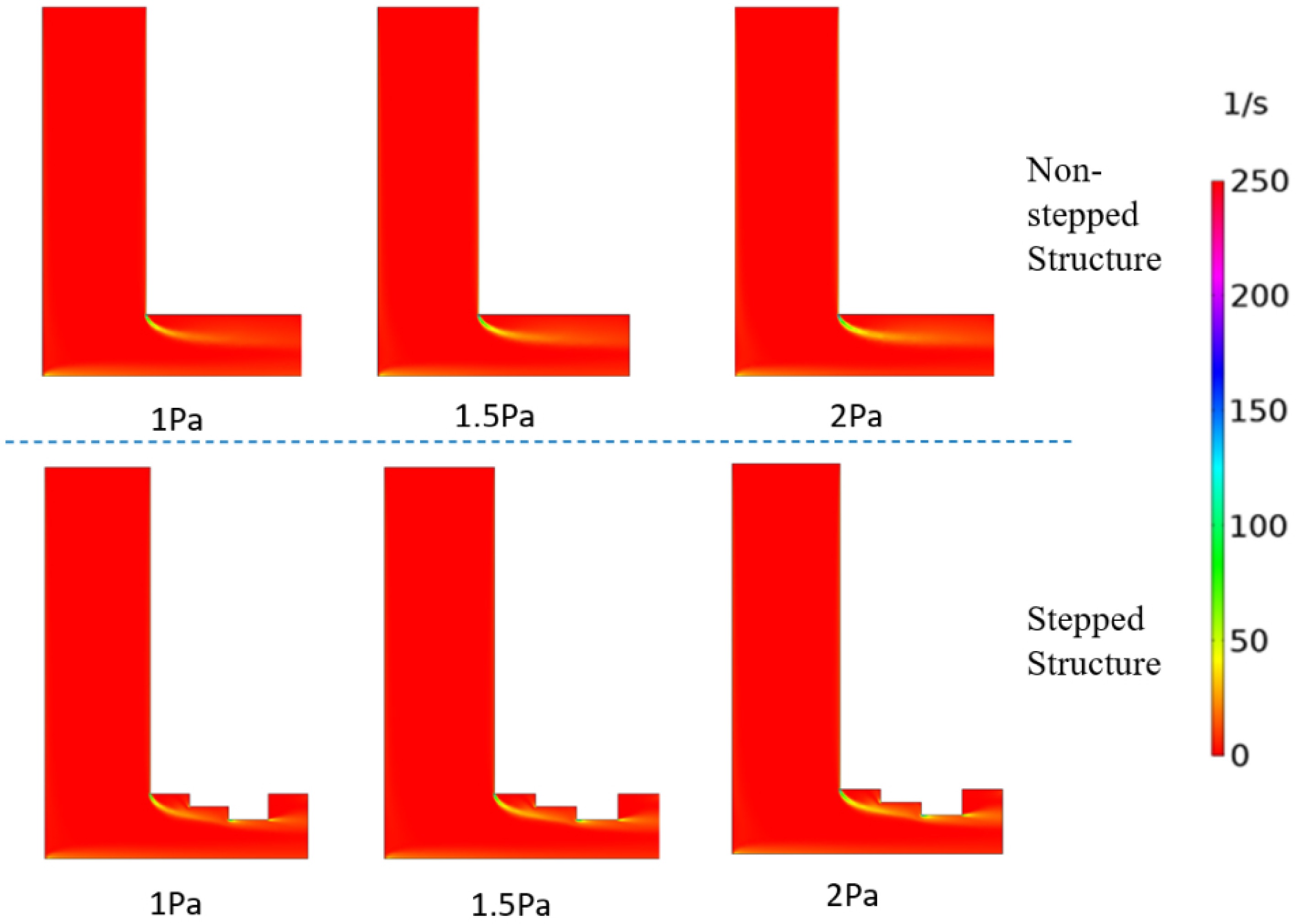
Figure 5.
Vorticity diagram.
As can be seen from Fig. 6, as the pressure increases from 1 to 1.5 Pa, and then to 2 Pa, the dust diffusion range gradually expands, and the dust movement velocity accelerates step by step. At the same moment, the higher the pressure, the more significant the dust diffusion from the left to the right and surrounding areas. In the later stage (e.g., at 8 s), under high pressure (2 Pa), the dust almost covers a wider area, while under low pressure (1 Pa), the dust diffusion is relatively limited.
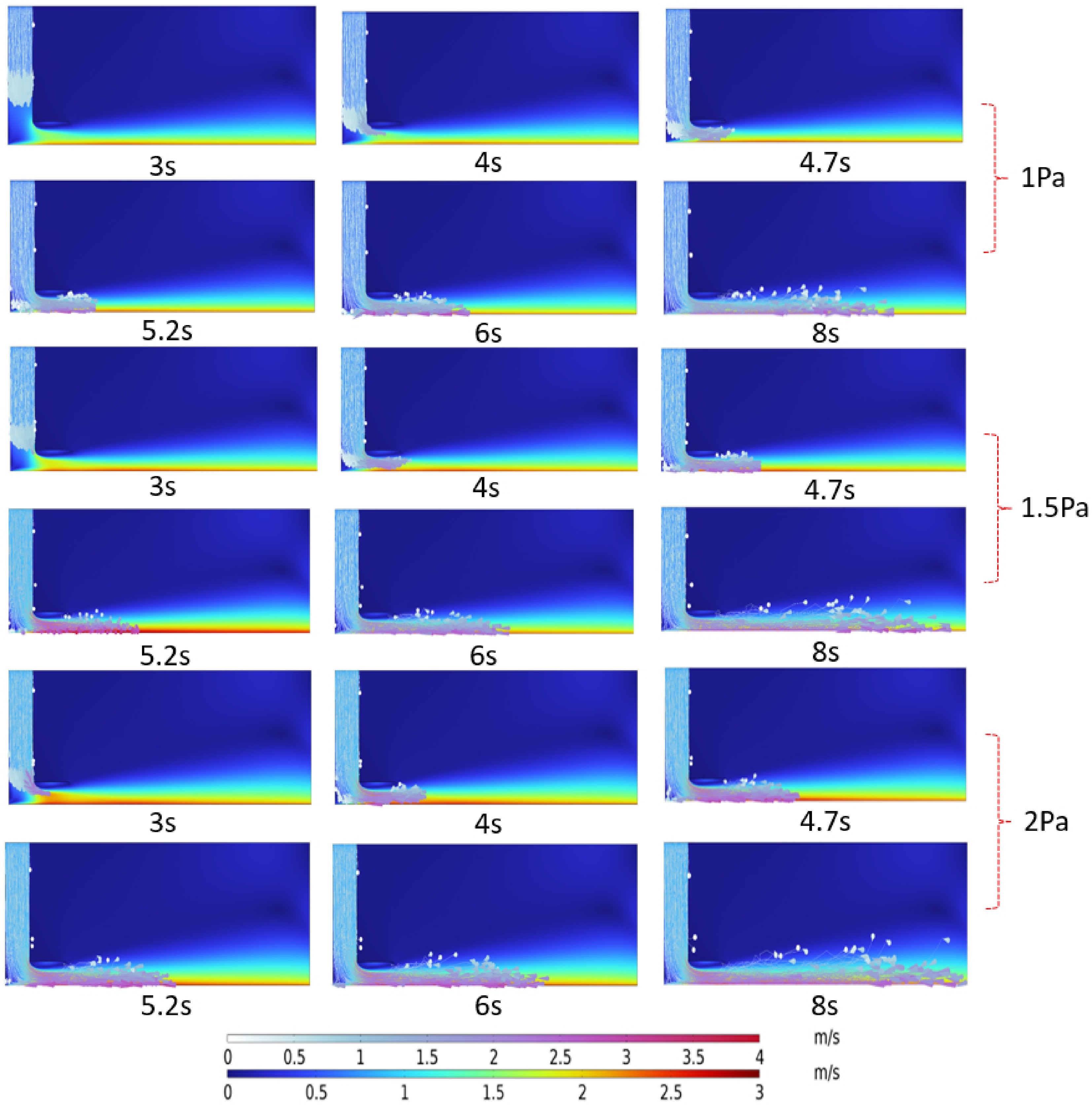
Figure 6.
Dust movement diagram of the non-step structure.
From Fig. 7, under pressures of 1, 1.5, and 2 Pa, the overall dust movement is gentler, with the diffusion range remaining relatively small and mainly concentrated in the areas near the step structure. Although the dust diffusion shows an increasing trend as pressure rises, it is still well confined to local areas, with no large-scale and rapid spread observed.
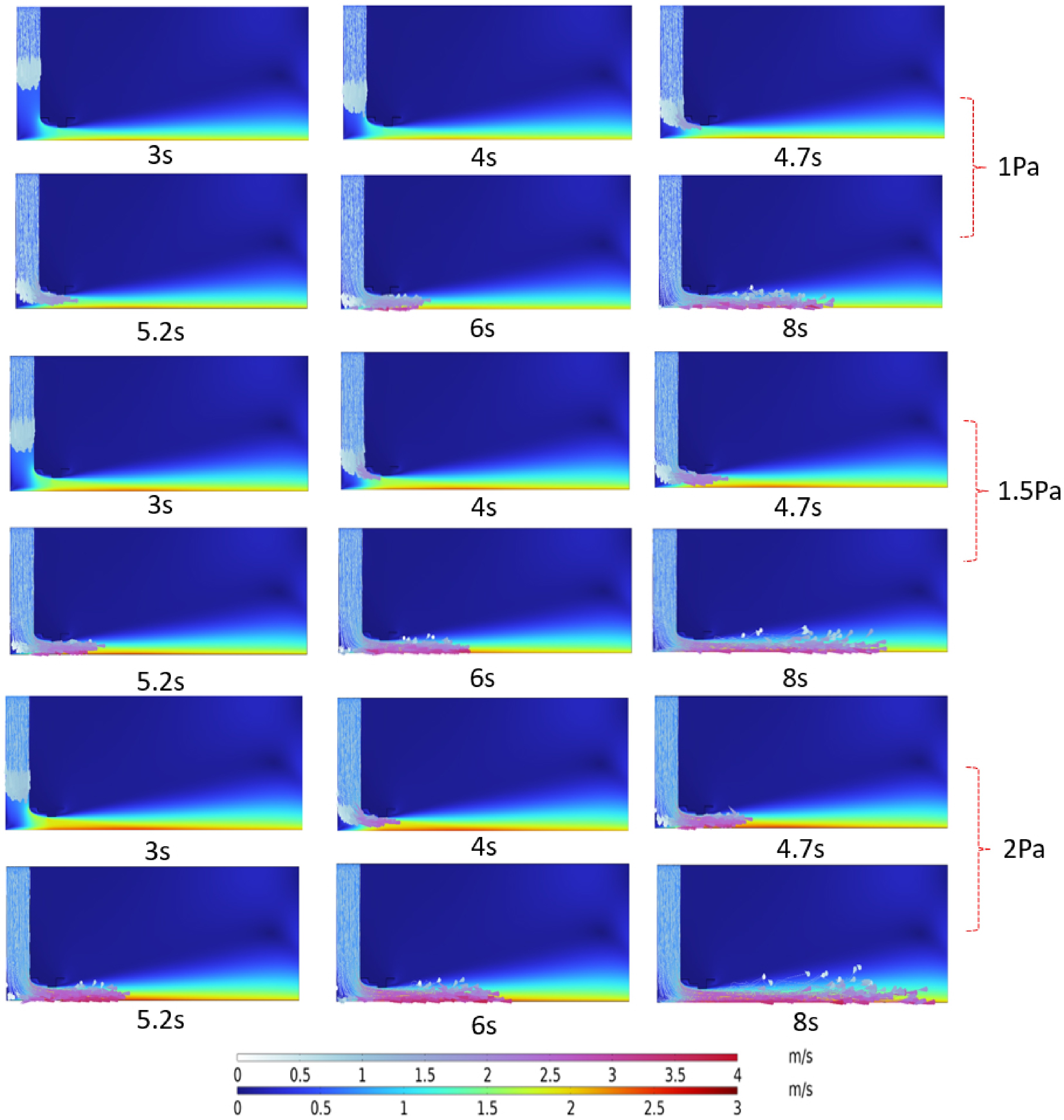
Figure 7.
Dust movement diagram of the step structure.
A comparison of Figs 6 and 7 reveals that in the non-step structure, the dust diffusion range is wide, and it expands significantly as pressure increases; in the step structure, the dust diffusion range is significantly restricted, mainly concentrated around the steps, and the impact of pressure on its diffusion range is smaller than that in the non-step structure. The dust in the non-step structure moves at a high velocity and is scattered in distribution; the step structure, through its stepped design, inhibits dust movement, reducing the dust velocity and making it more likely to concentrate in the step areas.
Therefore, the step structure can effectively limit the dust diffusion range, reduce the dust movement velocity, and promote dust concentration. It enhances the dust control effect, adapts to different pressure conditions, and is more conducive to dust management at coal conveyor transfer points.
As shown in Fig. 8, in the non-step structure, as the pressure increases from 1 to 1.5 Pa, and then to 2 Pa, the amount of visible dust gradually increases and becomes more dispersed in distribution; in the step structure, under different pressures, the amount of dust is relatively smaller, with stronger concentration.
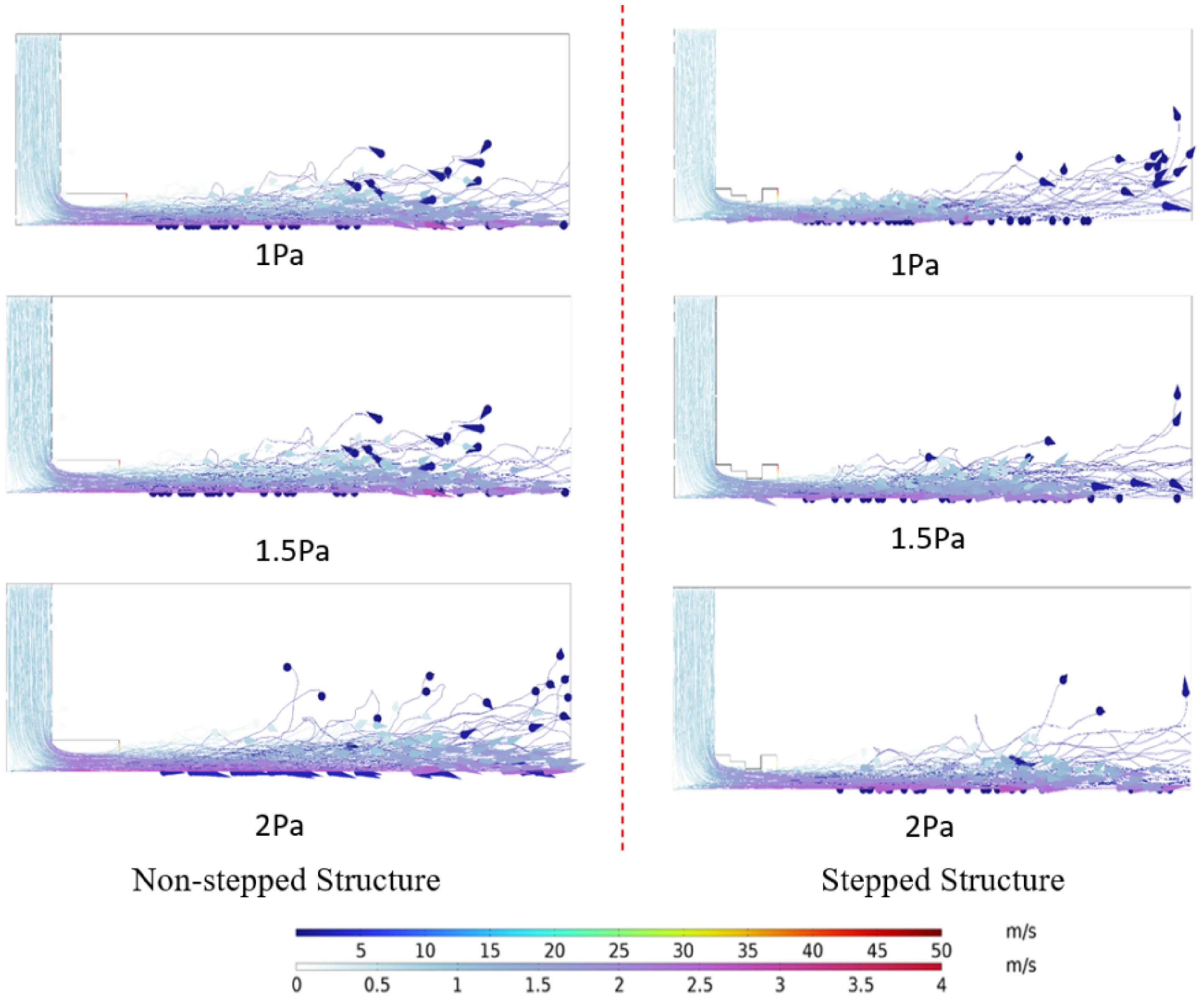
Figure 8.
Simulation diagram of droplet and dust movement.
-
To ensure the scientific validity and reproducibility of the experimental results, unified settings were adopted for the experimental conditions, dust properties, and environmental control. The dust used in the experiments was collected from a fully mechanized mining face in Yulin, Shaanxi Province, China. The coal type was bituminous coal (industrial analysis: Mad = 0.82%, Aad = 7.32%, Vad = 21.56%, Vdaf = 23.89%). After sieving treatment, coal dust with a particle size smaller than 50 μm was selected as the experimental sample to more accurately reflect the real diffusion and capture characteristics of respirable fine particles in the transfer-point region. A DFS-3 dust generator (Kexing Applied Technology Institute, Northeastern University) was used as the dust dispersion device. For each experiment, 50 g of the sieved fine coal dust was uniformly added to the generator to ensure consistent initial dust mass across all test conditions, eliminating experimental bias caused by variations in the dust source.
The experiments were conducted under natural indoor conditions, with the temperature maintained at approximately 22 °C and relative humidity at 50%. Environmental changes were continuously monitored using a digital temperature–humidity meter to avoid the influence of humidity and temperature fluctuations on droplet evaporation rate, coal-dust wettability, and particle transport behavior. The dust-dispersion airflow rate and dusting duration were kept identical across all tests. The dusting time was set to 10 s, and the airflow rate was matched to the boundary conditions used in the numerical simulations to ensure comparability between the simulated and experimental results. The spray pressure was maintained at 0.3 MPa, within the stable operating range of the nozzle, to avoid instability of the spray field affecting dust-suppression performance. Under this condition, the droplet diameter corresponding to a droplet number fraction of 50% was 7.64 μm[22].
To improve the reliability of the experimental data, each working condition was tested in three independent repeated experiments, and the average value was used as the final result. Errors were strictly controlled during sampling: the flow variation before and after dust sampling did not exceed 3%, the weighing error of the sampling filter membrane was less than 0.01 mg, and the relative standard deviation (RSD) of repeated tests was controlled within 5%, meeting the requirements of the mine-dust measurement standards MT/T 878 and AQ 1029. Through the above control measures, the comparative evaluation of the dust-suppression performance of stepped and non-stepped structures under spraying and non-spraying conditions was ensured to be scientifically rigorous, stable, and reproducible.
The experimental platform for staged stepped local confined micro-mist dust suppression is shown in Fig. 9. The instruments and equipment used in this platform include dust curtains, dust generators, cables, mining dust samplers, water storage tanks, coaxial atomizing nozzles, air compressors, iron stands, and analytical balances (with a precision of 0.1 mg). For the construction of the stepped test bench, the height of the first step is 50 cm, the second step is 40 cm, the third step is 30 cm, the fourth step is 20 cm, and the fifth step is 30 cm.
The construction of the non-stepped test bench, with the height of each step uniformly set as 50 cm.
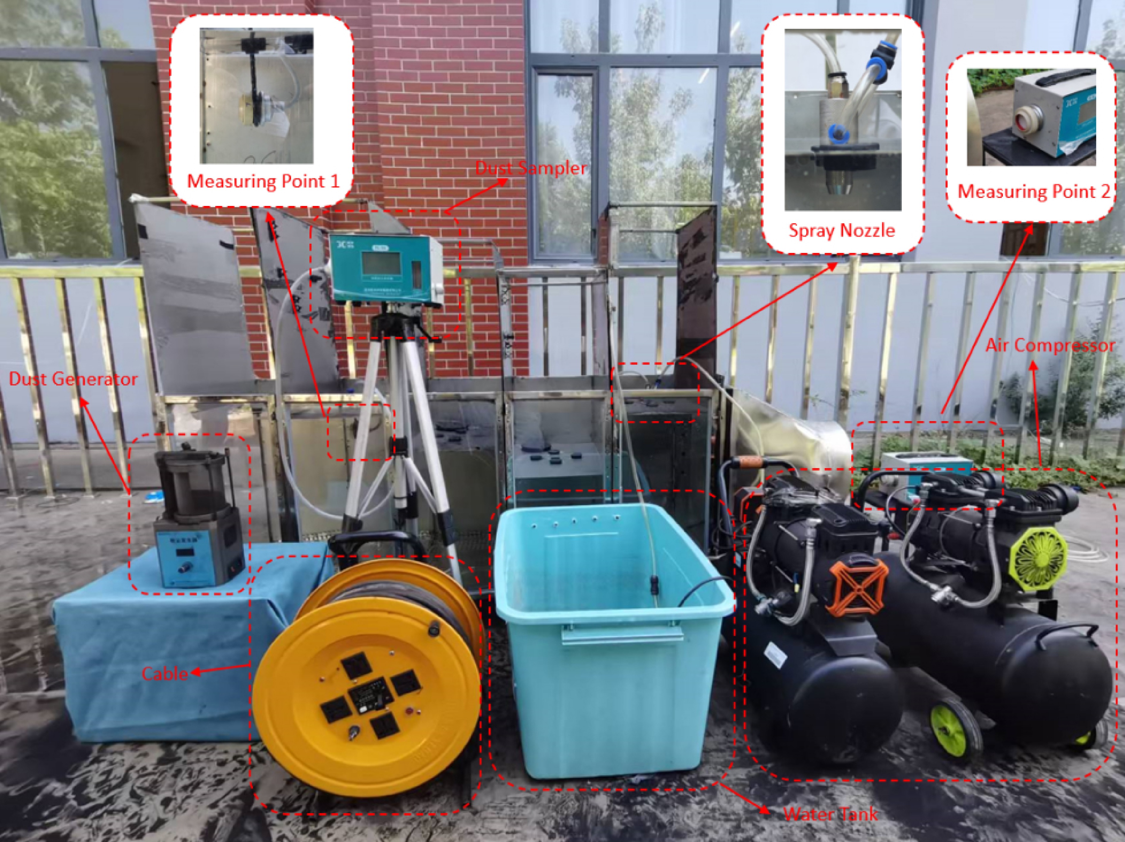
Figure 9.
Experimental bench.
Experimental procedures
-
Stepped local confined micro-mist dust suppression experiment:
(1) Without turning on the spray, dust is generated with the same air flow rate for 20 s. The mass of dust generated each time is kept consistent to ensure uniform dust concentration.
(2) Simultaneously, sampling is conducted using Dust Samplers No. 1 and No. 2 for 20 s. After the experiment, the weight of the sampling membrane is measured, and the data is recorded. This set is designated as the first group of experiments.
(3) After a 15-min interval, the spray is turned on, and dust is generated with the same air flow rate for 20 s. Simultaneously, sampling is conducted using Dust Samplers No. 1 and No. 2 for 20 s. After the experiment, the weight of the sampling membrane is measured, and the data is recorded, designated as the second group of experiments.
Non-stepped local confined micro-mist dust suppression experiment:
(1) The test bench is modified to a non-stepped type. Without turning on the spray, dust is generated with the same air flow rate for 20 s. The mass of dust generated each time is kept consistent to ensure uniform dust concentration.
(2) Simultaneously, sampling is conducted using Dust Samplers No. 1 and No. 2 for 20 s. After the experiment, the weight of the sampling membrane is measured, and the data is recorded. This set is designated as the third group of experiments.
(3) After a 15-min interval, the spray is turned on, and dust is generated with the same air flow rate for 20 s. Simultaneously, sampling is conducted using Dust Samplers No. 1 and No. 2 for 20 s. After the experiment, the weight of the sampling membrane is measured, and the data is recorded, designated as the fourth group of experiments.
Experimental results
-
The experimental results are shown in Figs 10 and 11. Under non-spraying conditions, the dust concentrations at Measurement Point 1 for both the stepped and non-stepped structures remain at relatively high levels, with only minor differences between the two. This indicates that a large amount of dust is present in both structural configurations when spraying is not applied.
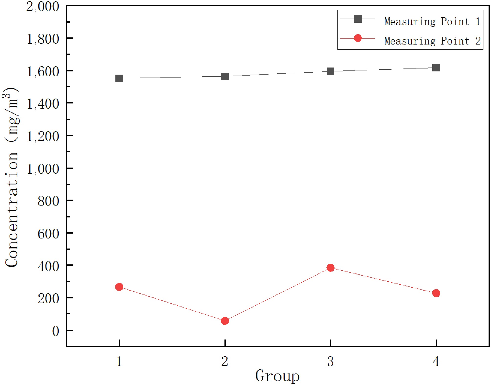
Figure 10.
Measuring point concentration and sampling photos.
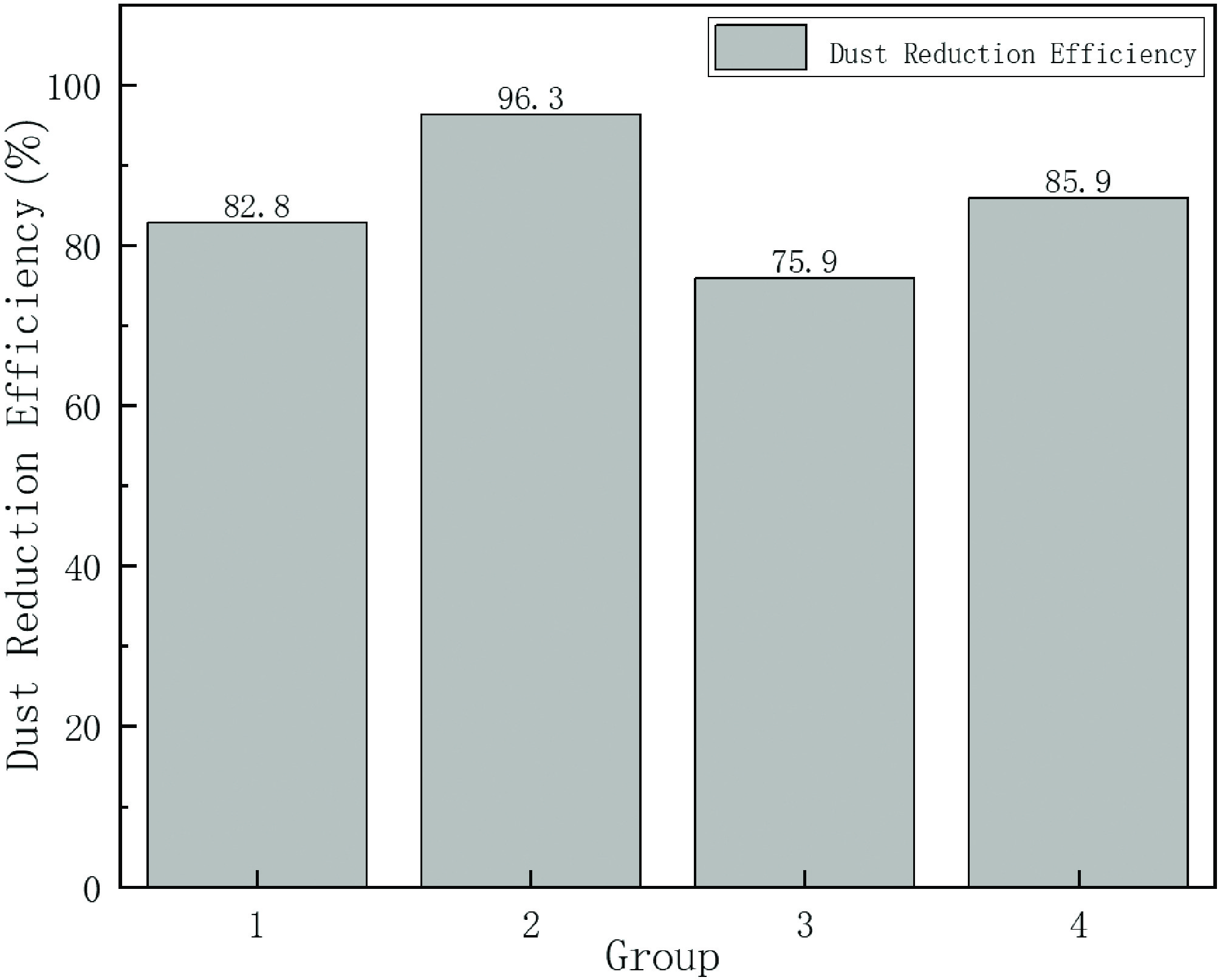
Figure 11.
Dust suppression efficiency.
Under spraying conditions, the stepped structure exhibits the highest dust-reduction efficiency, reaching approximately 96%. The dust concentration at Measurement Point 2 decreases substantially, with the color becoming markedly lighter compared with that in the non-spraying stepped group. In contrast, the non-stepped structure achieves a dust-reduction efficiency of approximately 86%, showing a weaker reduction in dust concentration and a lower suppression efficiency than the stepped structure; the color at Measurement Point 2 also appears darker.
The dust-control advantage of the stepped structure is not merely due to a reduction in airflow velocity, but stems from its substantial modification of the internal airflow organization within the enclosed chamber. Combined with the simulation results, it is observed that the falling airflow induces local vortices and weak recirculation zones at each step, forming several mutually independent vortex regions along the stepped direction. Because the vortex cores exhibit large velocity gradients and relatively low pressure, dust particles entering these regions are entrained and circulate along the vortex paths, significantly extending their residence time within the chamber. Meanwhile, the shear layers formed at the vortex boundaries segment the main flow into several localized regions, effectively blocking the direct upward transport pathway of dust carried by high-speed airflow.
For spray droplets, the vortex-induced local retention zones maintain a stable droplet distribution within the stepped cavities rather than allowing droplets to be rapidly transported by the main airflow. The 'entrainment zones' for dust, and the 'retention zones' for droplets show a high degree of spatial overlap. This airflow-guided process—characterized by flow segmentation, the formation of retention regions, and spatial superposition—driven by the stepped geometry is the fundamental mechanism responsible for the significantly enhanced dust-capture efficiency of the stepped structure.
-
The graded stepped local-enclosure micro-mist dust suppression system demonstrates excellent dust-control performance under both simulation and laboratory conditions. However, its effectiveness in complex industrial environments is influenced by multiple external factors, necessitating further evaluation of its applicability and potential limitations.
Influence of changes in ventilation conditions
-
The ventilation airflow at underground transfer points typically fluctuates with operating conditions and roadway configurations. Strong ventilation may weaken the stepped structure's capability to segment the airflow, destabilizing the local vortex structures and thereby affecting dust retention within the enclosed chamber as well as the uniform suspension of micro-mist droplets. Therefore, the system is more suitable for scenarios with relatively stable ventilation conditions. In environments with high airflow intensity, structural flow-control capability may be enhanced by optimizing step dimensions, increasing the enclosure coverage, or introducing flow-guiding components.
Influence of ambient humidity on micro-mist behavior
-
Humidity is a key factor governing droplet size, evaporation rate, and suspension time. Under high-humidity conditions, droplets readily coalesce, resulting in larger sizes and accelerated settling; under low-humidity conditions, rapid evaporation may reduce droplet wetting and agglomeration efficiency. To ensure stable system performance across varying humidity levels, spray pressure may be adjusted according to real-time humidity, different nozzle types may be selected, or dual-fluid atomization technology may be adopted to maintain droplet uniformity and effective coverage.
Influence of spatial constraints on equipment layout
-
Space at actual transfer points is commonly limited by chute structures, support equipment, and passageways. If step height or spacing is restricted, the formation of vortices and retention zones may be weakened, reducing the overall system performance. For space-constrained scenarios, modular or adjustable stepped structures can be deployed to ensure flexible adaptation to different roadway cross-sections and equipment layouts.
Adaptation challenges caused by dust property variations
-
Dust properties—including particle-size distribution, wettability, and surface characteristics—vary significantly across coal types and working conditions. Such differences may influence particle retention and micro-mist capture efficiency. For finer or more hydrophobic dust, spraying energy may be increased, finer droplets may be employed, or coagulation-assisted techniques may be introduced to enhance dust-capture effectiveness.
Engineering optimization strategies
-
To maintain stable system performance under complex conditions, several measures may be implemented according to site-specific factors: adjust spray parameters based on real-time ventilation and humidity; use flow-guiding plates or local sealing components to stabilize the stepped-region flow field; select specialized nozzles and spraying schemes according to dust characteristics; and deploy adjustable step modules in space-limited areas to achieve localized optimization. These strategies can effectively improve the adaptability and reliability of the system across diverse working conditions.
Overall, the graded stepped local-enclosure micro-mist dust suppression system possesses strong potential for engineering application. Nevertheless, successful implementation in real industrial settings requires targeted optimization based on ventilation, humidity, spatial layout, and dust characteristics to ensure sustained and effective dust-control performance under variable operating conditions.
-
Based on the simulation and experimental investigation of the graded stepped local-enclosure micro-mist dust suppression system for belt-to-belt coal transfer points, the following conclusions are drawn:
(1) The stepped structure exhibits significant advantages in airflow organization.
The descending-section steps induce local vortices and attenuate the impact airflow generated by falling coal, thereby reducing the effective flow cross-section and limiting the disturbance range. The ascending section further slows the airflow and enhances its controllability, providing a more stable flow environment conducive to particle capture. The combined effect of local enclosure increases the probability of interaction between droplets and dust particles.
(2) The stepped structure outperforms the non-stepped structure in dust-motion control.
Under various pressure conditions, the stepped geometry effectively reduces dust particle velocity and restricts dust-dispersion extent, enabling dust to accumulate and remain within the chamber. This enhances micro-mist capture efficiency and reduces dust escape, demonstrating strong structural adaptability and stable control performance across different operating conditions.
(3) A clear synergistic dust-suppression mechanism exists between the stepped structure and micro-mist.
First, the local vortices and retention zones induced by each step substantially extend the residence time of dust particles within the enclosed chamber, promoting spatial 'retention–accumulation', which increases the probability of effective dust–droplet collisions.
Second, the step-induced attenuation and redirection of airflow enable fine droplets to remain stably suspended within the chamber and spatially overlap with high-concentration dust regions. This enhances droplet utilization efficiency. Together, these synergistic mechanisms physically explain the significantly higher dust-suppression performance of the stepped structure compared to the non-stepped configuration.
(4) Integrating simulation and experimental results, the proposed graded stepped local-enclosure micro-mist system markedly improves dust-control performance at transfer points.
The system achieves a coupled enhancement of 'structural optimization–flow-field regulation–micro-mist reinforcement', effectively suppressing dust dispersion under high-impact disturbed conditions. It provides a structured and engineering-feasible solution for dust mitigation at belt transfer points and holds substantial potential for wider industrial application.
This study was supported by the relevant experimental platforms and testing equipment, for which the authors are sincerely grateful. We also wish to thank the reviewers for their valuable comments and suggestions, which have significantly improved the quality of this paper. Our appreciation is extended to the colleagues who assisted with the experimental setup and data collection; their contributions were essential to the successful completion of this research.
-
The authors confirm contribution to the paper as follows: study conception and design: Xu Y; data collection: Wang Z; analysis and interpretation of results: Chen J; draft manuscript preparation: Wang Y, Wu R. All authors reviewed the results and approved the final version of the manuscript.
-
All data generated or analyzed during this study are included in this published article.
-
The authors declare that they have no conflict of interest.
- Copyright: © 2025 by the author(s). Published by Maximum Academic Press on behalf of Nanjing Tech University. This article is an open access article distributed under Creative Commons Attribution License (CC BY 4.0), visit https://creativecommons.org/licenses/by/4.0/.
-
About this article
Cite this article
Wang Y, Wu R, Xu Y, Wang Z, Chen J. 2025. Study on simulation experiment of hierarchical step-type local closed micro-mist dust suppression system for coal conveyor transfer point. Emergency Management Science and Technology 5: e024 doi: 10.48130/emst-0025-0022 

Study on simulation experiment of hierarchical step-type local closed micro-mist dust suppression system for coal conveyor transfer point
- Received: 28 October 2025
- Revised: 27 November 2025
- Accepted: 15 December 2025
- Published online: 30 December 2025
Abstract: Aimed at the problems of severe dust pollution at coal conveyor transfer points, and insufficient adaptability of existing technologies, this study adopts a combined method of numerical simulation and experimental testing to investigate the hierarchical step-type local closed micro-mist dust suppression system. The results show that the system achieves hierarchical regulation of airflow through its step structure: vortexes are formed in the descending section, and wind speed is reduced in the ascending section. This significantly restricts the dust diffusion range and improves the dust capture efficiency of the micro-mist. Experiments indicate that its dust suppression efficiency can reach 96%, which is superior to the 86% efficiency of the non-step structure. This study provides a new solution for efficient dust control in the coal transfer process and is of great significance for promoting cleaner production in the industry.