-
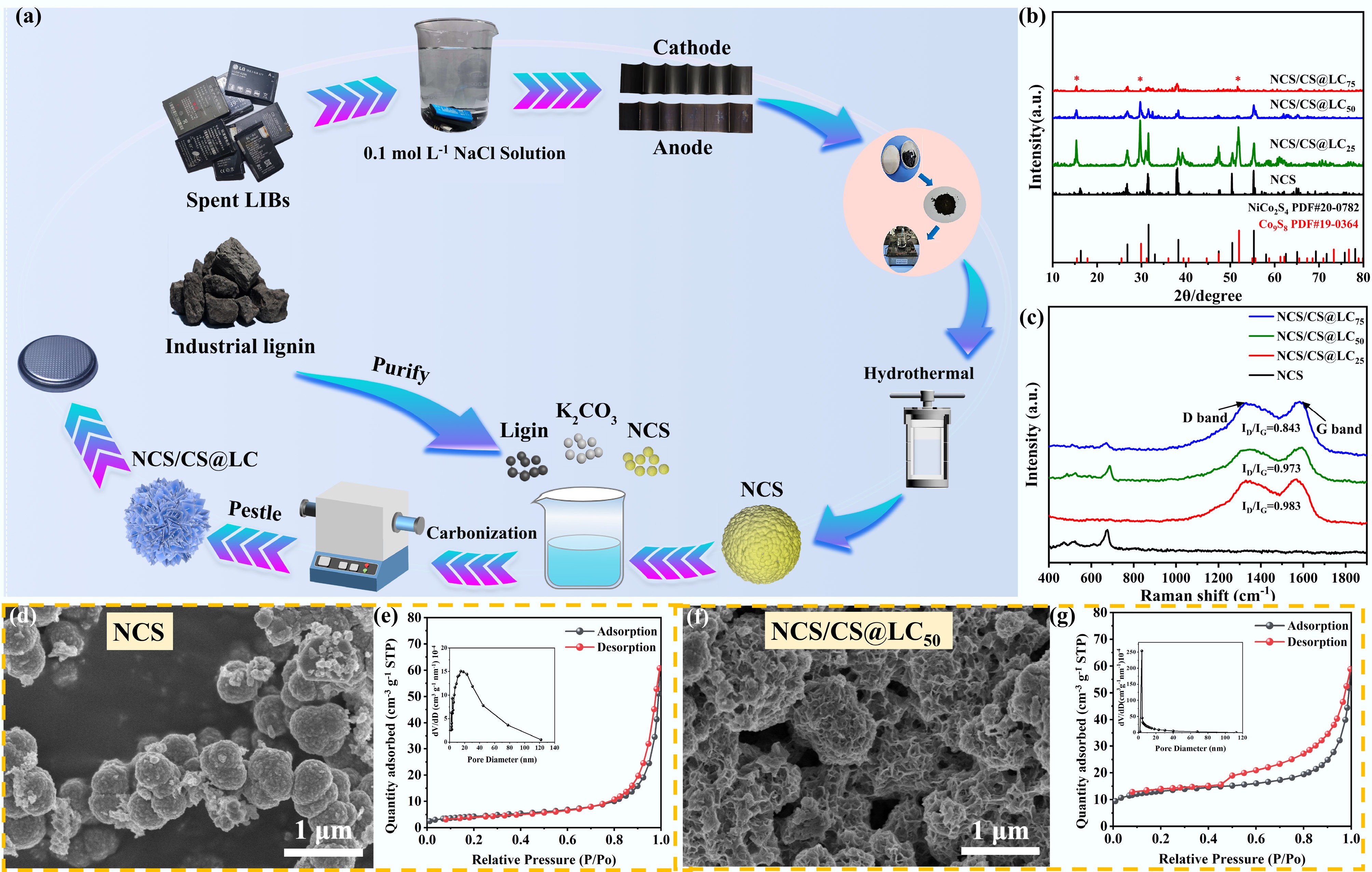
Figure 1.
(a) Schematic of the process for recycling spent mobile phone batteries and industrial lignin into NiCo2S4/Co9S8@LC. (b) XRD patterns of synthesized samples. (c) Raman spectral analysis of synthesized samples. (d) SEM images of NCS. (e) Adsorption-desorption isotherm of NCS. (f) SEM images of NCS/CS@LC50. (g) Adsorption-desorption isotherm of NCS/CS@LC50.
-
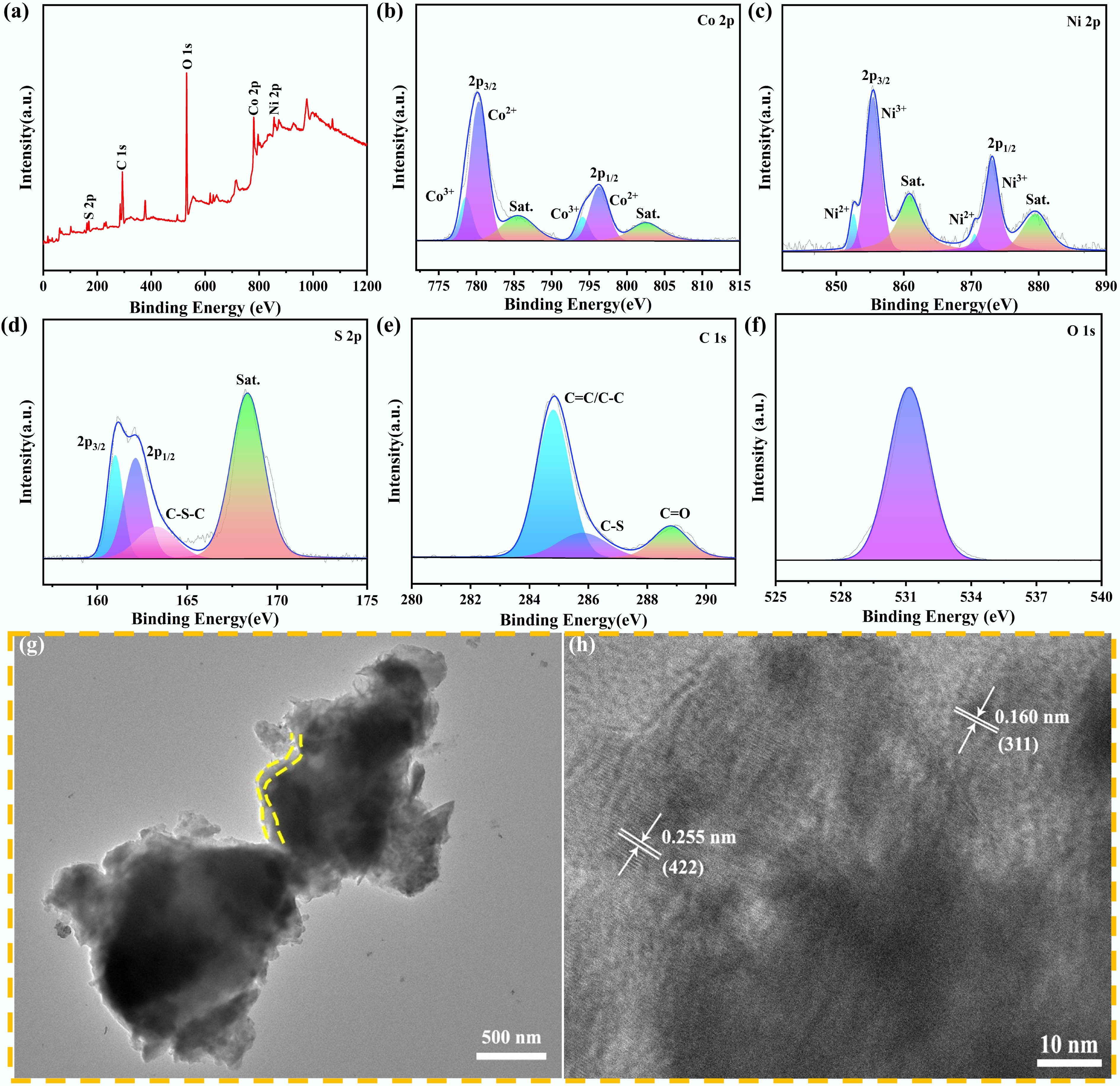
Figure 2.
(a) XPS full spectrum and high-resolution XPS spectra of: (b) Co 2p, (c) Ni 2p, (d) S 2p, (e) C 1s, and (f) O 1s. (g) TEM image of NCS/CS@LC50. (h) Lattice fringes of NCS/CS@LC50.
-
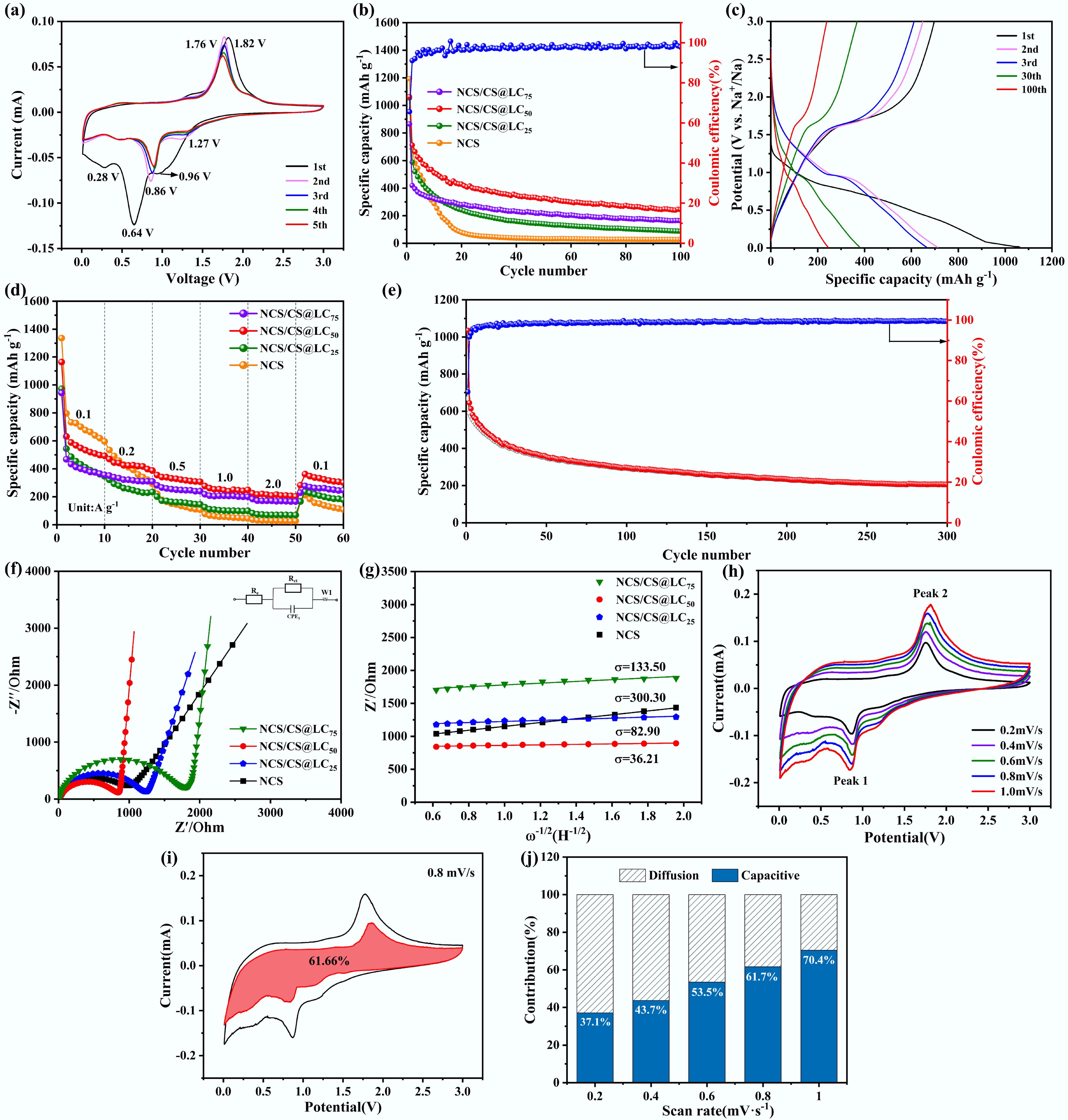
Figure 3.
(a) CV plot of first five cycles for NCS/CS@LC50. (b) Constant current charge-discharge profile of NCS/CS@LC50 at a current of 0.1 A g−1. (c) Capacity-voltage curve of NCS/CS@LC50 for 1st, 2nd, 3rd, 30th, and 100th. (d) Rate performance plot of NCS/CS@LC50 at various current densities (0.1, 0.2, 0.5, 1.0, 2.0, and 0.1 A g−1). (e) Cycling performance of NCS/CS@LC50 at a current density of 0.5 A g−1. (f) Nyquist diagram of synthesized NCS and NCS/CS@LC, accompanied by an equivalent circuit diagram as its illustration. (g) Straight line fitted between Z' and ω−1/2 at low frequencies for synthesized NCS and NCS/CS@LC. (h) CV measurements of NCS/CS@LC50 electrode conducted at varying scan rates. (i) Pseudocapacitive contribution of NCS/CS@LC50 electrode evaluated at a scan rate of 0.8 mV s−1. (j) Ratio of pseudocapacitance control to diffusion control for NCS/CS@LC50 electrode at varying sweep rates.
-
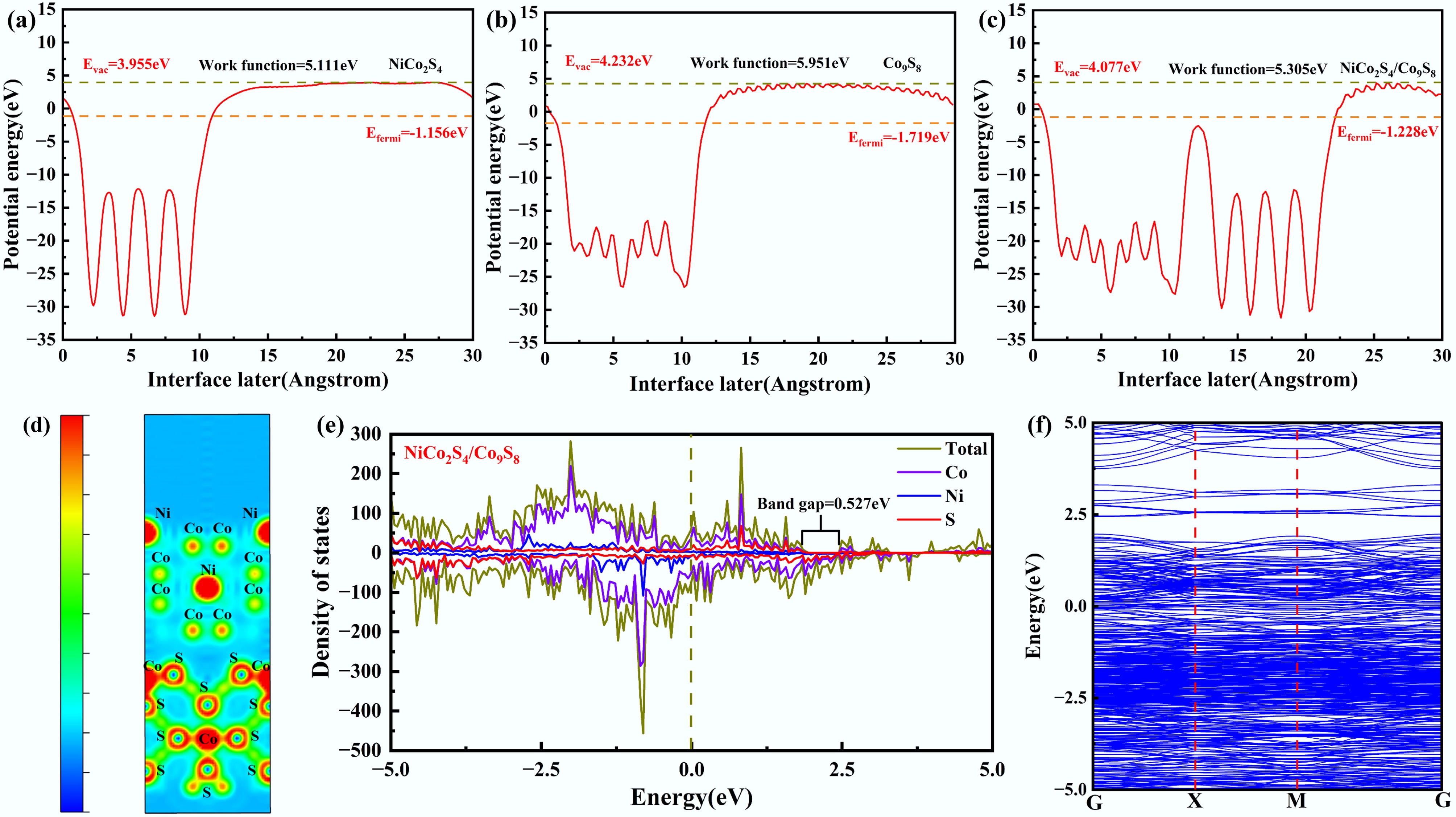
Figure 4.
Calculated work function of (a) NiCo2S4, (b) Co9S8, and (c) NiCo2S4/Co9S8. (d) Charge density difference for the interface of NiCo2S4/Co9S8. (e) Density of state, and (f) band structure for NiCo2S4/Co9S8.
-
Sample Specific surface area
(cm2 g−1)Pore size (nm) Warburg impedance
factor (σ)Na+ diffusion coefficient
D (cm2 s−1)ICE (%) NCS 15.11 23.68 300.30 3.9 × 10⁻¹² 53.15 NCS/CS@LC25 6.03 23.54 82.90 5.1 × 10⁻¹¹ 54 NCS/CS@LC50 42.25 12.98 36.21 2.7 × 10⁻¹⁰ 65.61 NCS/CS@LC75 95.20 10.02 133.50 2.0 × 10⁻¹¹ 46.77 Table 1.
The specific surface area, pore size, Warburg impedance factor (σ) and Na+ diffusion coefficient of the as-synthesized samples
-
Table 2.
Comparison of the electrochemical performance of the synthesized NCS/CS@LC50 in this study with that of NiCo2S4 reported in the literature
Figures
(4)
Tables
(2)