-
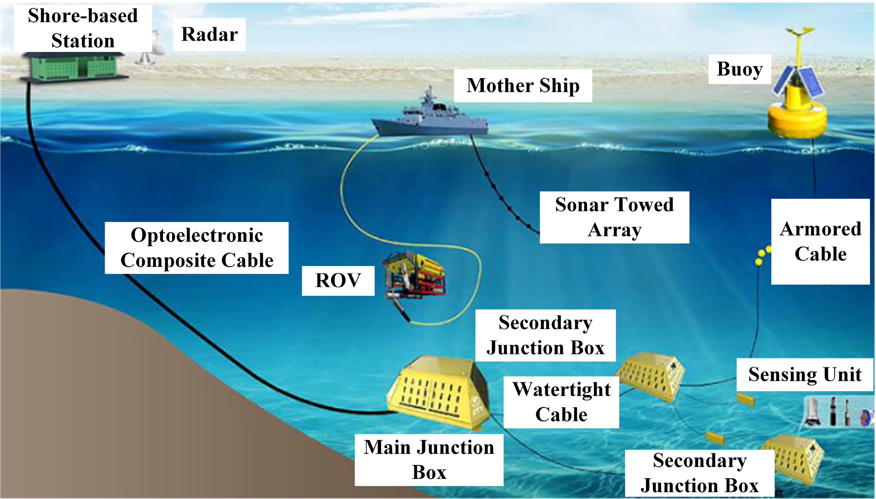
Figure 1.
Submarine observation network.
-
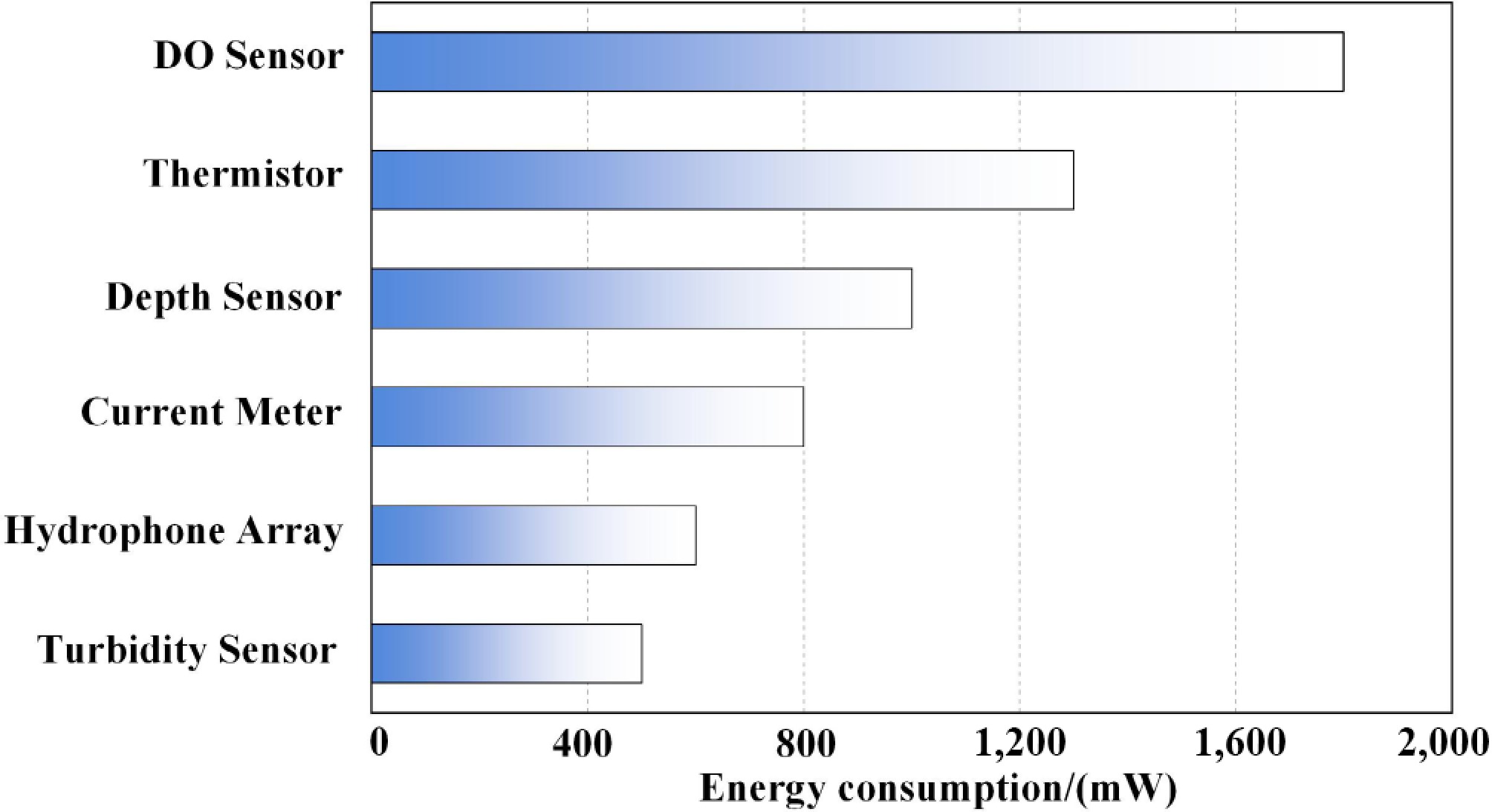
Figure 2.
Energy consumption diagram of underwater devices.
-
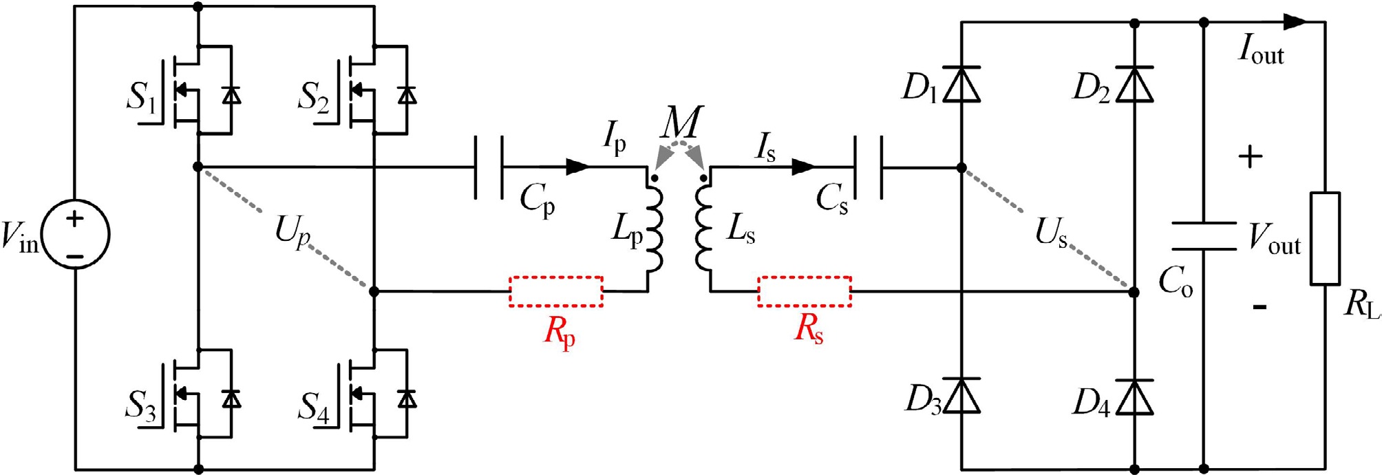
Figure 3.
Schematic diagram of the proposed UWPT system.
-
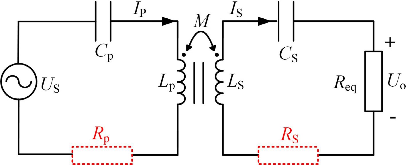
Figure 4.
S-S resonant compensation network.
-
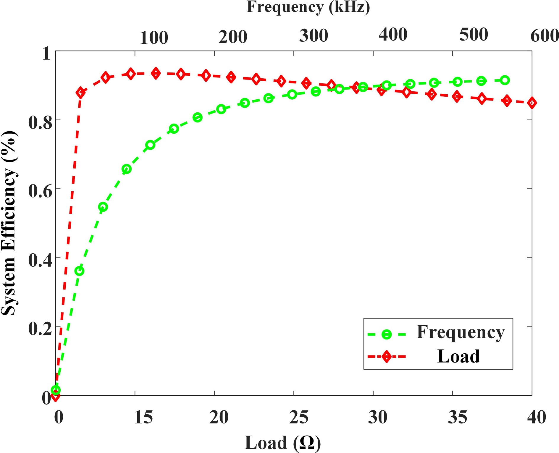
Figure 5.
Efficiency curves as functions of load and frequency variations.
-
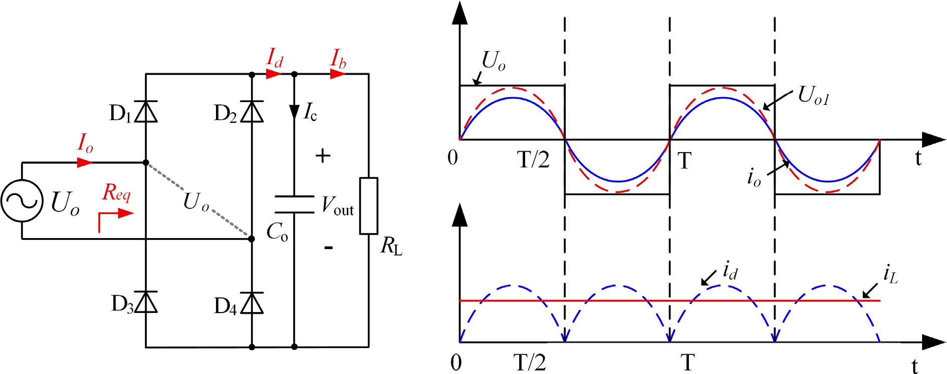
Figure 6.
Rectifier circuit and operation waveforms.
-
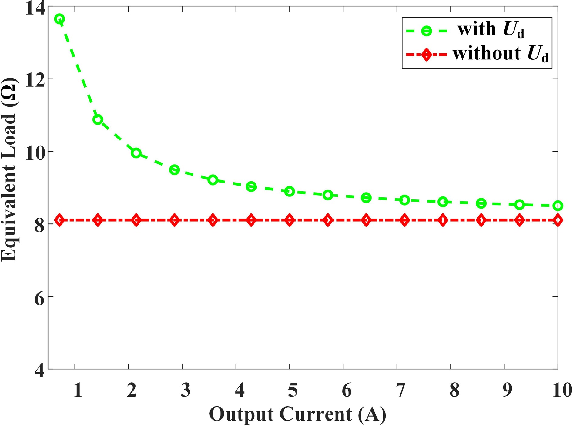
Figure 7.
Relationship between equivalent impedance Req and output current Io.
-
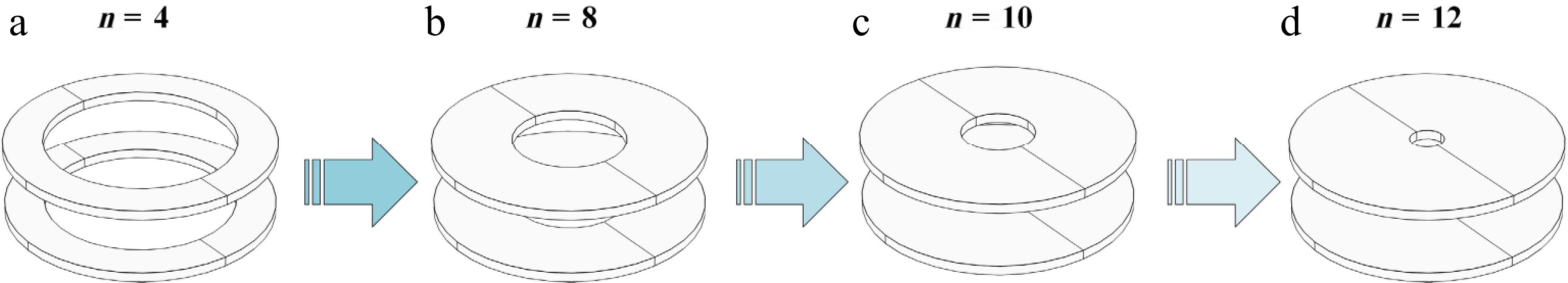
Figure 8.
Relationship between coupling mechanisms and variations in turn number.
-
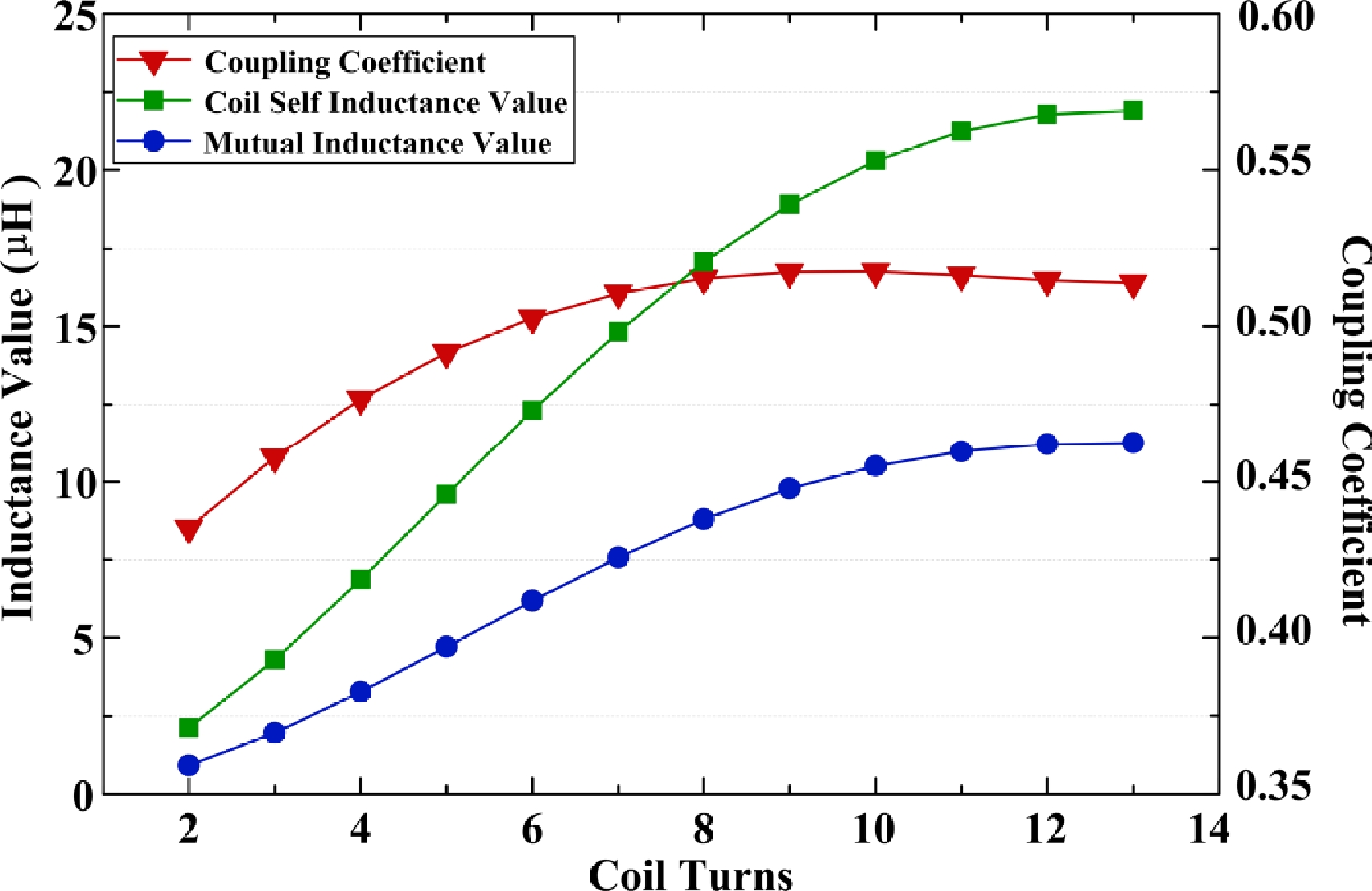
Figure 9.
The relationship between system self-inductance, mutual inductance, coupling coefficient, and number of turns.
-
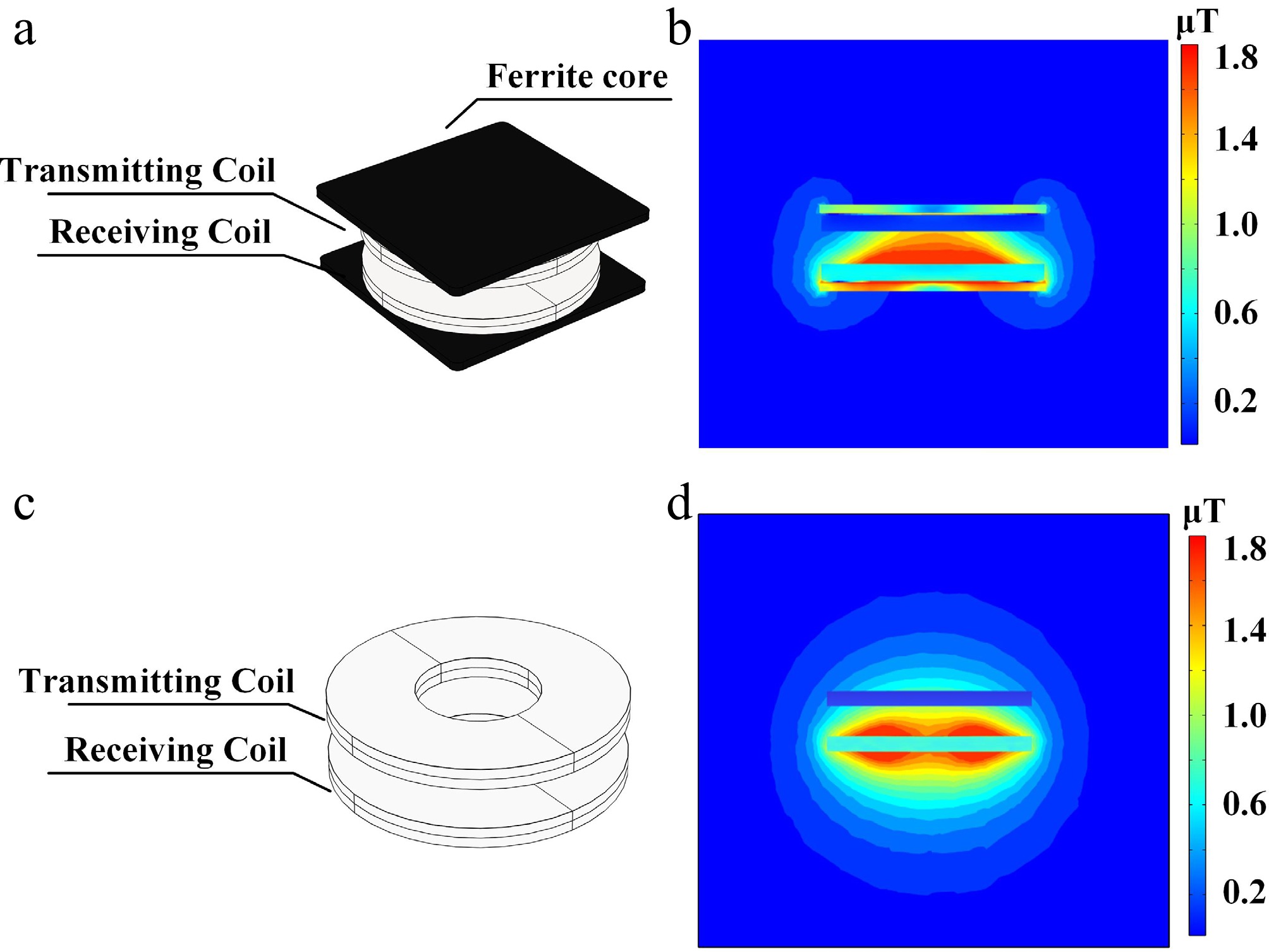
Figure 10.
Influence of ferrite core on magnetic flux density distribution. (a) Coupling mechanism with ferrite layer. (b) Magnetic flux density diagram with ferrite layer coupling mechanism. (c) Coupling mechanism without ferrite layer. (d) Magnetic flux density diagram without ferrite layer coupling mechanism.
-
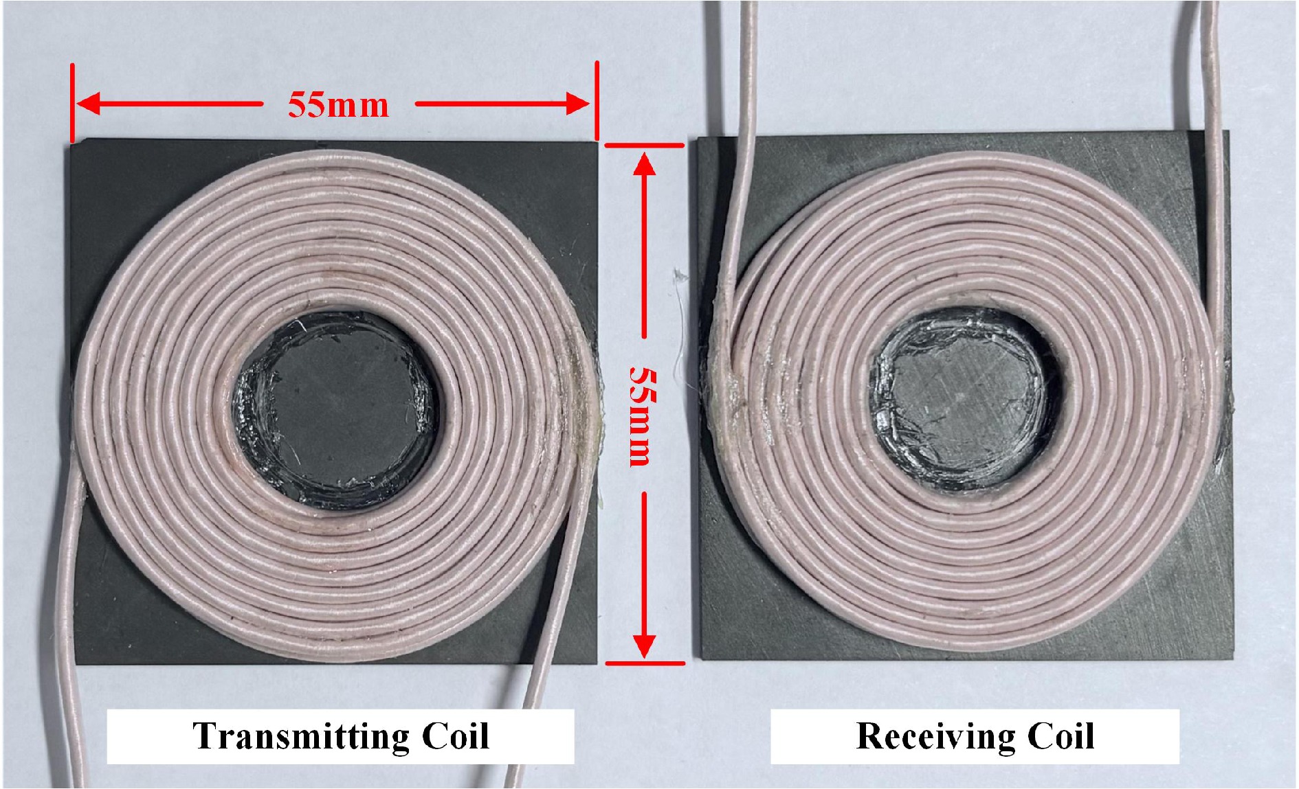
Figure 11.
Physical design of the coupling mechanism.
-
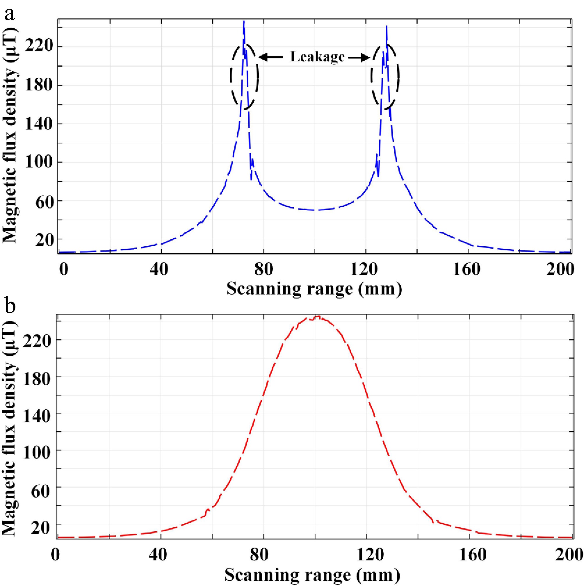
Figure 12.
The curve of magnetic induction intensity variation. (a) With ferrite core. (b) Without ferrite core
-
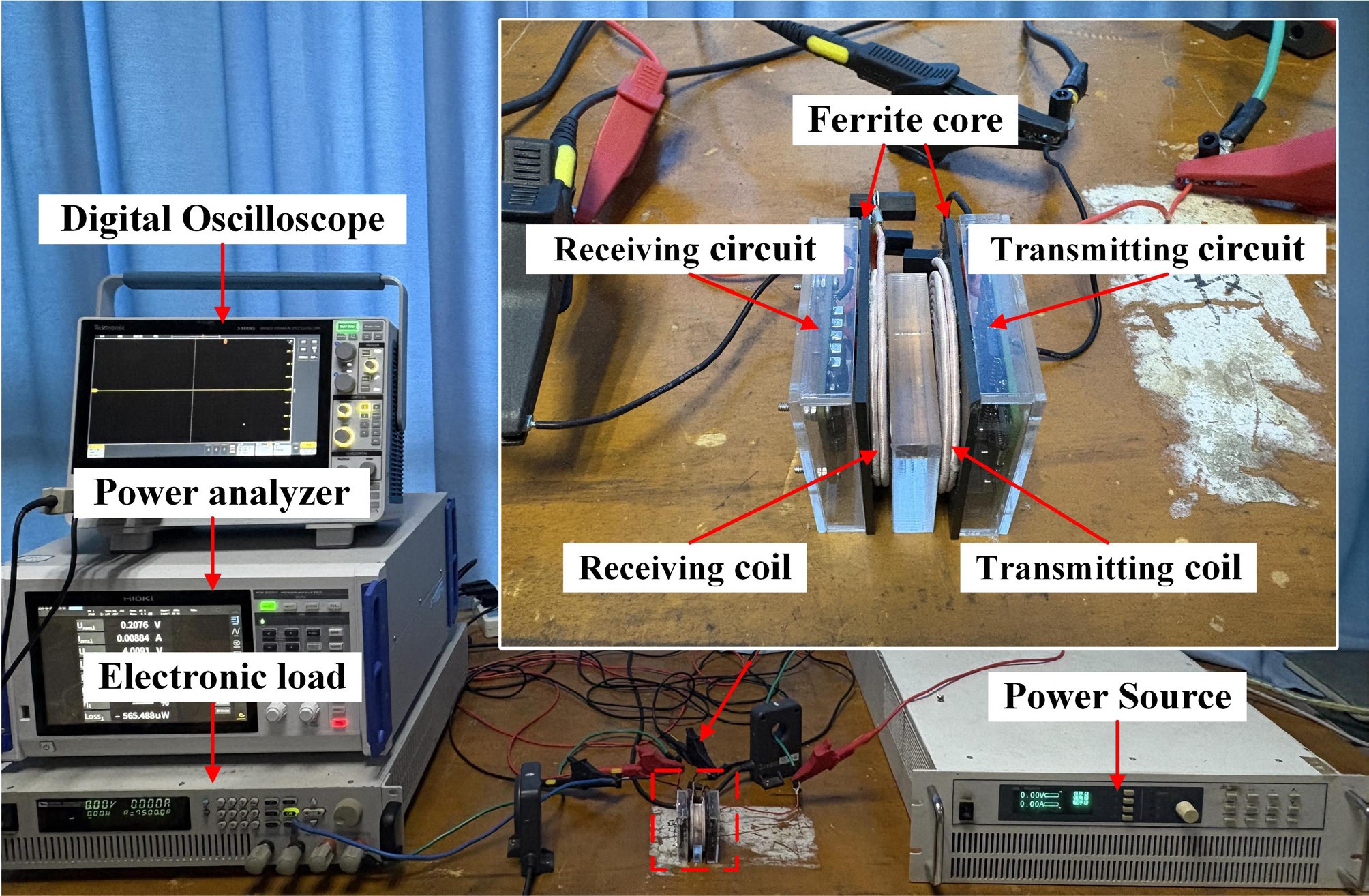
Figure 13.
Experimental setup in air.
-
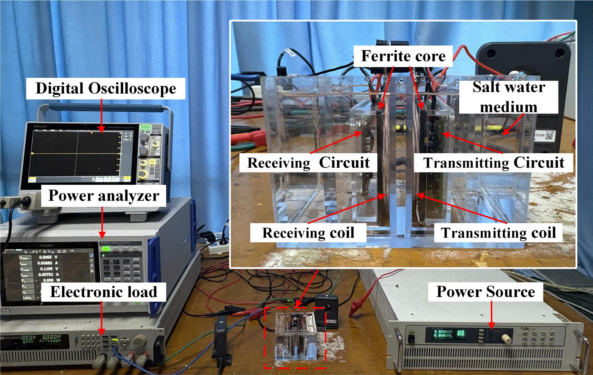
Figure 14.
Experimental setup in salt water.
-
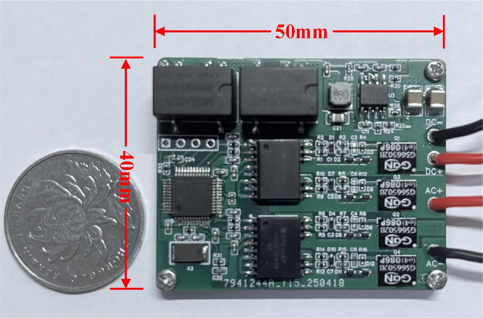
Figure 15.
Physical design of a high-power-density integrated high-frequency inverter.
-
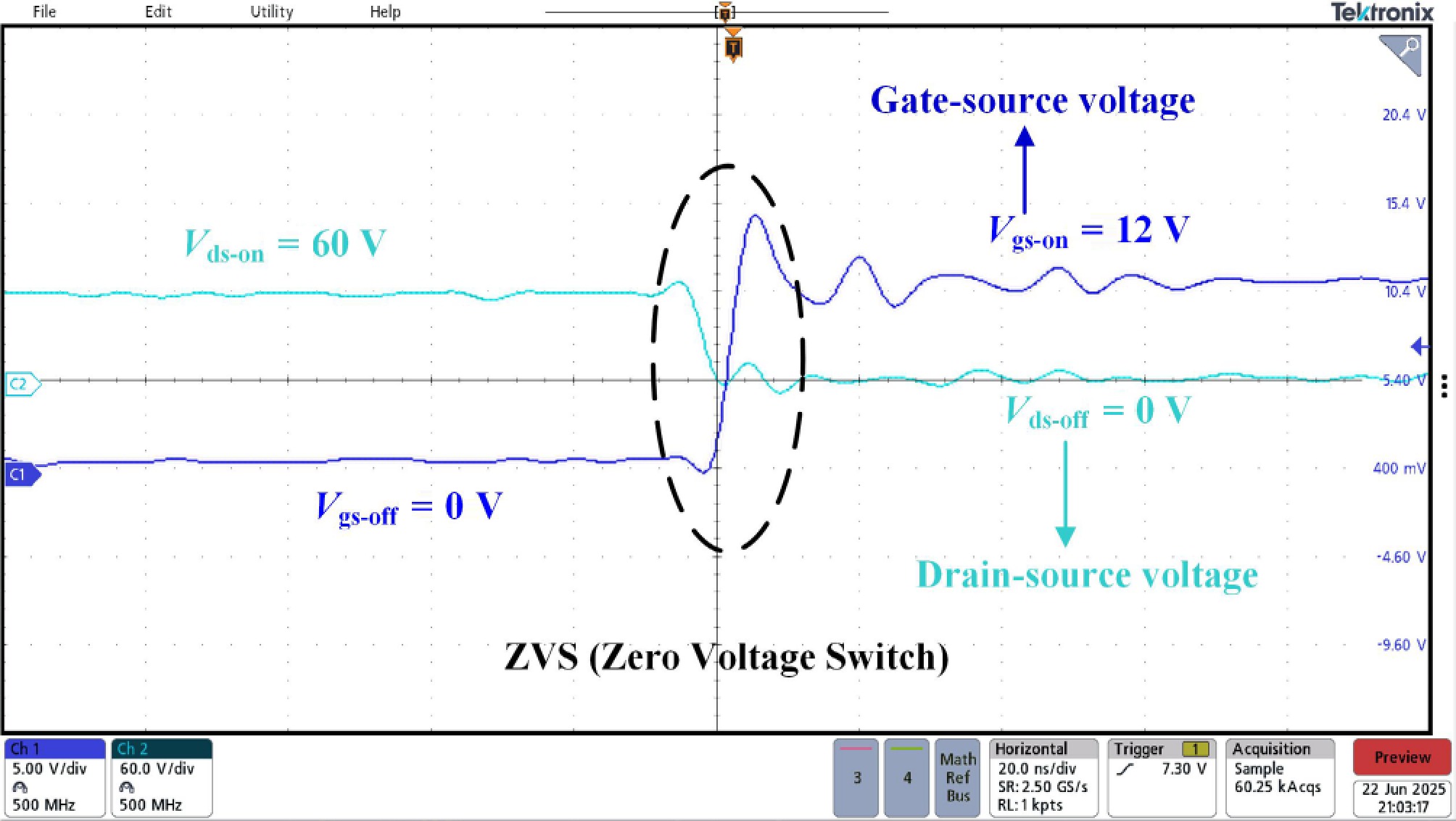
Figure 16.
The driving voltage and drain-source voltage waveforms of the transistor.
-
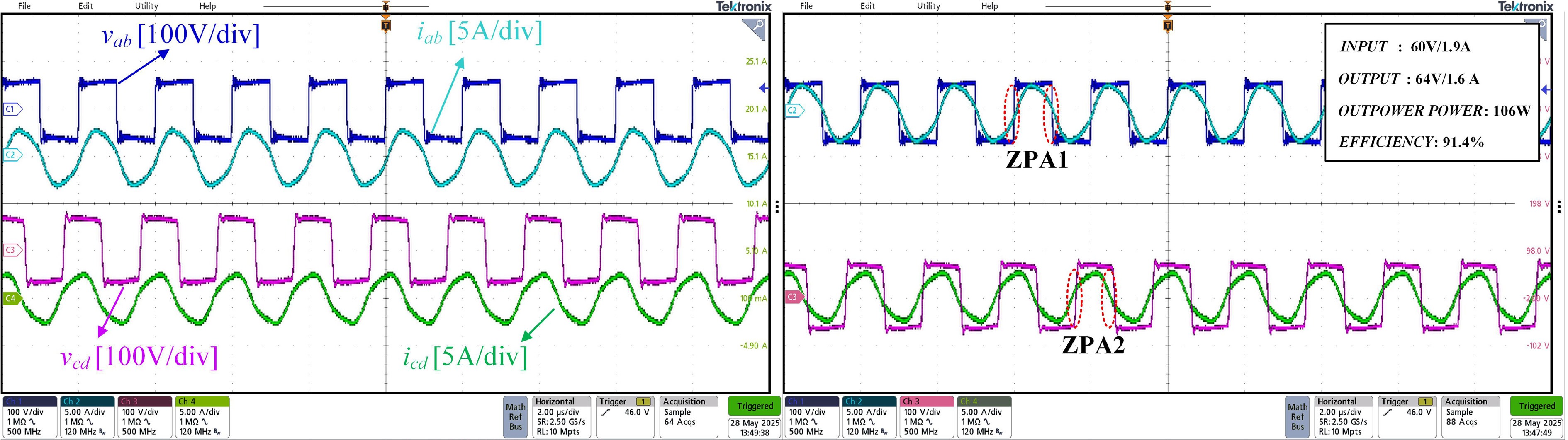
Figure 17.
The voltages and currents on the transmitting and receiving sides of the system.
-
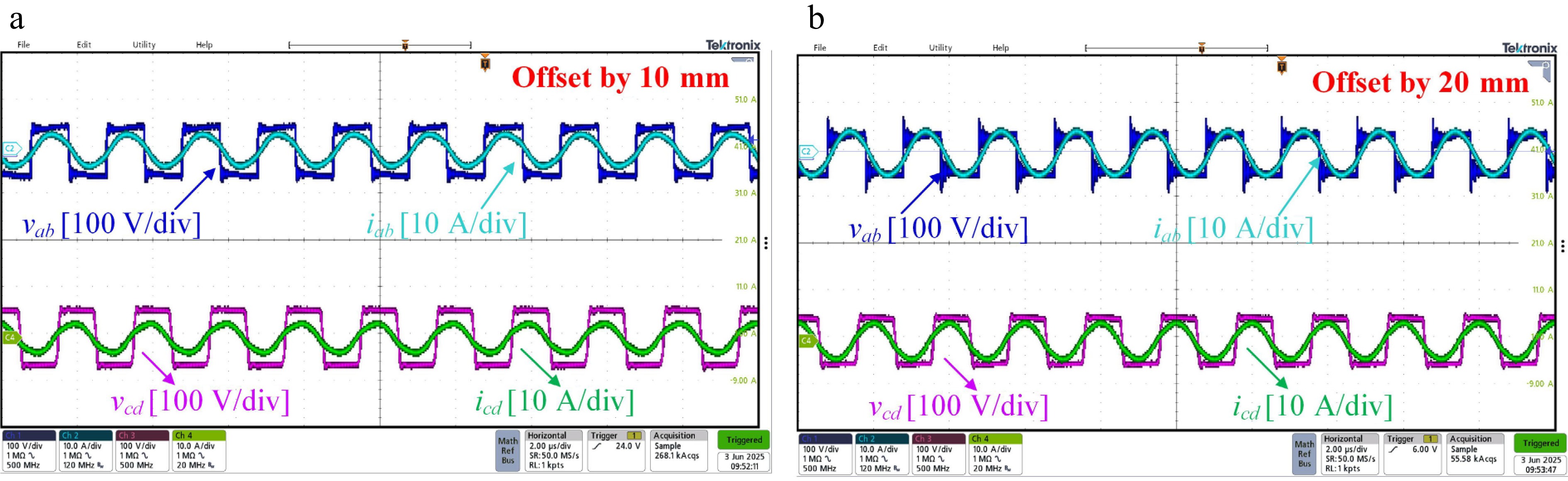
Figure 18.
Voltage and current on the transmitting and receiving sides when the relative position between coils changes. (a) Relative position of the coils is offset by 10 mm. (b) Relative position of the coils is offset by 20 mm.
-
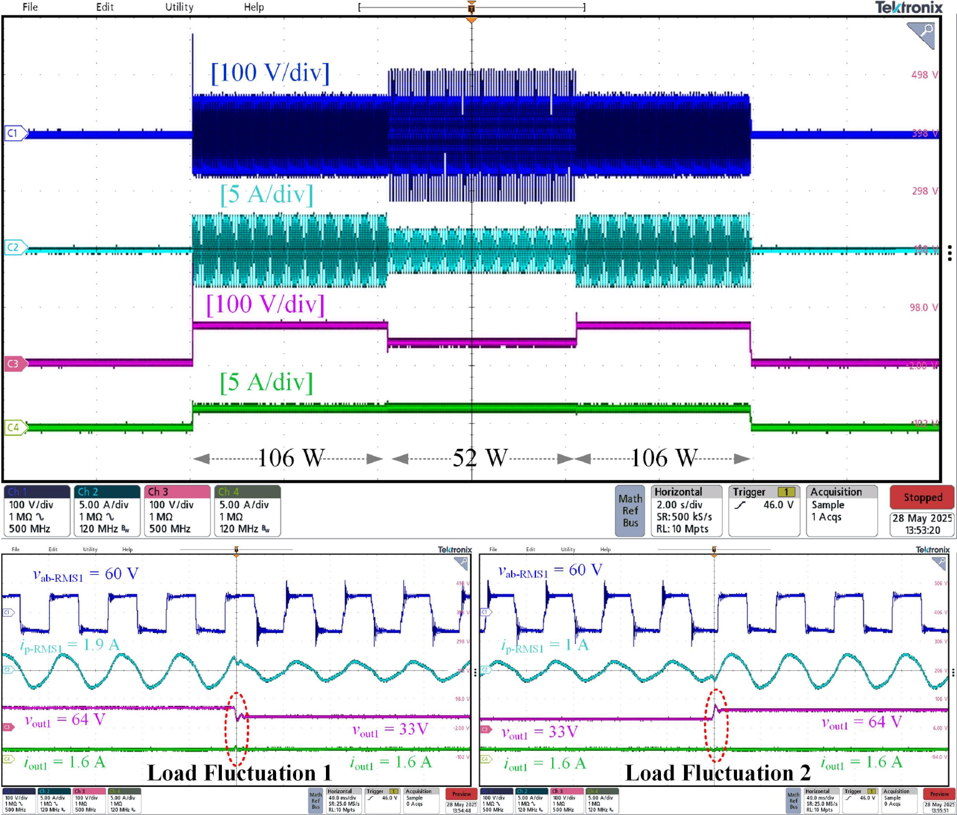
Figure 19.
Output voltage and current in constant current operation (load fluctuation).
-
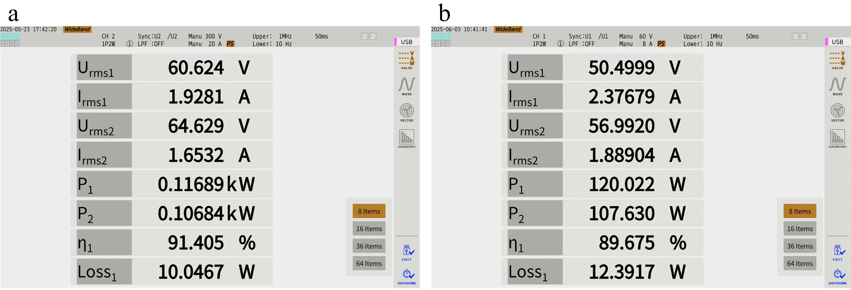
Figure 20.
(a) System operation efficiency (air). (b) System operation efficiency (salt water).
-
Parameters Value Magnetic permeability 3,500 μ0 Transmitting coil 100 × 100 × 10 mm k 0.35 Material PC 95 (MnZn) Receiving coil 100 × 100 × 10 mm d 10 mm d is the transmission distance, k is the coupling coefficient. Table 1.
Parameters of ferrite.
-
Parameters Value Parameters Value Vin 60 V Pout 100 W f 500 kHz Cp 5.06 nF LP 20 μH CS 5.5 nF LS 18 μH RL 39 Ω Table 2.
Parameters of the circuit.
-
Reference Ferrite core Feature Coils size (mm) Power (W) PD (W/cm2) Efficiency An underwater inductive power transfer system with a compact receiver and reduced eddy current loss[24]. Yes CV Tx: 200 × 200;
Rx: 200 × 200300 0.375 88.6% (water) Design and verification of adaptive CC/CV mode switching wireless power transfer system for UAVs based on high switching frequency single-switch LC inverter[25]. No CV&CC Tx: 350 × 350;
Rx: 250 × 250100 0.05 91.6% (air) Undersea simultaneous wireless power and data transfer system with extended communication distance and high rate[26]. Yes CV Tx: 150 × 150;
Rx: 150 × 150500 1.11 90% (water) A dual-output AC–AC converter for double transmitter wireless power transfer systems[27]. Yes CC&AM Tx: 300 × 300 (2s);
Rx: 280 × 280384 0.22 93.7% (air) This work Yes CC&AM Tx: R = 27.5;
Rx: R = 27.5100 2.1 91.4% (air);
89.6% (seawater)Notes: R is the diameter of a circle, h is the height of the cylinder, CC is the constant current feature, CV is the constant voltage feature, AM is the anti-migration feature, 2s indicates that two groups of coils, PD indicates Power Density. Table 3.
Comparison with state-of-art works.
Figures
(20)
Tables
(3)