


-
The submarine observation network can be called the third observation platform of the earth (Fig. 1). This network includes pressure gauges, seismic geophones, temperature sensors, chlorophyll sensors, carbon dioxide sensors, depth gauges, salinometers, turbidimeters, gravimeters, current meters, underwater cameras, Autonomous Underwater Vehicles (AUVs), etc. Different sensors or devices are integrated into a single node and scaled up to achieve regional observation objectives[1,2]. The establishment of a submarine information observation network is the current development need for marine science, marine ecological research, national security analysis, and natural disaster prevention[3−6].
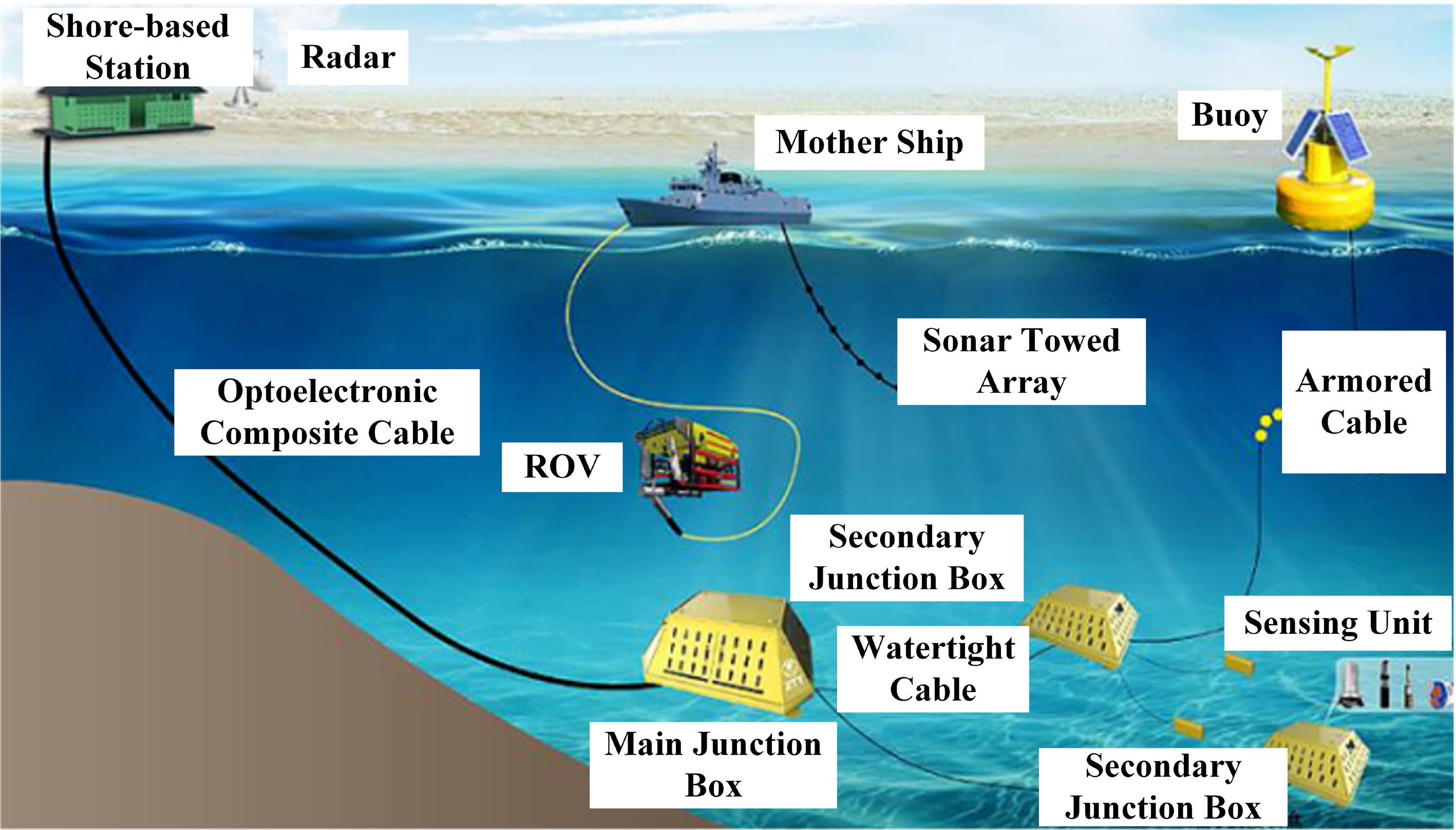
Figure 1.
Submarine observation network.
A reliable and stable long-term power supply is however essential for autonomous underwater vehicles and underwater intelligent sensors to maintain optimal performance and operational stability. Figure 2 presents the power consumption of several typical underwater intelligent sensors[7,8].
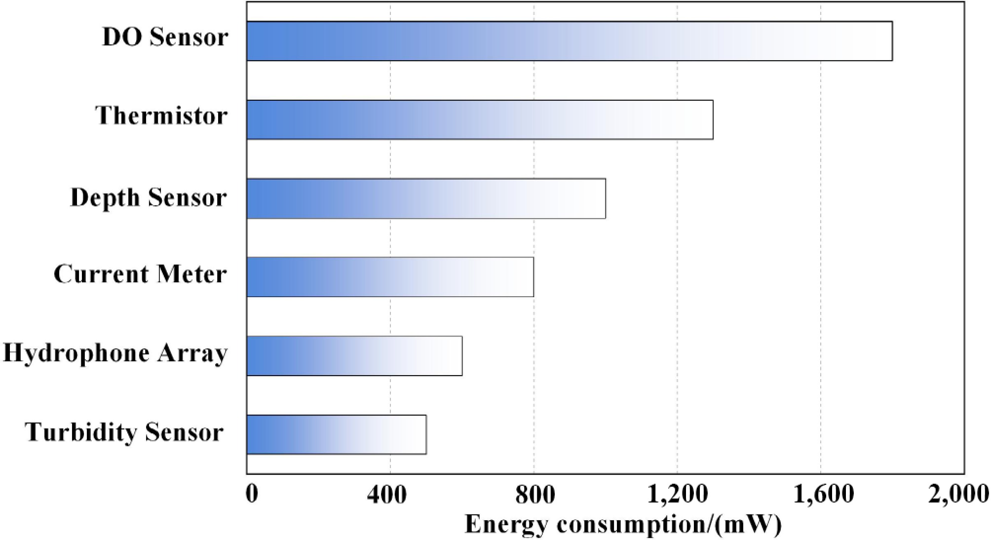
Figure 2.
Energy consumption diagram of underwater devices.
These underwater intelligent sensors are typically deployed at depths of up to 300 m, with a maximum operational depth reaching 6000 m. Most of them consume less than 10 W of power. For long-term deployments, battery-powered systems face significant challenges, including high costs and inefficiency due to the need for equipment retrieval, as well as potential environmental contamination from electrolyte leakage. Alternatively, cable-connected systems impose physical limitations on sensor placement flexibility and are susceptible to biofouling and ocean current disturbance[9].
To ensure the stable and reliable operation of autonomous underwater vehicles (AUVs) and underwater intelligent sensors, this study investigates and designs an undersea wireless power transfer (UWPT) system. This system employs underwater mobile devices as UWPT transmitting terminals to provide contactless power delivery to sensors deployed within the submarine observation network. This approach reduces both the required battery size and capacity for the equipment, while eliminating issues related to cable wear and addressing sealing challenges associated with underwater sensor deployment[10,11].
Currently, research and applications of undersea wireless power transfer systems primarily focus on two methodologies: the undersea magnetic coupling resonant WPT method, which employs high-frequency alternating magnetic fields[12], and the undersea electric field-based WPT method, which utilizes high-frequency alternating electric fields[13]. Among these, magnetic coupling resonance has become the more mainstream UWPT approach due to its high-power transmission efficiency and stable system performance. However, undersea magnetic coupling resonant WPT systems face several challenges. For instance, eddy current losses are induced by the high electrical conductivity of seawater, and variations in the coupling coefficient occur due to relative coil displacement caused by ocean currents. These factors significantly degrade system transmission performance[14,15]. In research on magnetic coupling coils, an offline parameter identification method has been proposed[16]. By comparing the model's calculated values with measured data from an impedance analyzer, the equivalent impedance of the coil in seawater can be effectively identified. Another study systematically compared the core loss, winding loss, and eddy current loss in three media: air, fresh water, and seawater[17]. It analyzed the variation patterns of these losses, identified the key factors affecting them under different media and operating conditions, and quantified their specific proportions. Additionally, in response to the application requirements of underwater vehicles, a magnetically coupled wireless power transfer system, with a dual-transmitter coil structure was developed[18]. This design reduces eddy current loss by decreasing the current required in the transmitter coil. Experimental verification shows that this structure can reduce the eddy current loss caused by the transmitter coil to less than half of that in traditional coils.
To maximize the transmission efficiency of wireless power transfer systems, researchers have developed various optimization control strategies. These include modulating the pulse width of the active rectifier and the duty cycle of the DC/DC converter to maintain optimal load matching. Furthermore, closed-loop control strategies, such as PI control, robust control, and linear active disturbance rejection control (LADRC), have been employed to enhance the system's dynamic response and output stability. In terms of system modeling, a discrete-time iterative model for an LCC-S type WPT system was established to describe its dynamic behavior[19]. The analysis demonstrated that, with fixed controller parameters, the system's stability margin decreases with variations in load and mutual inductance, thereby compromising operational reliability. Further research led to the development of a large-signal continuous model based on the LCC-S compensation network, which achieves a unified and accurate characterization of both the steady-state and dynamic performance of the system[20].
However, most of the aforementioned studies consider only the optimal load of the compensation network during impedance matching, while neglecting the impact of rectifier losses on the system's optimal load. As a result, discrepancies arise between the theoretical model and the measured efficiency characteristics.
Considering the critical power supply requirements of underwater intelligent sensors for marine exploration, this paper, with a practical value orientation, presents a highly integrated UWPT system featuring high power density. On the one hand, the high-frequency inverter employs (ZVS) technology, which not only reduces switching losses but also adaptively compensates for frequency deviations caused by the seawater medium through an inductive-biased circuit design. An integrated structural design suppresses magnetic field leakage interference with sensor data acquisition. On the other hand, a compensation-topology-based equivalent model for the nonlinear rectifier bridge load is established to quantify the impact of rectifier diode voltage drops on load matching, thereby reducing calculation errors for the optimal load. Combined with a ferrite core, the system enhances the coupling coefficient to 0.45 and suppresses 90% of magnetic flux leakage.
-
The circuit topology of the proposed UWPT system in this paper is illustrated in Fig. 3, which is primarily composed of five components: a high-frequency inverter network, a primary compensation network, a coupling mechanism, a secondary compensation network, and a rectification filtering network. Here, Vin represents the DC power supply, and four switching tubes (S1–S4) form a full-bridge high-frequency inverter. CP is the transmitting compensation capacitor, while LP and LS are the transmitting coil and receiving coil, respectively. CS serves as the receiving compensation capacitor, and (D1–D4) constitute the rectifier bridge. Co acts as the filter capacitor.
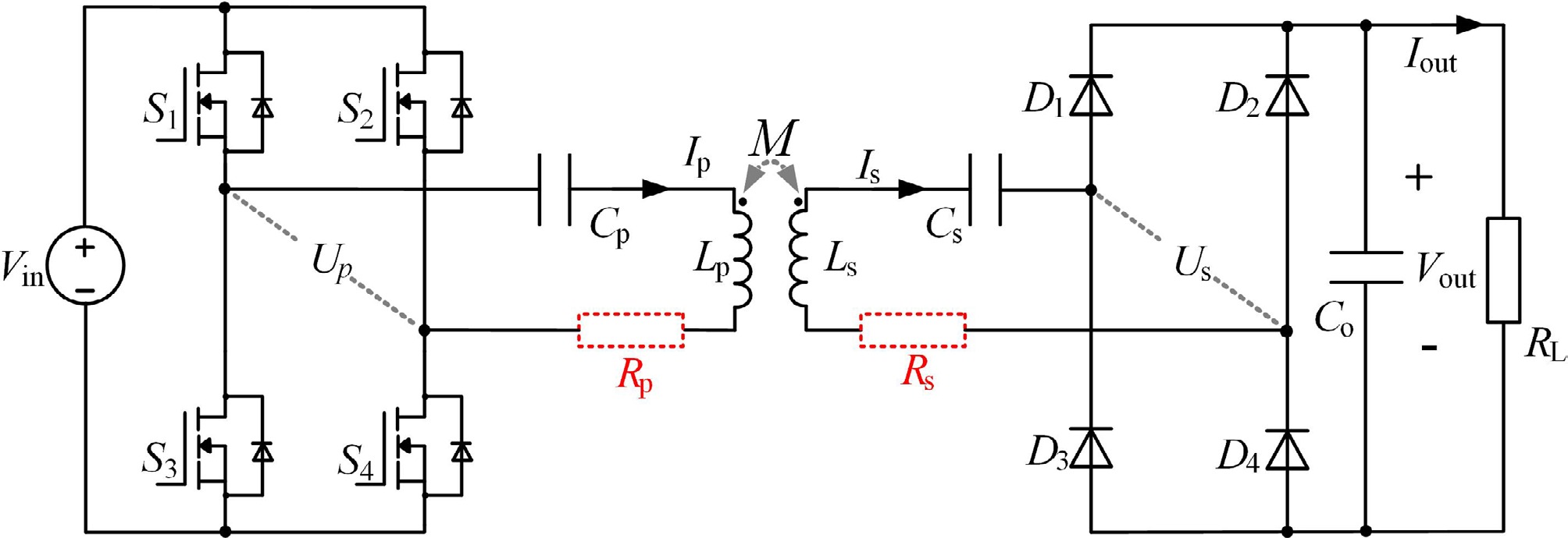
Figure 3.
Schematic diagram of the proposed UWPT system.
The compensation network is designed to achieve circuit resonance, making the current and voltage in phase. This eliminates reactive power during power transmission and enables efficient wireless power transfer[21,22]. The tuning method of the S-S compensation network is unaffected by mutual inductance fluctuations, maintaining stable transmission characteristics even when coil misalignment occurs due to ocean current surges. Figure 4 shows the resistive components in the equivalent circuit model of the S-S resonant compensation network. RP and RS are the parasitic resistances of the transmitting coil and receiving coil, respectively, and Req is the equivalent resistance of the load and rectifier circuit.
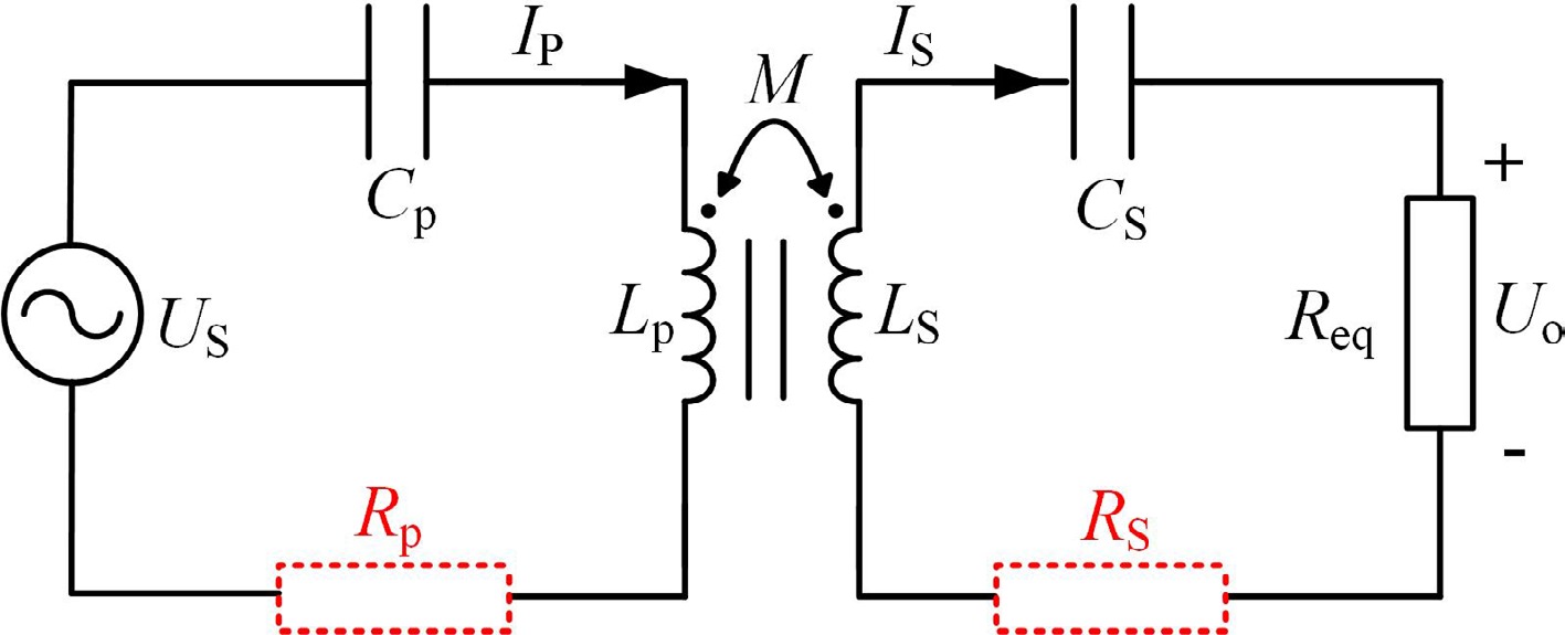
Figure 4.
S-S resonant compensation network.
Analysis of circuit output characteristics
-
To simplify the analysis, this paper ignores the high-order harmonic components. The effective value of US can be expressed as:
$ {U}_{\text{S}}=\dfrac{2\sqrt{2}}{\text π}{U}_{\text{in}} $ (1) The relevant circuit parameters in Fig. 4 can be expressed as:
$\left\{\begin{aligned}& {X}_{\text{P}}=j\omega {L}_{\text{P}}-j\dfrac{1}{\omega {C}_{\text{P}}}\\& {X}_{\text{S}}=j\omega {L}_{\text{S}}-j\dfrac{1}{\omega {C}_{\text{S}}} \end{aligned}\right. $ (2) Based on Kirchhoff's voltage law, the KVL equation can be written as:
$ \left[\begin{matrix}{U}_{\text{S}}\\ 0\\ \end{matrix}\right]=\left[\begin{matrix}{Z}_{\text{P}} & -j\omega M\\ -j\omega M & {Z}_{\text{S}}\\ \end{matrix}\right]\left[\begin{matrix}{I}_{\text{P}}\\ {I}_{\text{S}}\\ \end{matrix}\right] $ (3) where, ω is angular frequency, ZP is impedance at the transmitting end, ZS is impedance at the receiving end, and M is the mutual inductance coefficient of the coupling mechanism.
ZP and ZS can be respectively expressed as:
$ \begin{cases} {Z}_{\text{P}}={R}_{\text{P}}+{X}_{\text{P}}\\ {Z}_{\text{S}}={R}_{\text{S}}+{R}_{\text{eq}}+{X}_{\text{S}}\\ \end{cases} $ (4) According to Eq. (2), the current in the UWPT circuit is:
$ \begin{cases} {I}_{\text{P}}=\dfrac{({X}_{\text{S}}+{R}_{\text{S}}+{R}_{\text{eq}}){U}_{\text{S}}}{[({X}_{\text{P}}+{R}_{\text{P}})({X}_{\textit{S}}+{R}_{\text{S}}+{R}_{\text{eq}})+{\omega }^{2}{M}^{2}]}\\ {I}_{\text{S}}=\dfrac{j\omega M{U}_{\mathrm{S}}}{[({X}_{\text{P}}+{R}_{\text{P}})({X}_{\text{S}}+{R}_{\text{S}}+{R}_{\text{eq}})+{\omega }^{2}{M}^{2}]}\\ \end{cases} $ (5) The following resonant condition should be satisfied:
$ \omega =\dfrac{1}{\sqrt{{L}_{\text{S}}{C}_{\text{S}}}}=\dfrac{1}{\sqrt{{L}_{\text{P}}{C}_{\text{P}}}} $ (6) Substituting Eq. (6) into Eq. (3), the expression for Eq. (7) can be rewritten as follows:
$ \begin{cases} {I}_{\text{P}}=\dfrac{({R}_{\text{S}}+{R}_{\text{eq}}){U}_{\text{S}}}{{R}_{\text{P}}\text{}({R}_{\text{S}}+{R}_{\text{eq}})+{\omega }^{2}{M}^{2}}\\ {I}_{\text{S}}=\dfrac{j\omega M{U}_{\text{S}}}{{R}_{\text{P}}\text{}({R}_{\text{S}}+{R}_{\text{eq}})+{\omega }^{2}{M}^{2}}\\ \end{cases} $ (7) According to the resonant condition, the expression for the input impedance Zin of the presented UWPT system is:
$ {Z}_{\text{in}}=\dfrac{{U}_{\text{S}}}{{I}_{\text{P}}}=\dfrac{{R}_{\text{P}}\text{}({R}_{\text{S}}+{R}_{\text{eq}})+{\omega }^{2}{M}^{2}}{{R}_{\text{S}}+{R}_{\text{eq}}} $ (8) It can be seen that the input impedance of the system exhibits the operation mode of ZPA.
The expressions for input and output power of the UWPT system are:
$ \begin{cases} {P}_{\text{in}}={I}_{\text{P}}{U}_{\text{S}}=\dfrac{({R}_{\text{S}}+{R}_{\text{eq}})U_{\text{S}}^{2}}{{R}_{\text{P}}\text{}({R}_{\text{S}}+{R}_{\text{eq}})+{\omega }^{2}{M}^{2}}\\ {P}_{\text{out}}=I_{\text{S}}^{2}{R}_{\text{eq}}=\dfrac{{\omega }^{2}{M}^{2}U_{\text{S}}^{2}{R}_{\text{eq}}}{{[{{R}_{\text{P}}}\text{}({{R}_{\text{S}}}+{{R}_{\text{eq}}})+{{\omega }^{2}}{{M}^{2}}]}^{2}}\\ \end{cases} $ (9) The transmission efficiency of the UWPT system is:
$ \eta =\dfrac{{P}_{\text{out}}}{{P}_{\text{in}}}=\dfrac{{\omega }^{2}{M}^{2}{R}_{\text{eq}}}{\left({R}_{\text{S}}+{R}_{\text{L}}\right)\left[{R}_{\text{P}}\left({R}_{\text{S}}+{R}_{\text{eq}}\right)+{\omega }^{2}{M}^{2}\right]} $ (10) By taking the partial derivative of the efficiency with respect to Req, and setting ∂η/∂Req = 0, the optimal load at the maximum efficiency point of the UWPT system can be obtained as:
$ {R}_{\text{opt}}=\sqrt{\dfrac{{\omega }^{2}{M}^{2}{R}_{\text{S}}}{{R}_{\text{P}}}+R_{\text{S}}^{2}} $ (11) As shown in Fig. 5, the efficiency curve of the UWPT system is plotted against load and frequency variations. It can be seen that as the load increases, the synergy of the power transmission process improves, enabling more electrical energy to be effectively delivered to the load end, which in turn enhances the efficiency. However, once the load exceeds a certain critical threshold, problems such as increased internal system losses and impedance mismatch begin to emerge, causing a gradual decline in efficiency. In the early stages of frequency increase, the system benefits from improved resonance characteristics, leading to a rapid rise in efficiency. However, as the frequency continues to rise, frequency-dependent loss mechanisms in the marine environment—such as dielectric and eddy current losses—become more pronounced. These losses progressively counteract the positive effects of increasing frequency on efficiency, resulting in a flattening of the efficiency curve. The optimal efficiency point, influenced by both load and frequency, can be identified using appropriate mathematical tools.
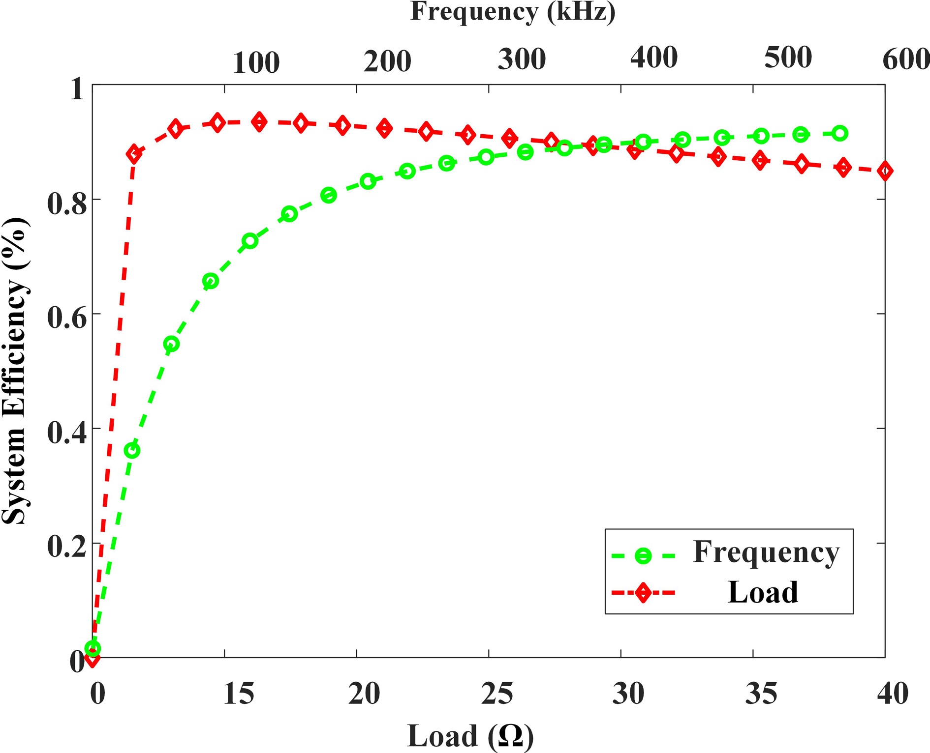
Figure 5.
Efficiency curves as functions of load and frequency variations.
However, neglecting rectifier losses may result in significant discrepancies between theoretical circuit analysis and real-world conditions, leading to inaccuracies in determining the maximum efficiency load point. Moreover, achieving zero-voltage switching (ZVS) for the inverter is particularly challenging within a fully resonant compensation network. This limitation leads to considerable switching losses, which further reduce overall UWPT system efficiency.
Load analysis of a nonlinear rectifier bridge
-
When the rectifier bridge is in the conducting state, the voltage drop across the diodes introduces nonlinearity in the load characteristics, thereby affecting the overall power conversion performance[23]. Figure 6 shows the simplified equivalent circuit along with the corresponding voltage and current waveforms.
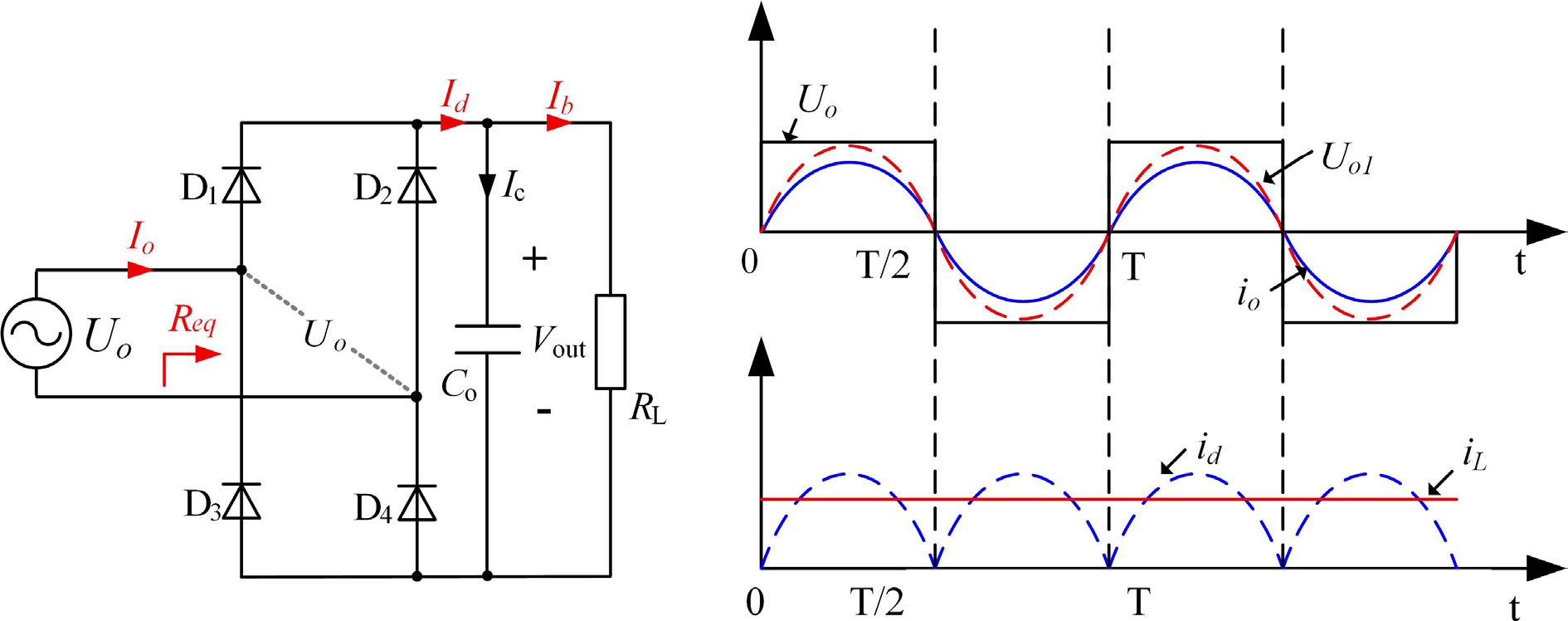
Figure 6.
Rectifier circuit and operation waveforms.
From the perspective of the rectifier bridge input port, both the input voltage and current are periodic in nature. The input current can be approximated as a continuous sine wave, expressed as:
$ {I}_{\text{o}}=\sqrt{2}{I}_{\text{o}}\sin (\omega ,t) $ (12) The current of each branch on the output side of the rectifier bridge can be written as:
$ \begin{cases} {I}_{\text{d}}=\left| {I}_{\text{o}}\right| \approx\sqrt{2}{I}_{\text{o}}\left| \sin (\omega ,t)\right| \\ {I}_{\text{b}}=\dfrac{1}{T}\int_{0}^{T}\left| {I}_{\text{o}}\right| dt=\dfrac{2\sqrt{2}{I}_{\text{o}}}{\text π} \end{cases} $ (13) When the rectifier bridge is conducting, current flows through two diodes, and the fundamental component Uo1 of Uo can be expressed as:
$ {U}_{o1}=\dfrac{4}{\text π}\left(2{U}_{\text{d}}+\dfrac{2\sqrt{2}{I}_{\text{o}}}{\text π}{R}_{\text{L}}\right)\sin (\omega ,t) $ (14) where, Ud is the on-state voltage drop of the rectifier diode.
Assuming only the fundamental component is taken into account, the equivalent impedance at the input port can be expressed as:
$ {R}_{\text{eq}}=\dfrac{{U}_{\mathrm{o}1}}{{I}_{\textit{o}}}=\dfrac{4\sqrt{2}{U}_{\text{d}}}{{\text π} {I}_{\text{o}}}+\dfrac{8}{{\text π}^{2}}{R}_{\text{L}} $ (15) From Eq. (15), it can be seen that the equivalent impedance Req is influenced by RL, Ud, and Io. Since Ud is an inherent parameter of the diode, the variation in Io is the primary factor affecting Req. Figure 7 illustrates the curves of Req as a function of Io under constant load RL, with and without the consideration of Ud.
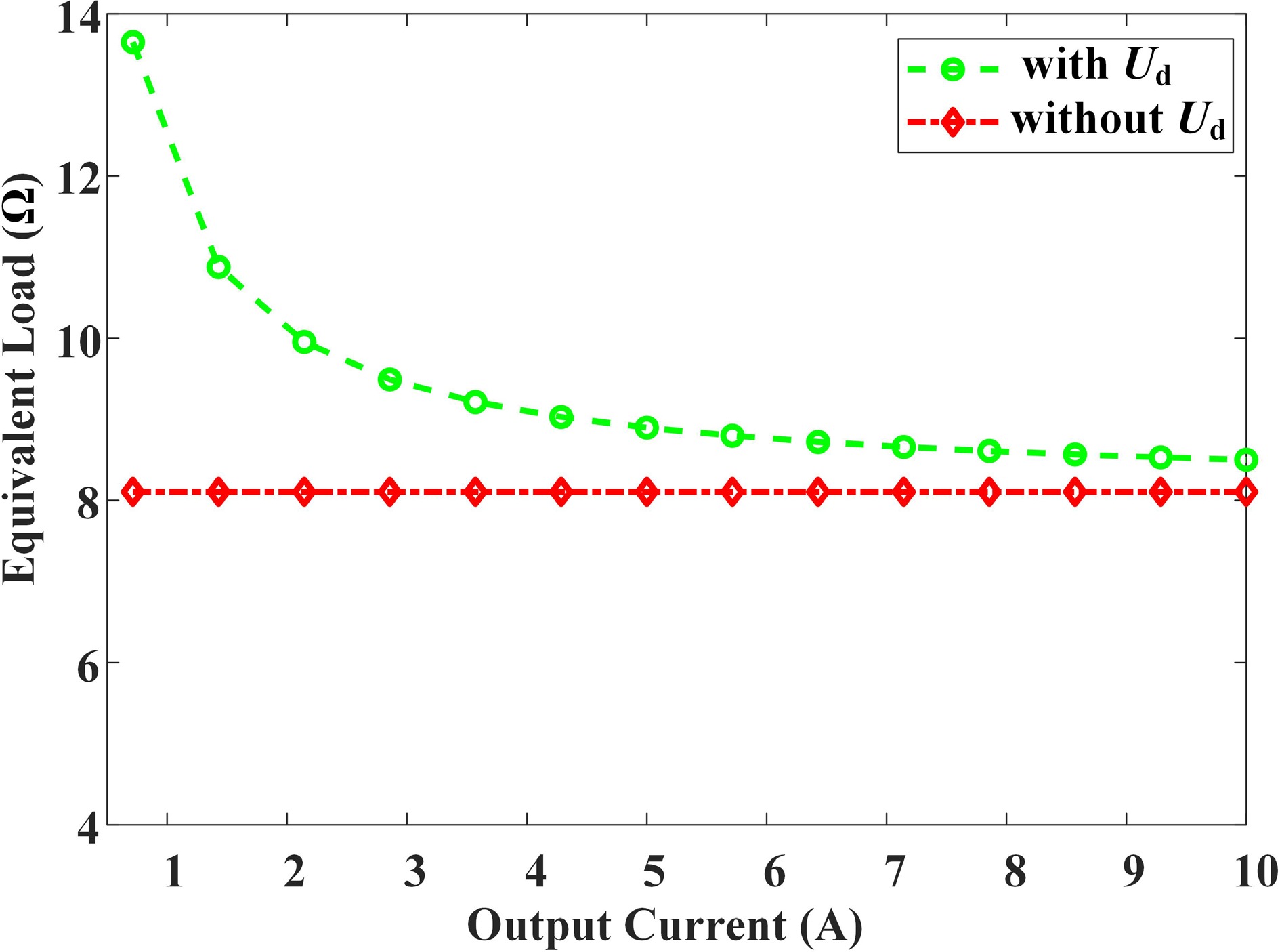
Figure 7.
Relationship between equivalent impedance Req and output current Io.
It can be seen from Fig. 7 that due to the existence of the conduction voltage drop Ud of the diode, the equivalent impedance Req shows nonlinearity. If the existence of Ud is ignored, Req will degenerate into a pure resistor. This feature indicates that in order to accurately calculate the optimal load value of the maximum efficiency point in the UWPT system, the influence of Ud must be incorporated into theoretical modelling in order to precisely push to the maximum efficiency operating conditions of the UWPT system.
Parameter design of the coupling mechanism
-
Transmitting coil: The transmitting side structure is circular with an outer diameter of 55 mm.
Receiving coil: The receiving side structure is circular with an outer diameter of 55 mm.
To ensure optimal quality factor Q and coupling coefficient k for the transmitting and receiving coils under a maximum outer diameter of 55 mm, COMSOL simulation software is used to perform analyses on different coil turn designs. As shown in Fig. 8a–d, the number of coil turns was set to 4, 8, 10, and 12 sequentially. As the turn count increases, the coil's inner diameter decreases continuously. Combining with Fig. 9, it can be seen that although the self-inductance and mutual inductance of the coil continue to increase with the rising of the number of turns, the coupling coefficient between the transmitting coil and the receiving coil exhibits sharp initial growth followed by saturation. This indicates that the increase in the number of turns has a diminishing effect on the improvement of the coupling efficiency, and more turns will also lead to an increase in the parasitic resistance of the coil. Therefore, to achieve the best transmission capability of the coupling mechanism, a 9-turn configuration is selected, where the inner diameter equals approximately 50% of the outer diameter. This proportion balances coupling efficiency against parasitic losses.
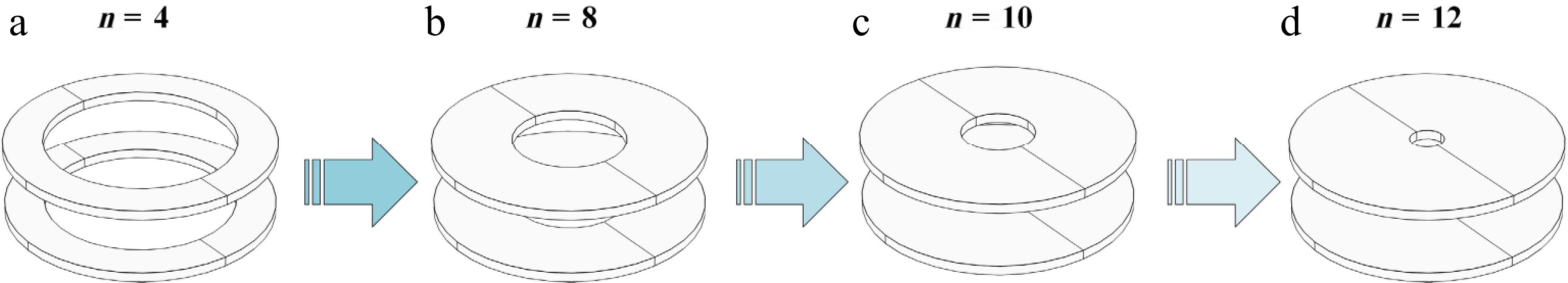
Figure 8.
Relationship between coupling mechanisms and variations in turn number.
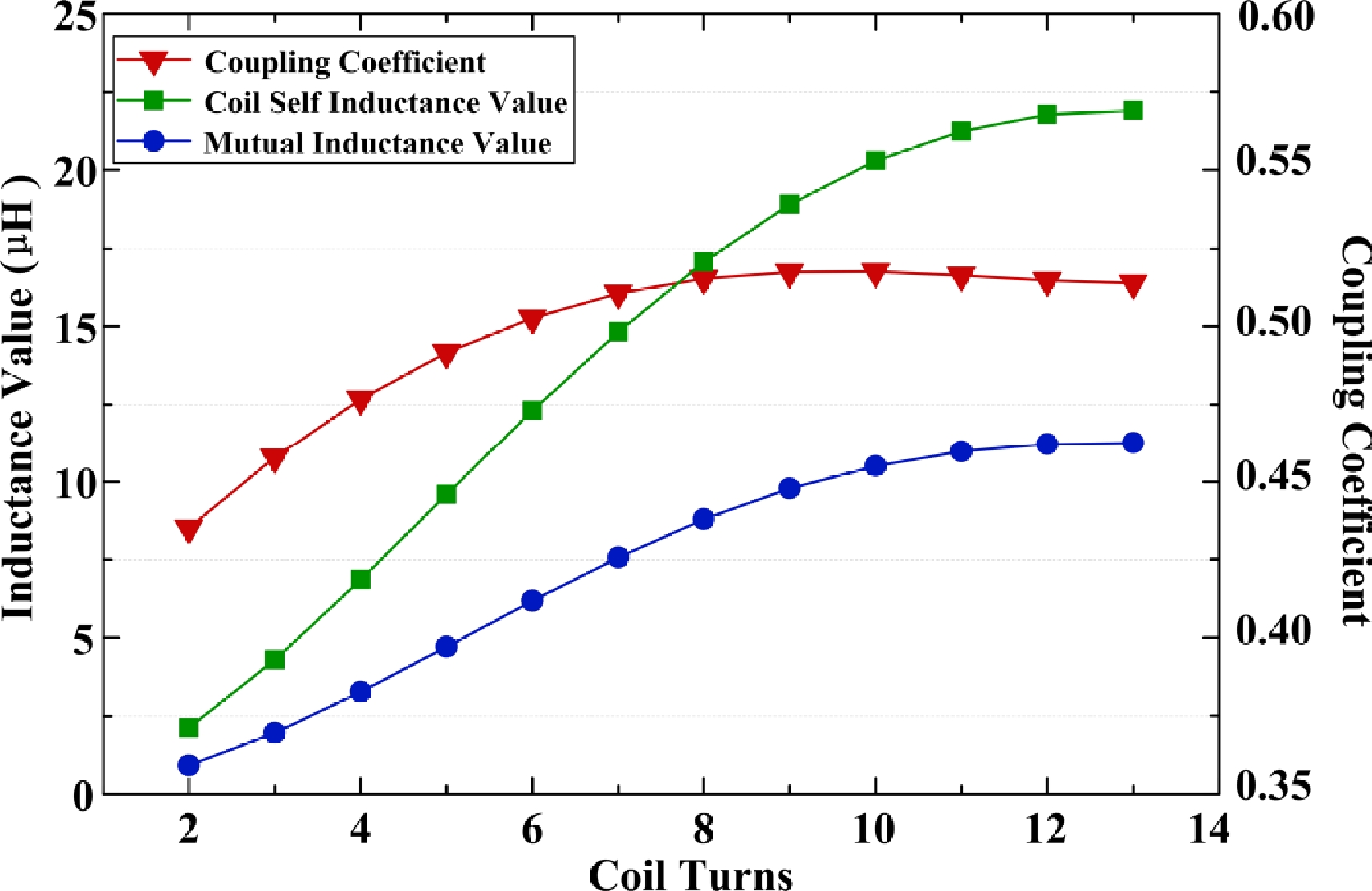
Figure 9.
The relationship between system self-inductance, mutual inductance, coupling coefficient, and number of turns.
Based on the above analysis, the coupling mechanism proposed in this paper is designed as shown in Fig. 10a. The coil uses a double-layer stacked winding, with a ferrite core attached to its bottom. To compare the benefits of the ferrite core scheme, a coupling mechanism without a ferrite core (Fig. 10c) was developed. Figure 10b and d show the magnetic field distribution of the ferrite-core-attached and ferrite-core-free coupling mechanisms, respectively. Figure 11 depicts the physical design of the coupling mechanism. The parameters of ferrite cores are shown in Table 1.
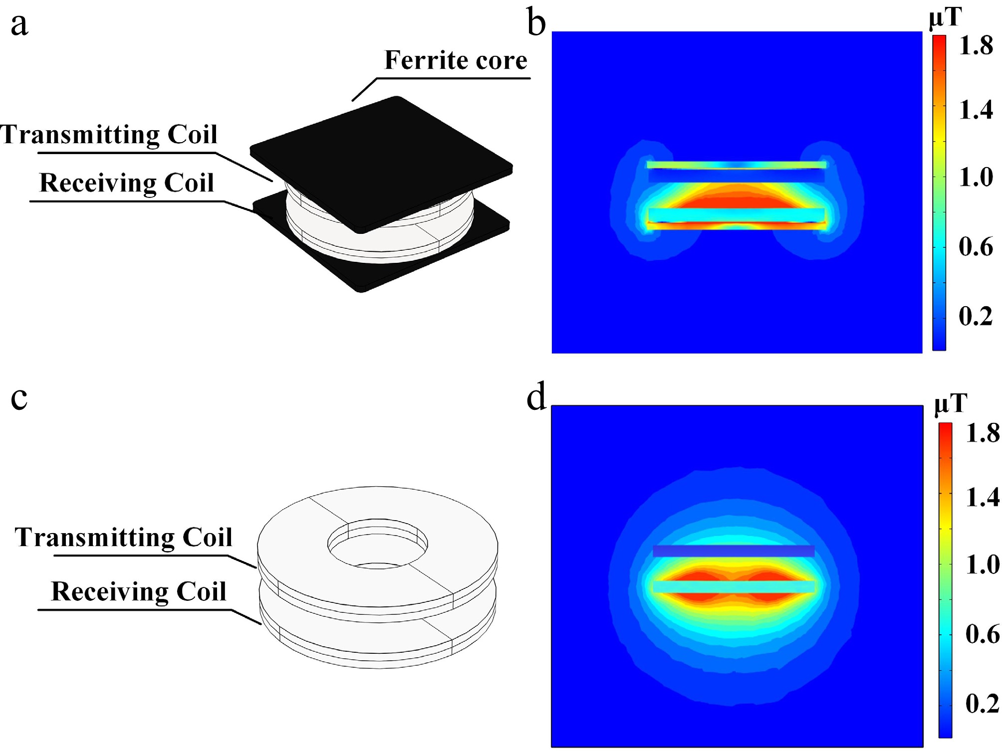
Figure 10.
Influence of ferrite core on magnetic flux density distribution. (a) Coupling mechanism with ferrite layer. (b) Magnetic flux density diagram with ferrite layer coupling mechanism. (c) Coupling mechanism without ferrite layer. (d) Magnetic flux density diagram without ferrite layer coupling mechanism.
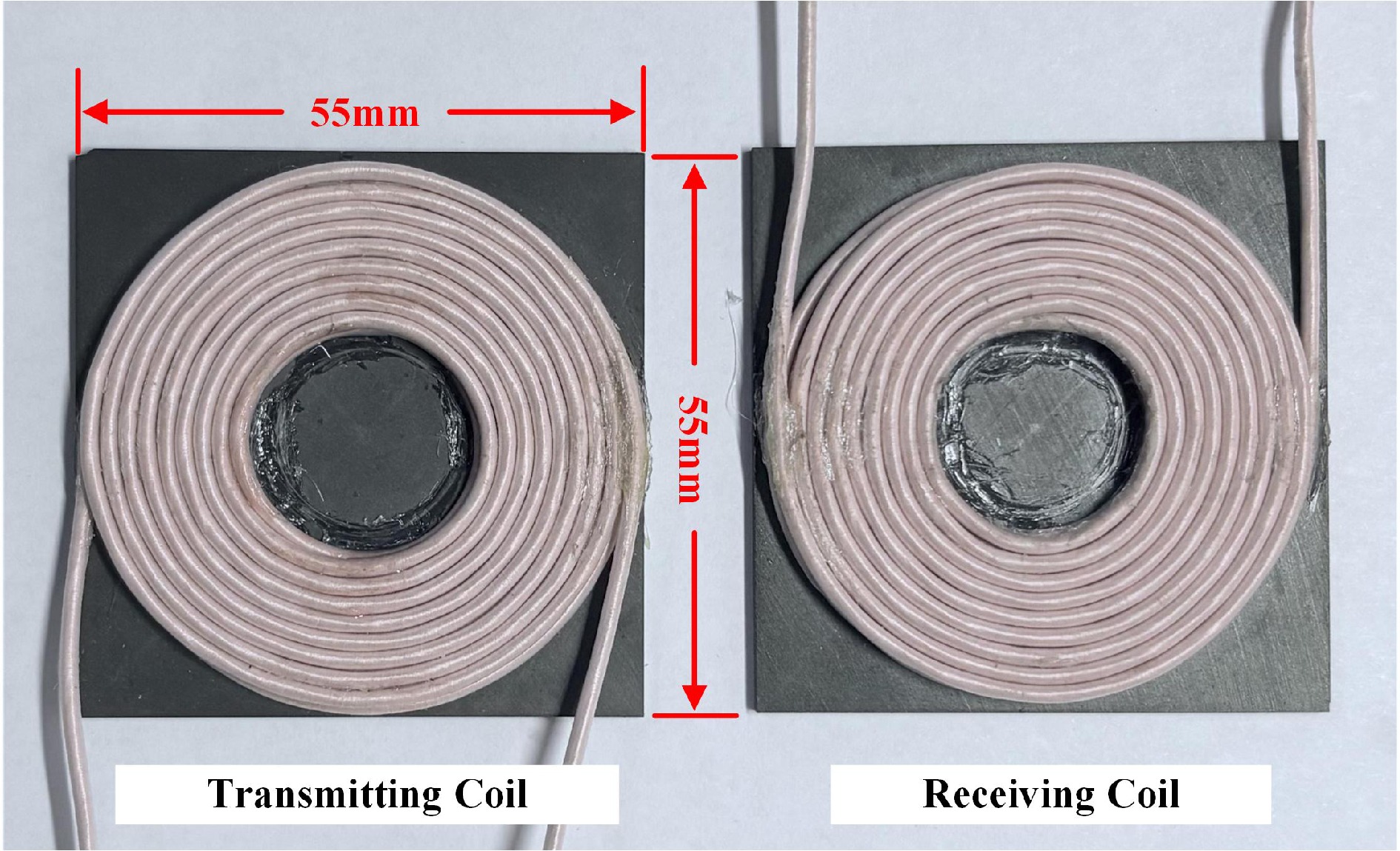
Figure 11.
Physical design of the coupling mechanism.
Table 1. Parameters of ferrite.
Parameters Value Magnetic permeability 3,500 μ0 Transmitting coil 100 × 100 × 10 mm k 0.35 Material PC 95 (MnZn) Receiving coil 100 × 100 × 10 mm d 10 mm d is the transmission distance, k is the coupling coefficient. As shown in Fig. 12, the magnetic field variation curves at a distance of 0.5 cm between the additional ferrite coupling mechanism and the non-ferrite coupling mechanism are presented, respectively. It can be seen that when no ferrite core is added at the bottom (Fig. 12b), the magnetic field leakage is significant. In the brine medium, this triggers a stronger eddy current effect, leading to additional energy loss. Meanwhile, the leaked magnetic field interferes with power electronic circuits, affecting their stable operation. By contrast, after adding a ferrite core, the core's high magnetic permeability forms a magnetic shielding path (Fig. 12a), effectively blocking magnetic field diffusion to the bottom. This not only reduces eddy current losses in the brine medium but also mitigates electromagnetic interference from the leakage field to underlying circuits, significantly enhancing the system's electromagnetic compatibility and energy transmission efficiency in underwater environments.
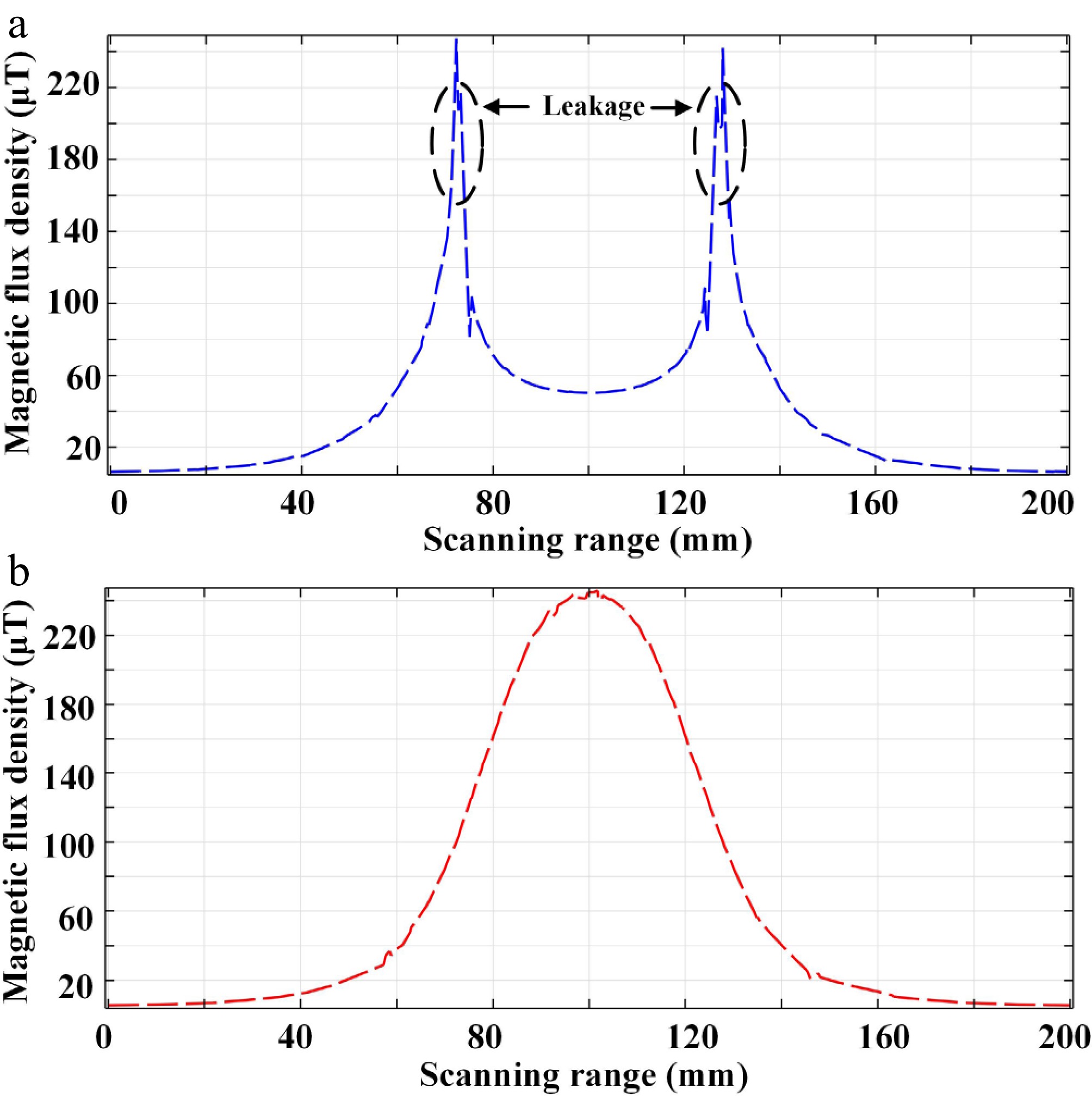
Figure 12.
The curve of magnetic induction intensity variation. (a) With ferrite core. (b) Without ferrite core
-
Based on the analysis in Eq. (11), the optimal equivalent impedance after matching with the resonant compensation network is derived as Ropt. Further analysis shows that when the transmitting and receiving coils have high quality factors QP and QS, their parasitic resistances RP and RS can be neglected. When the transmission frequency f is fixed, fluctuations in mutual inductance M caused by coil offset are the primary variable affecting the optimal load. Thus, substituting Ropt into Eq. (15), and after calculating the voltage drop of the rectifier bridge and converting it, the expression for the actual optimal load is obtained as:
$ {R}_{\text{L}}=\left(\sqrt{\dfrac{{\omega }^{2}{M}^{2}{R}_{\text{S}}}{{R}_{\text{P}}}+R_{\text{S}}^{2}}-\dfrac{4\sqrt{2}{U}_{\text{d}}}{{\text π}{I}_{\text{o}}}\right)\dfrac{{\text π}^{2}}{8} $ (16) The compensation parameters of the transmitting side and the receiving side of the circuit are shown in Table 2.
Table 2. Parameters of the circuit.
Parameters Value Parameters Value Vin 60 V Pout 100 W f 500 kHz Cp 5.06 nF LP 20 μH CS 5.5 nF LS 18 μH RL 39 Ω Experimental results
-
Figure 13 shows the experimental platform in an air medium, and Fig. 14 depicts the underwater experimental platform simulating a 35 ‰ salinity water medium. A DC constant-voltage power supply serves as the system input, and electrical energy is transmitted from the transmitter to the receiver through coupling via a high-frequency magnetic field. An electronic load is used to simulate sensor loads. Thus, undersea wireless power transmission for underwater intelligent sensors is achieved.
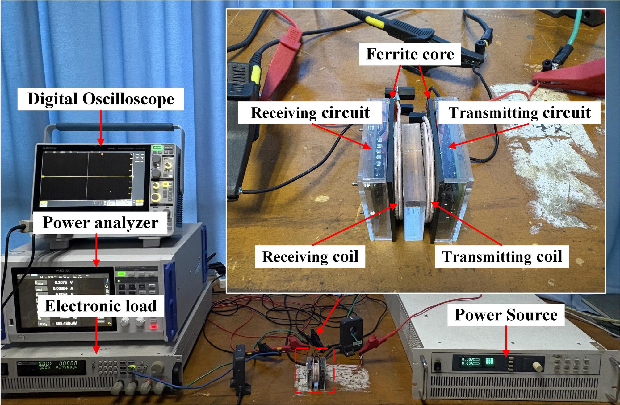
Figure 13.
Experimental setup in air.
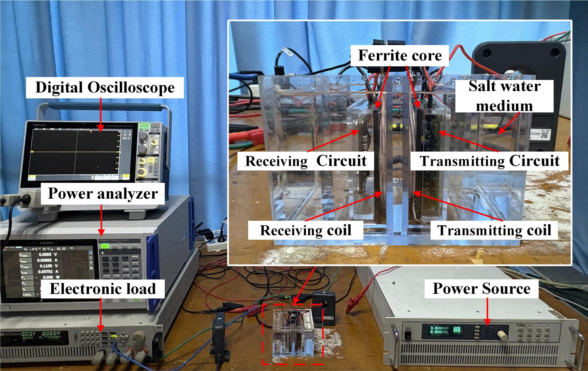
Figure 14.
Experimental setup in salt water.
For high power density applications, integrating and miniaturizing the transmitting circuit is crucial. Figure 15 shows the high-frequency inverter used at the transmitting end. The third-generation wide-bandgap semiconductor gallium nitride (GaN) is used as the switching device to achieve high-frequency power conversion with low losses.
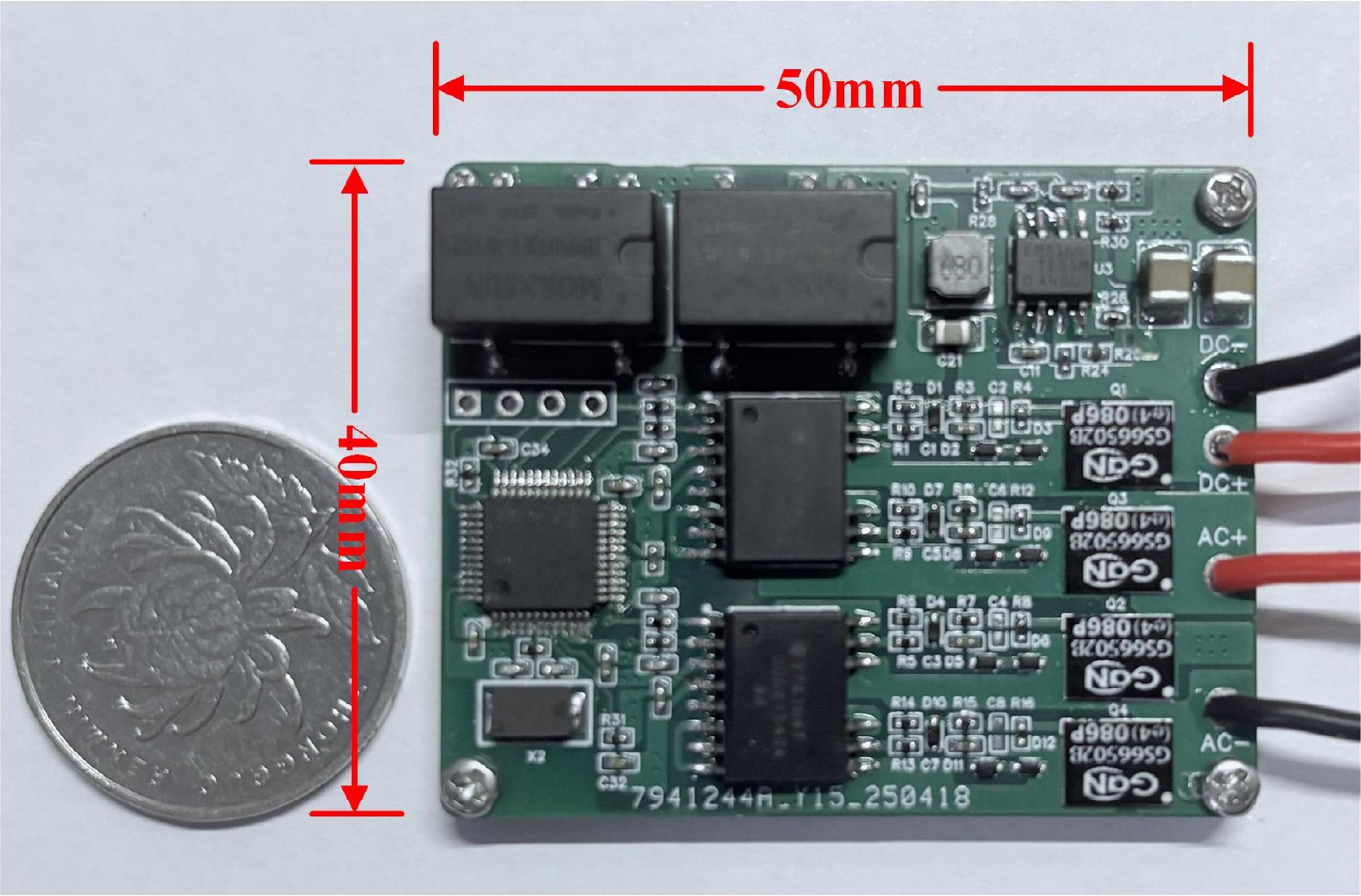
Figure 15.
Physical design of a high-power-density integrated high-frequency inverter.
The circuit design consists of an auxiliary power supply circuit, a control circuit, a drive circuit, and a switching bridge arm. A DC constant-voltage source serves as the system's input power. The high-frequency inverter performs DC/AC conversion to generate high-frequency square waves. As shown in Fig. 16, the waveforms of the switching tube's driving voltage Vgs and drain-source voltage Vds are depicted. Before the driving signal Vgs switches from low to high, the switching tube's drain-source voltage Vds has already dropped to 0 V. Thus, ZVS is achieved in the system, avoiding substantial switching losses and improving system efficiency.
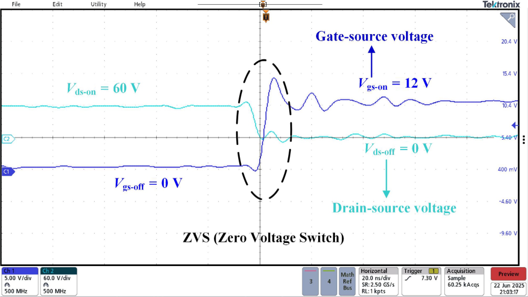
Figure 16.
The driving voltage and drain-source voltage waveforms of the transistor.
The performance of the proposed UWPT system in an air environment was verified experimentally using the platform shown in Fig. 13. After high-frequency inversion, energy passes through the compensation network to achieve ZPA transmission. Fig. 17 presents the primary and secondary voltage and current waveforms during system operation. The transmitting side current and voltage are in phase with their receiving side counterparts, confirming ZPA transmission. Thus, the correctness of the proposed system parameter design method is validated.
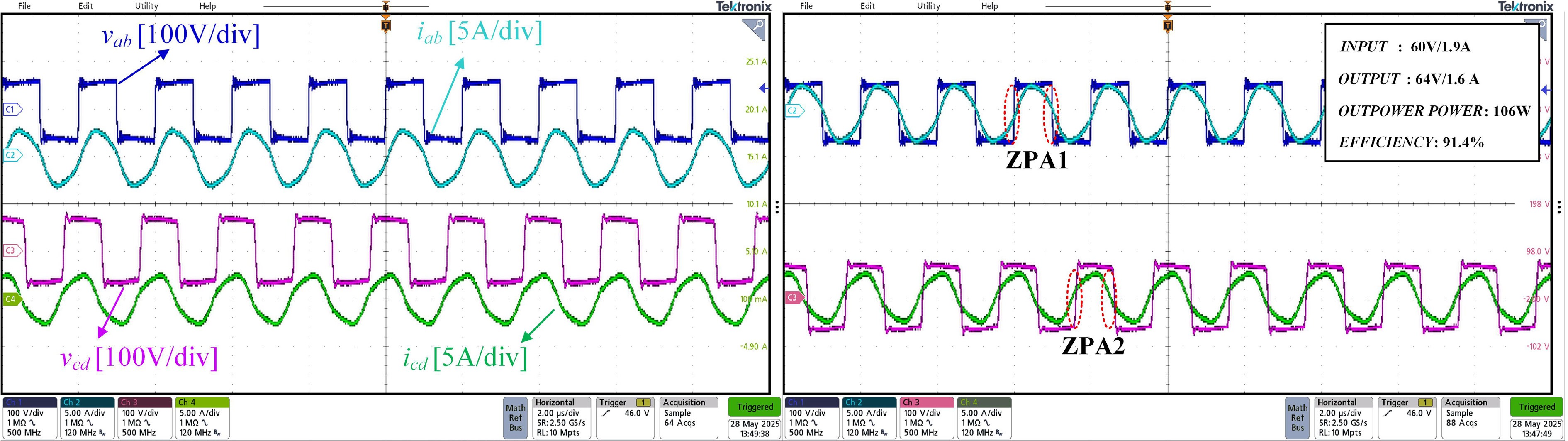
Figure 17.
The voltages and currents on the transmitting and receiving sides of the system.
Figure 18 shows the system's anti-misalignment capability test. As described in Eq. (16), mutual inductance variation, due to offset between coupling coils, alters the load at the optimal efficiency point. Effective anti-misalignment capability maintains peak efficiency despite positional disturbances. When a relative coil offset occurs, reduced mutual inductance tends to increase the current, but the system maintains resonance even at a maximum offset of 20 mm, ensuring stable power transmission during seawater fluctuations.
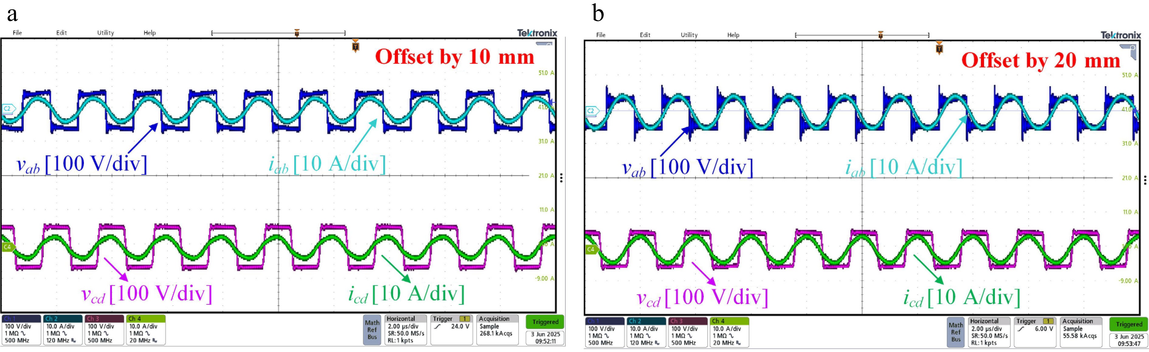
Figure 18.
Voltage and current on the transmitting and receiving sides when the relative position between coils changes. (a) Relative position of the coils is offset by 10 mm. (b) Relative position of the coils is offset by 20 mm.
Furthermore, output load fluctuations during power transmission require explicit consideration. To validate the system's constant-current output capability, Fig. 19 demonstrates voltage and current responses under load transients. When the load suddenly decreases from 40 Ω to 20 Ω, the output power is switched from 106 to 52 W. The system exhibits fast dynamic response and maintains constant current output characteristics. There are no significant voltage or current spikes during transient overshoots, thereby avoiding device damage from overshoots.
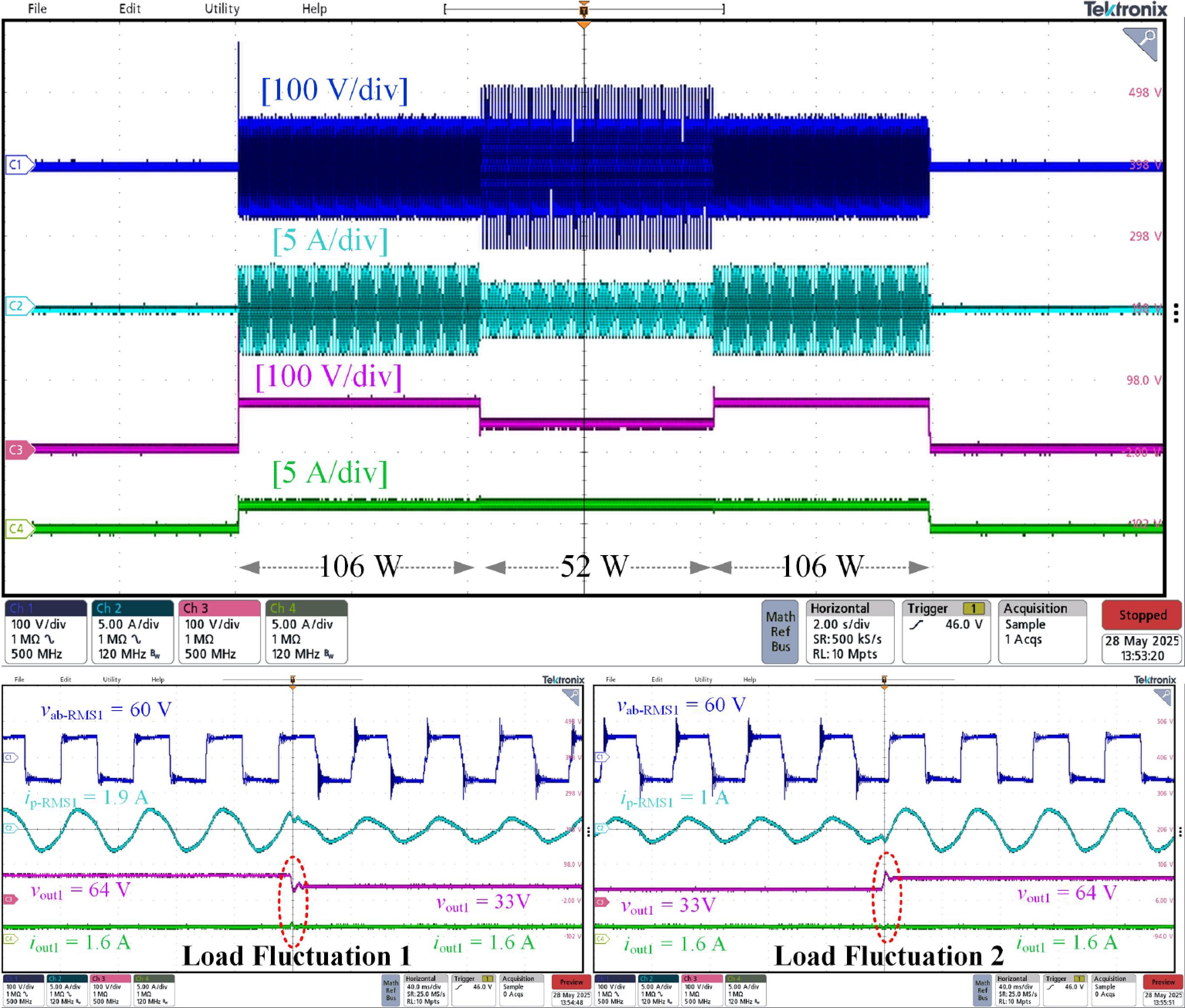
Figure 19.
Output voltage and current in constant current operation (load fluctuation).
The proposed system achieves an efficiency of approximately 91.4% under a 100 W operating power. To simulate the seawater environment, 35‰ salinity brine was prepared.
The higher electrical conductivity of the seawater medium compared to air causes partial energy conversion into heat loss, leading to an efficiency drop of approximately 2%. As shown in Fig. 20, the maximum efficiency points under optimal load in both seawater and air are presented.
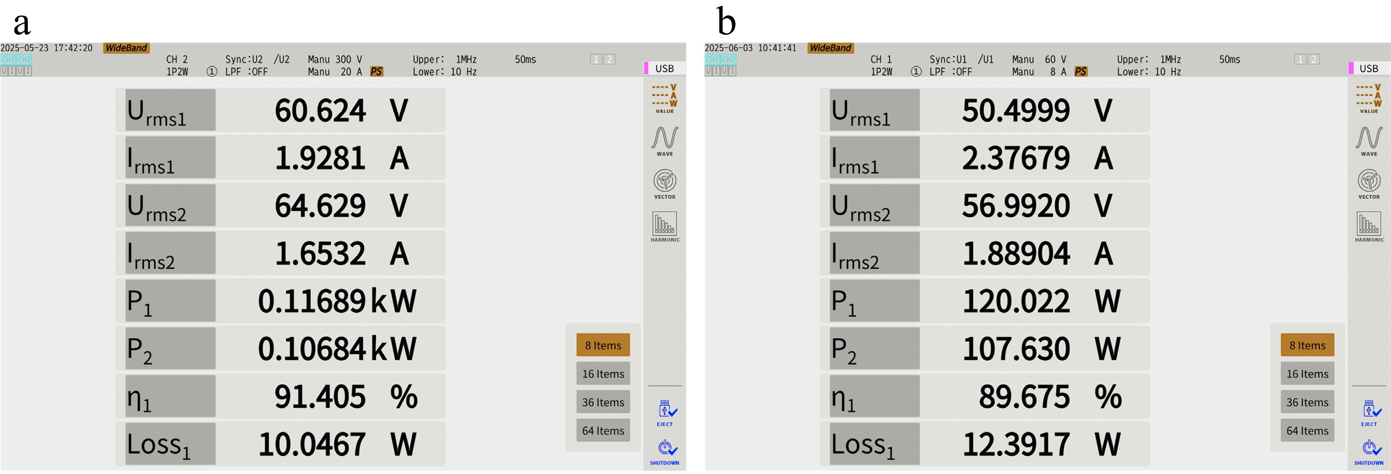
Figure 20.
(a) System operation efficiency (air). (b) System operation efficiency (salt water).
Table 3 compares this work with existing studies. Specifically, the comparison focuses on power density regarding the planar dimensions of the coupling mechanism. This paper presents a high-power-density integrated UWPT system. Compared with the state-of- the-art studies, the higher power density was achieved with a higher efficiency. The 500 kHz resonant switching frequency was adopted to improve the power density with the help of GaN/Mosfets. Additionally, methods such as ferrite core integration and optimal load calculation are used to improve transmission efficiency, addressing energy loss due to eddy currents in underwater environments.
Table 3. Comparison with state-of-art works.
Reference Ferrite core Feature Coils size (mm) Power (W) PD (W/cm2) Efficiency An underwater inductive power transfer system with a compact receiver and reduced eddy current loss[24]. Yes CV Tx: 200 × 200;
Rx: 200 × 200300 0.375 88.6% (water) Design and verification of adaptive CC/CV mode switching wireless power transfer system for UAVs based on high switching frequency single-switch LC inverter[25]. No CV&CC Tx: 350 × 350;
Rx: 250 × 250100 0.05 91.6% (air) Undersea simultaneous wireless power and data transfer system with extended communication distance and high rate[26]. Yes CV Tx: 150 × 150;
Rx: 150 × 150500 1.11 90% (water) A dual-output AC–AC converter for double transmitter wireless power transfer systems[27]. Yes CC&AM Tx: 300 × 300 (2s);
Rx: 280 × 280384 0.22 93.7% (air) This work Yes CC&AM Tx: R = 27.5;
Rx: R = 27.5100 2.1 91.4% (air);
89.6% (seawater)Notes: R is the diameter of a circle, h is the height of the cylinder, CC is the constant current feature, CV is the constant voltage feature, AM is the anti-migration feature, 2s indicates that two groups of coils, PD indicates Power Density. In summary, the proposed undersea wireless power transfer system was experimentally validated. The experimental results are in good agreement with the theoretical analysis from the simulation, thus confirming the system's superior performance.
-
This paper proposes a high-power-density integrated undersea wireless power transfer system for underwater intelligent sensors. The compact, modular design integrates components like high-frequency inverters and control circuits into a small form factor, suitable for space-constrained underwater devices. Utilizing AUVs as transmitters, the system powers seabed sensors and relays, improving deployment flexibility and autonomy in ocean observation networks. A 100 W prototype demonstrates key innovations: ZVS minimizes losses at medium-to-low power; nonlinear rectifier load modeling improves optimal load prediction; coil geometry is optimized to withstand ocean currents; and ferrite cores suppress leakage fields, enhancing coupling efficiency and reducing interference. Experimental results show 91.4% efficiency in air and 89.6% in saline water, validating the system's potential to provide reliable, flexible power for advanced underwater sensing and monitoring infrastructure.
-
The authors confirm contribution to the paper as follows: study conception and design, data collection, analysis and interpretation of results and draft manuscript preparation: Xing D; writing − review and editing: Yang L; supervision: Wen H, Zhao Y, Yang T, Sun Y, Zhang A, Tong X. All authors have read and agreed to the final version of the manuscript.
-
All data generated or analyzed during this study are included in this published article.
-
This work was supported by the National Natural Science Foundation of China (Grant Nos U2106218 and 52267019), the Foundation of The International Science and Technology Cooperation Center of Renewable Energy and Hybrid Power, Shaanxi, the China Postdoctoral Science Foundation (Grant No. 2023MD734218), the Key Research and Development Plan Project of Shaanxi Province (Grant No. 2024GX-YBXM-255), the Qin Chuang Yuan 'Scientist + Engineer' Team Building Project of Shaanxi Province (Grant No. 2024QCY-KXJ-034), the Natural Science Basic Research Plan in Shaanxi Province of China (Grant No. 2024JC-YBQN-0618), Shaanxi Provincial Department of Education Service Local Special Project Program (Grant No. 24JC067), and the Xi'an Science and Technology Plan Project (Grant Nos 23GXFW0069 and 24LLRHZDZX0007).
-
The authors declare that they have no conflict of interest.
- Copyright: © 2026 by the author(s). Published by Maximum Academic Press, Fayetteville, GA. This article is an open access article distributed under Creative Commons Attribution License (CC BY 4.0), visit https://creativecommons.org/licenses/by/4.0/.
-
About this article
Cite this article
Yang L, Xing D, Wen H, Zhao Y, Yang T, et al. 2026. High power density integrated wireless power transfer method for underwater intelligent sensors. Wireless Power Transfer 13: e008 doi: 10.48130/wpt-0025-0036 

High power density integrated wireless power transfer method for underwater intelligent sensors
- Received: 13 September 2025
- Revised: 28 November 2025
- Accepted: 11 December 2025
- Published online: 25 March 2026
Abstract: This paper proposes a high-power-density integrated undersea wireless power transfer (UWPT) system for underwater intelligent sensors, which features anti-offset capability and electromagnetic shielding compatibility. Firstly, the high-frequency inverter designed for the UWPT system integrates auxiliary power supplies, control circuitry, driving components, and semiconductor switching devices. By employing zero-voltage switching (ZVS) technology to minimize high-frequency switching losses, the design enables a more compact structure and enhanced reliability. Secondly, to achieve high transmission efficiency, this paper establishes a nonlinear rectifier bridge load equivalent model based on the proposed topology. It reveals the mechanism by which the rectifier diode voltage drop affects load conversion and quantitatively analyzes how system efficiency varies with load. This analysis helps reduce calculation errors in determining the optimal load. Furthermore, the adoption of ferrite cores enhances the coupling coefficient and reduces eddy current losses resulting from the leakage of high-frequency alternating magnetic fields in the circuit. Finally, a 100 W prototype is built with a 500 kHz switching frequency to validate the proposed design. Experimental results demonstrate that the UWPT system exhibits strong robustness in both air and salt water environments. The maximum efficiencies achieved are 91.4% in air, and 89.6% in salt water.