-
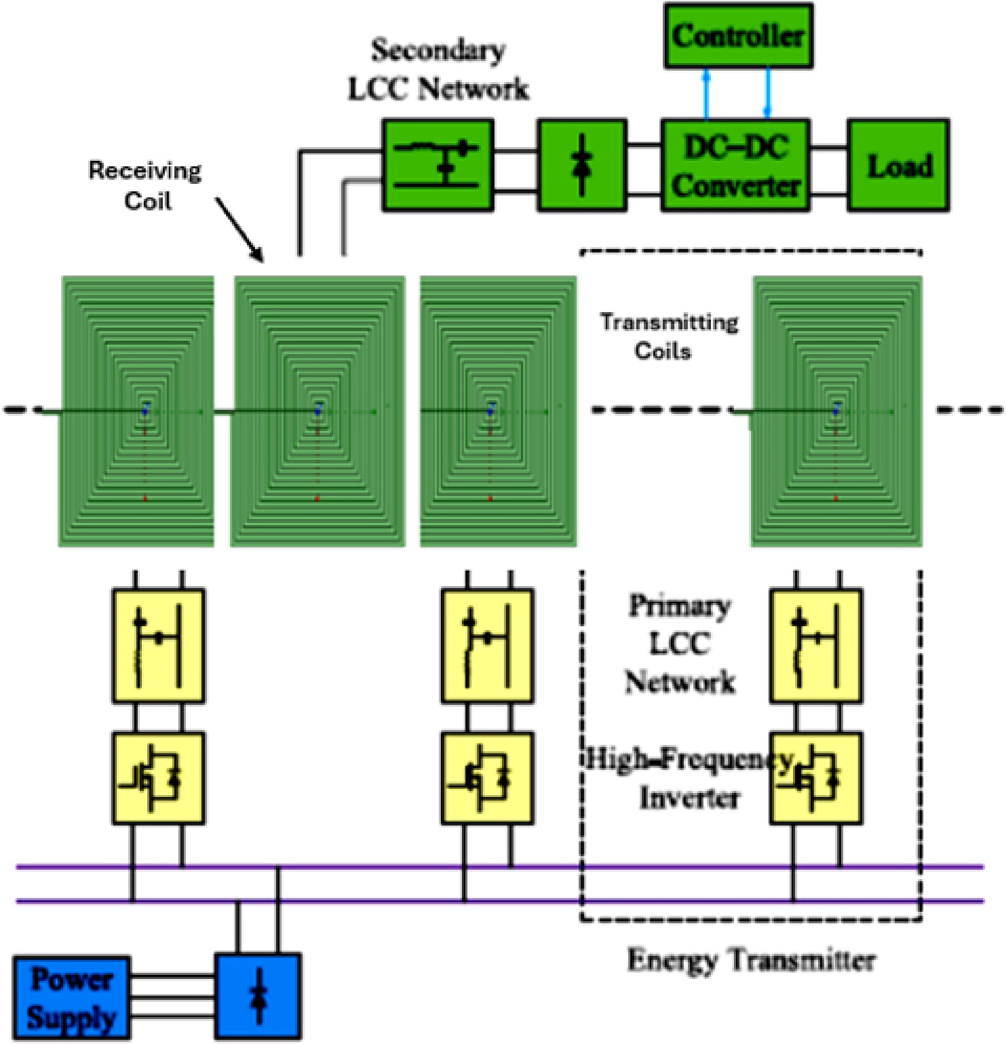
Figure 1.
Schematic diagram of the DWPT system.
-
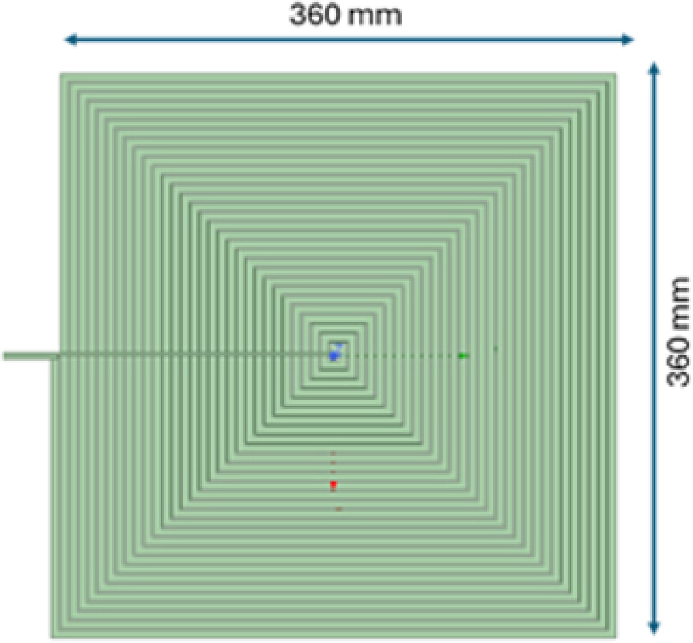
Figure 2.
Conception of a rectangular coil modeled using software.
-
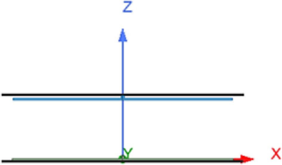
Figure 3.
Transmitting and receiving coil with ferrite.
-
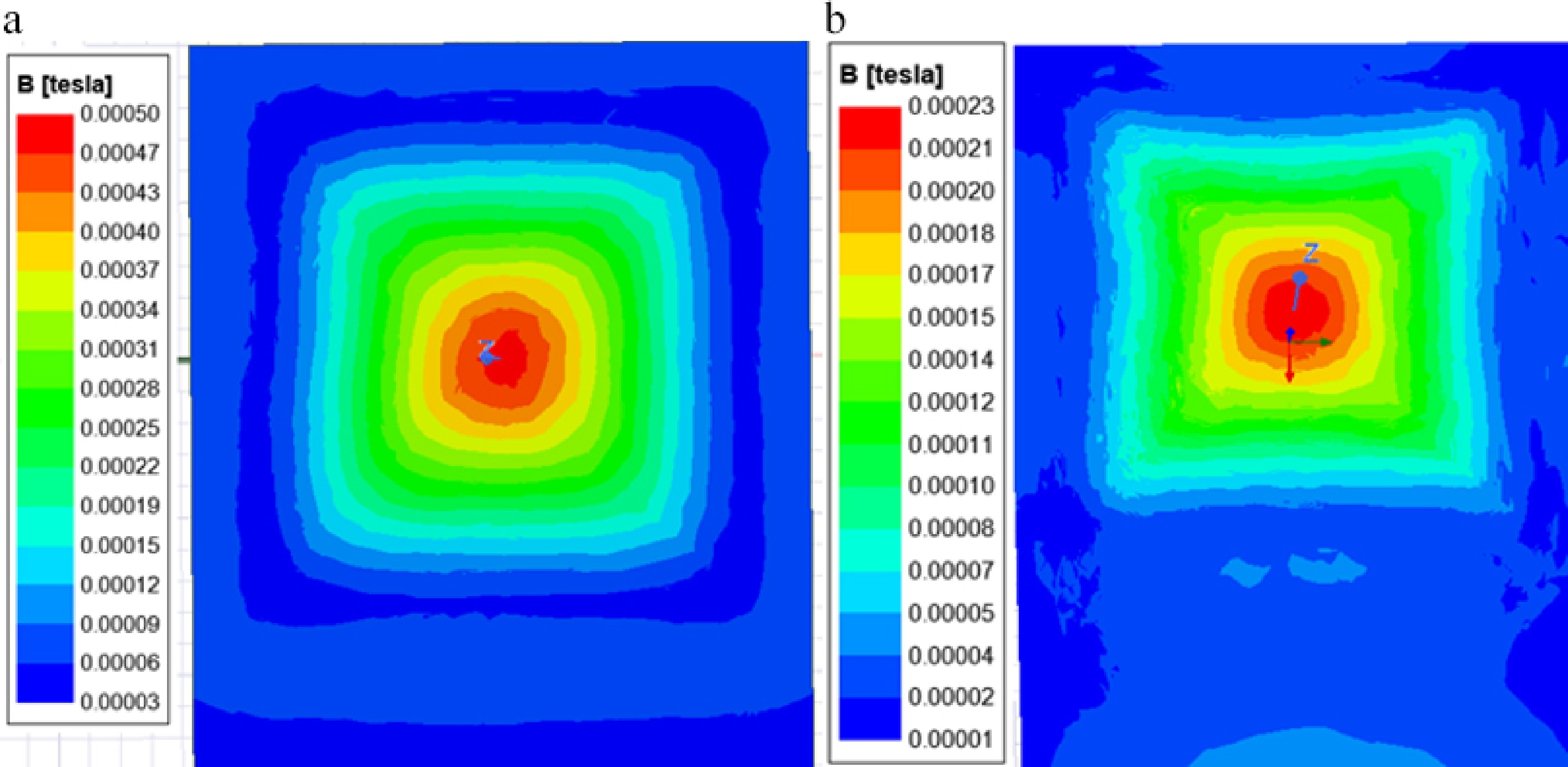
Figure 4.
The magnetic field distribution on the YZ plane was simulated under the same conditions: (a) with ferrite, (b) without ferrite.
-
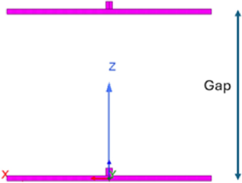
Figure 5.
Distance between the transmitter and receiver coil along the z axis.
-
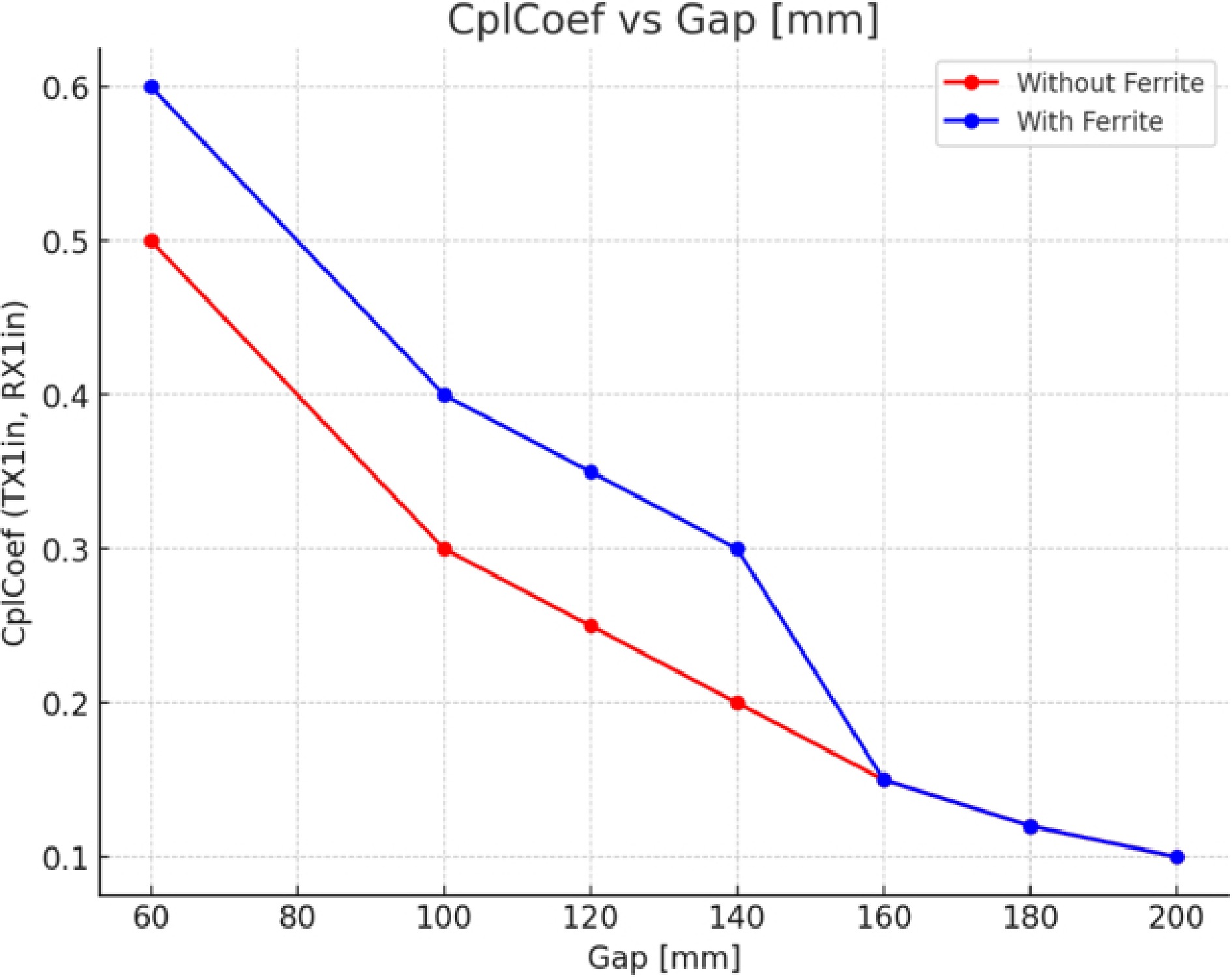
Figure 6.
Coupling factor for different gap values.
-
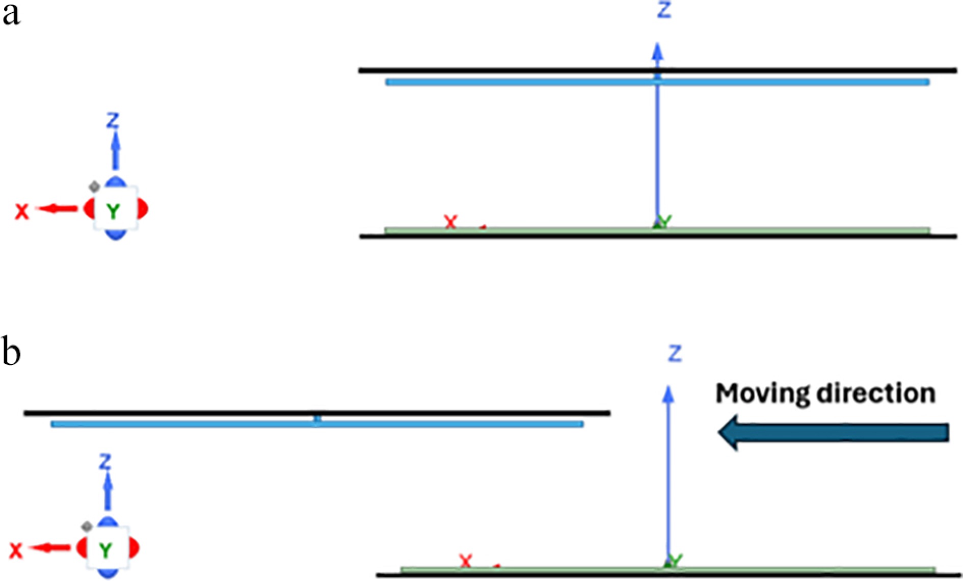
Figure 7.
Misalignment of receiver coil: (a) dist_x = 0, (b) dist_x = 240 mm.
-
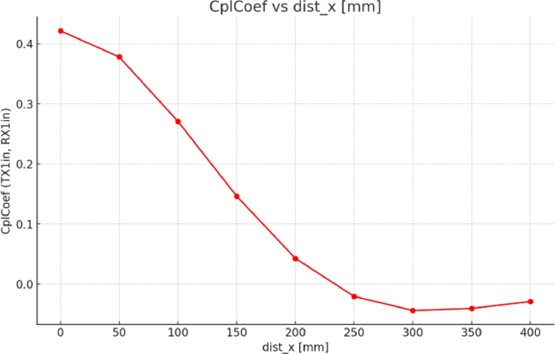
Figure 8.
Coupling factor for different dist_x values.
-
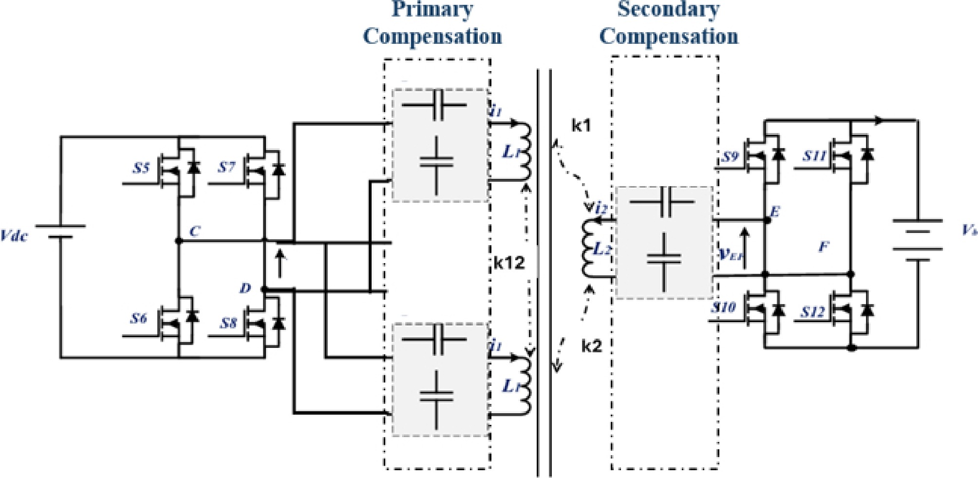
Figure 9.
circuit topology of a DWPT.
-
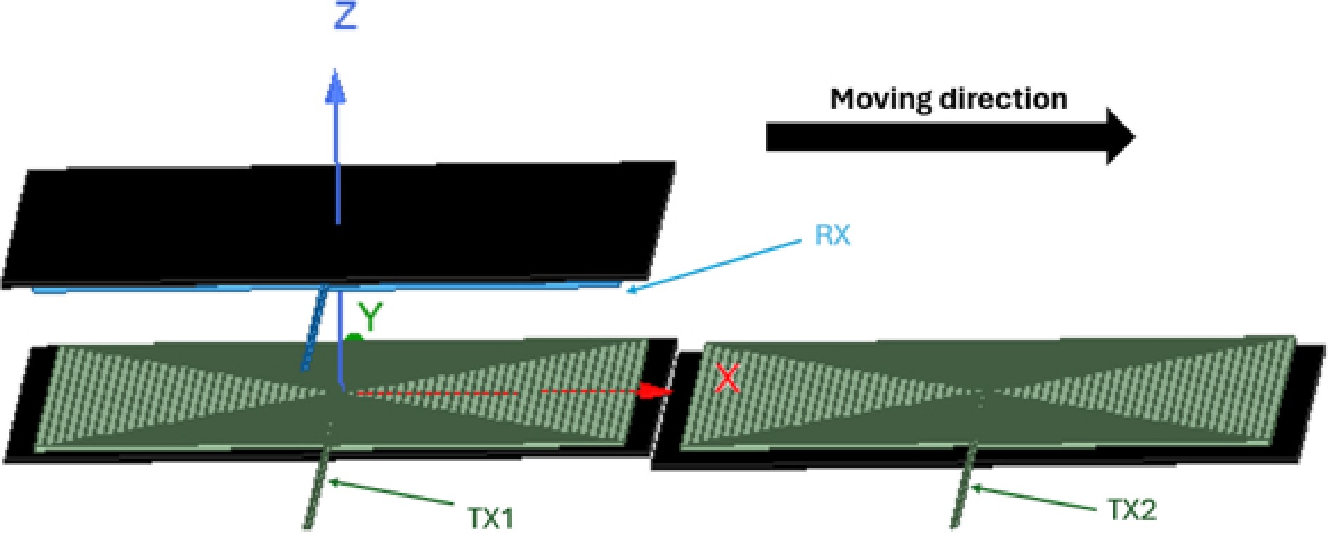
Figure 10.
Segmentation of transmitter coils.
-
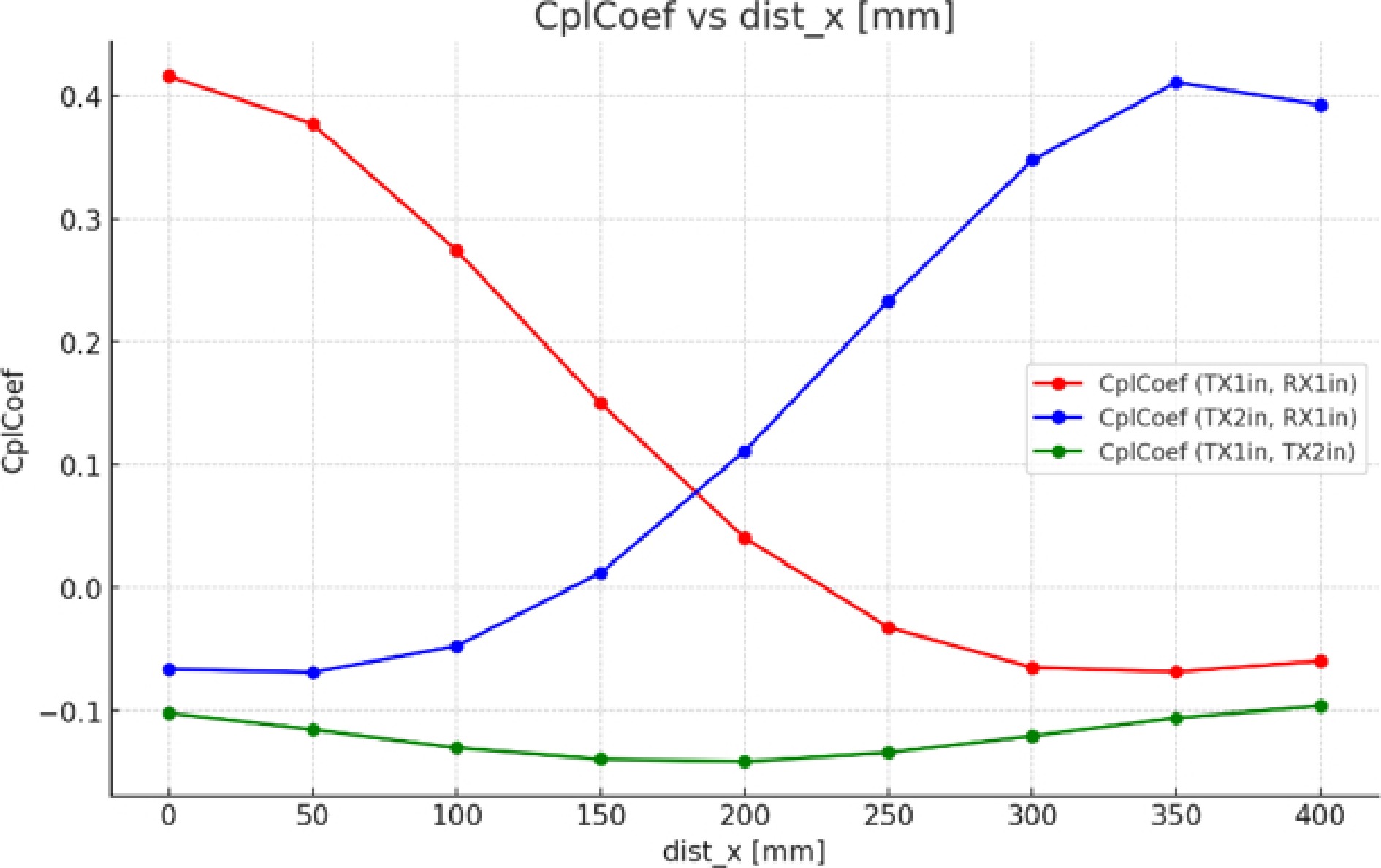
Figure 11.
Coupling factors for different coils.
-
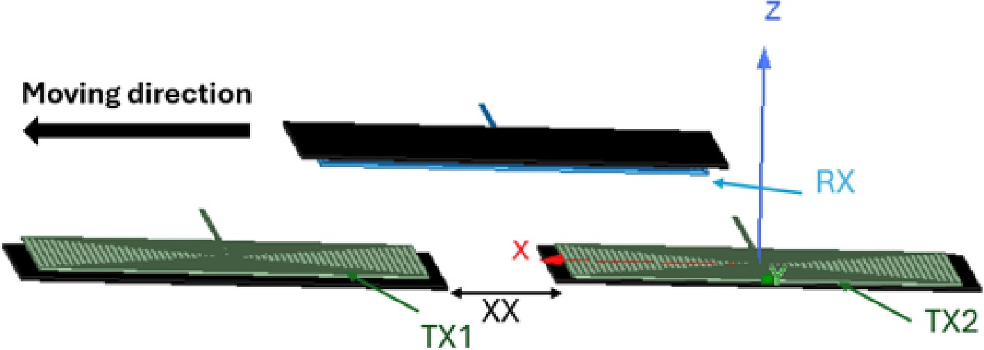
Figure 12.
Segmentation of transmitter coils with different XX values.
-
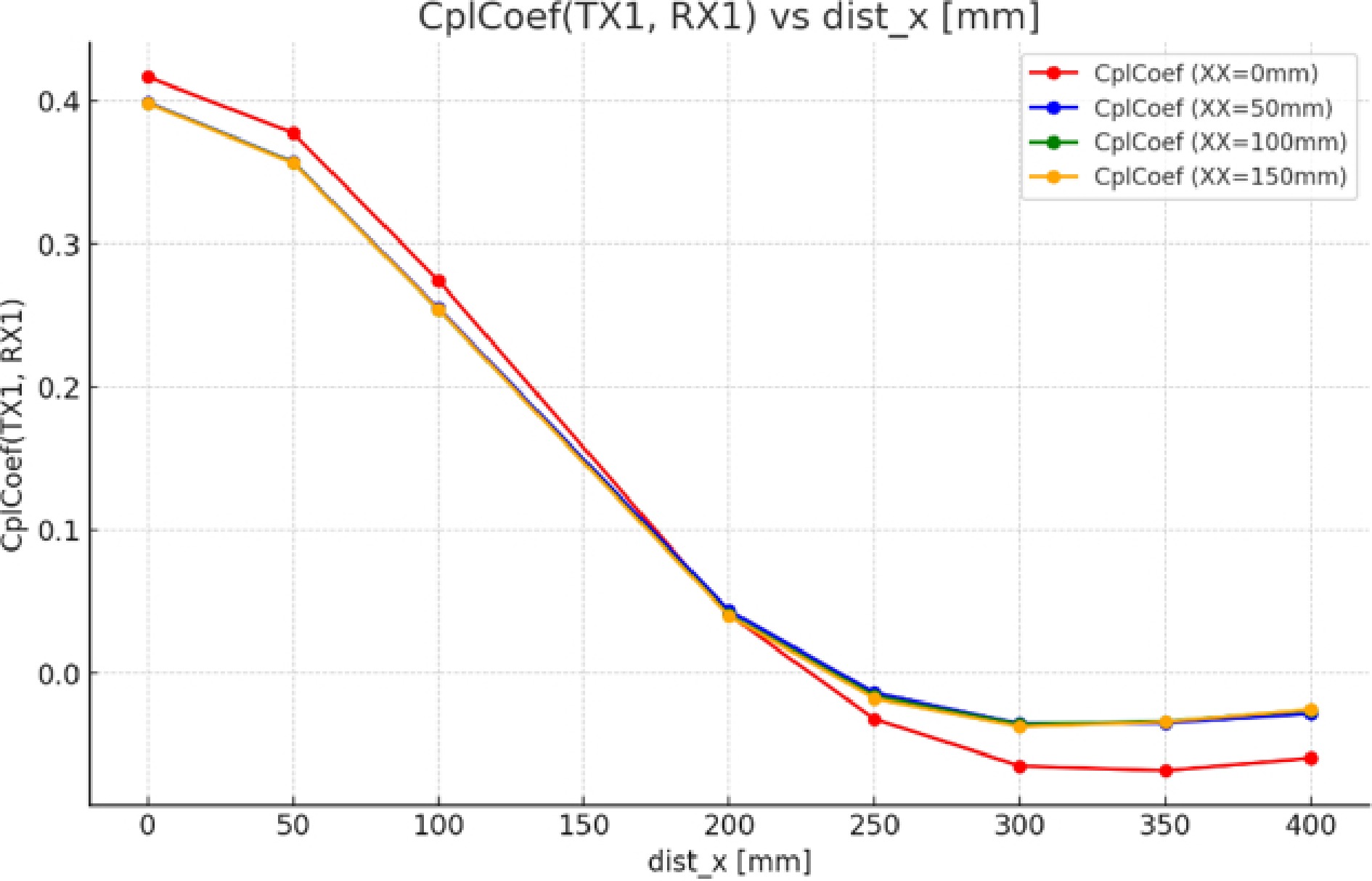
Figure 13.
Coupling factor between TX1/RX for different values of XX.
-
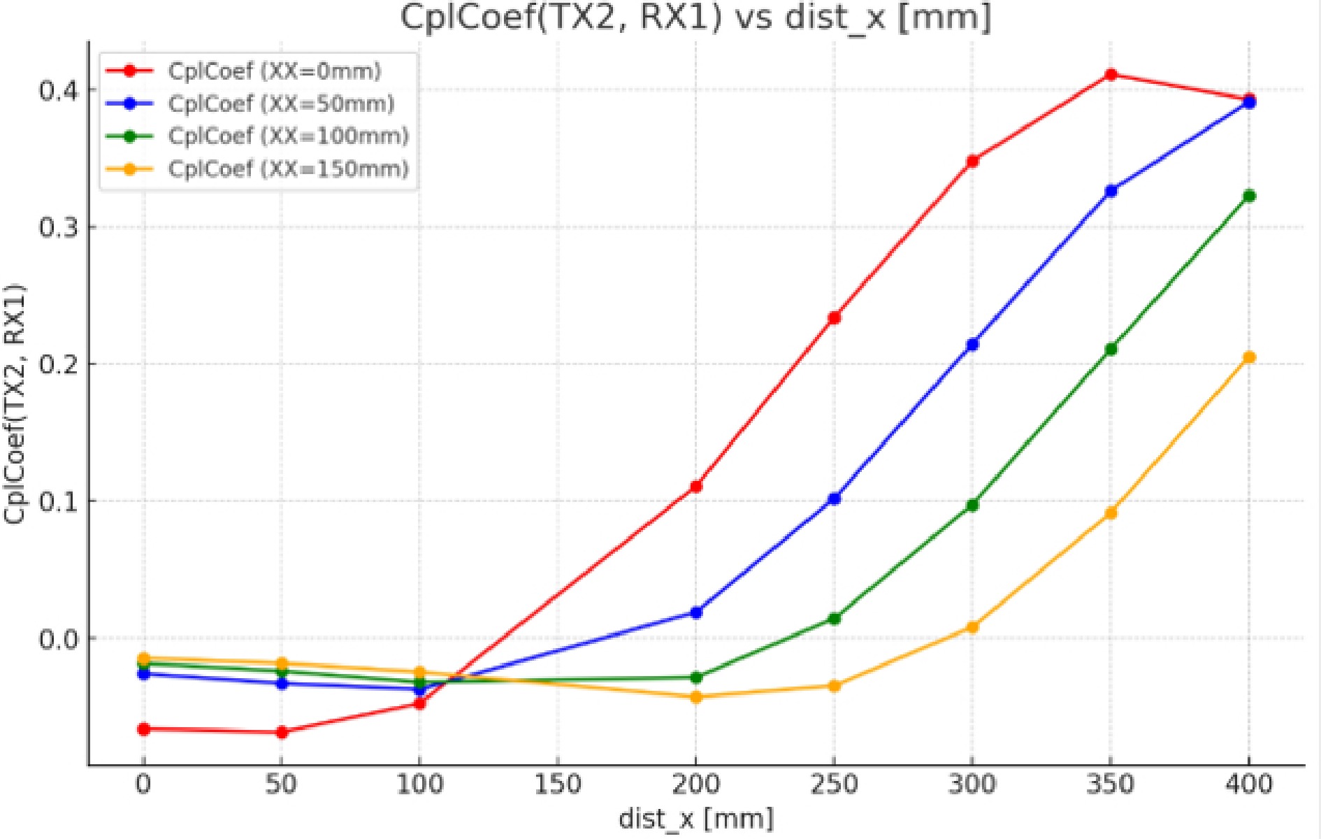
Figure 14.
Coupling factor between TX2/RX for different values of XX.
-
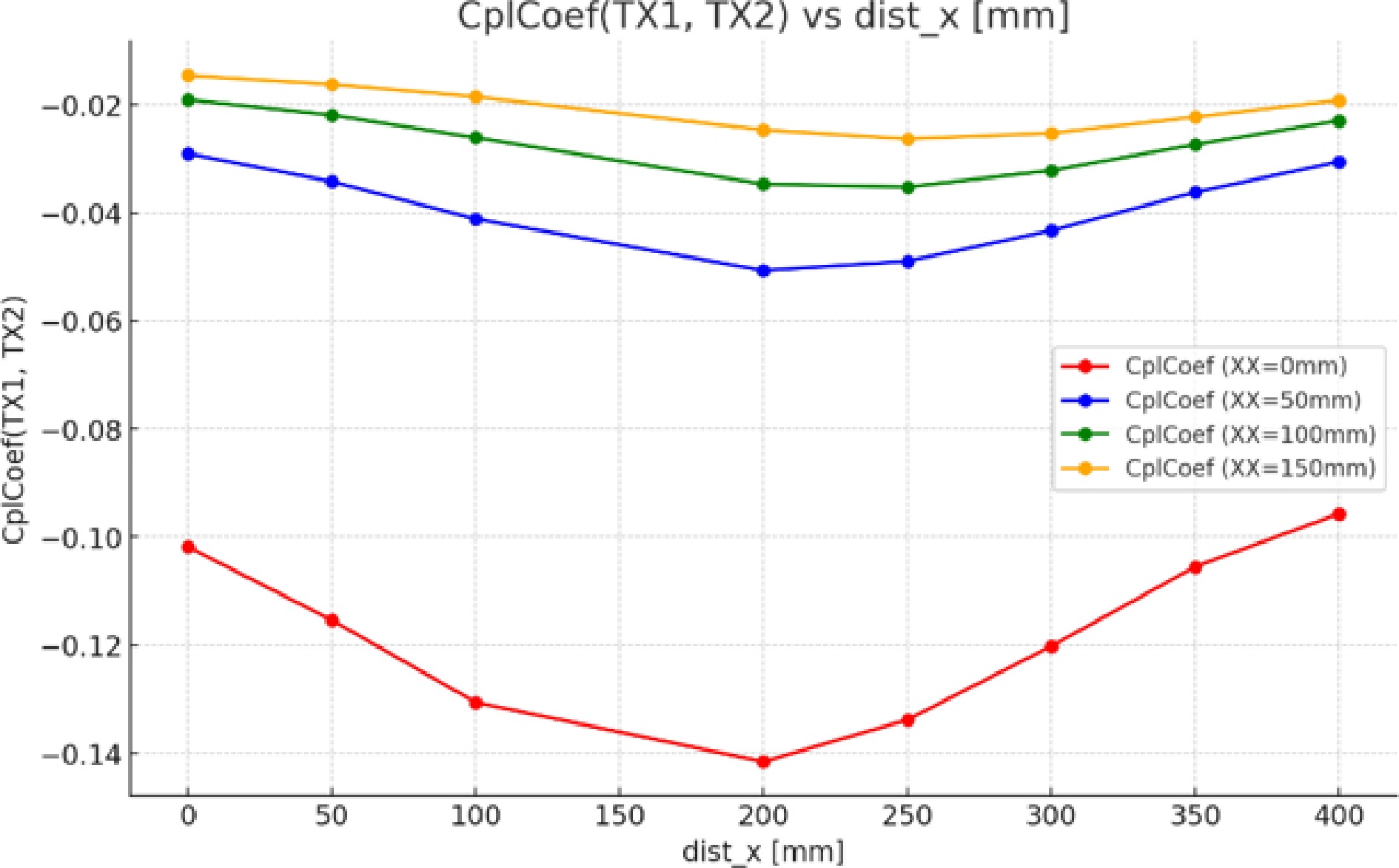
Figure 15.
Coupling factor between TX1/TX2 for different values of XX.
-
Gap (mm) Without ferrite With ferrite L(µH) Tx1 M(µH) Tx1/Rx L(µH) Tx1 M(µH) Tx1/Rx 100 136 39 244 95 120 135 31 237 74 Table 1.
Inductance of the rectangular coils.
Figures
(15)
Tables
(1)