












-
Climate change is one of the major challenges facing the world today. To reduce its harmful effects, it is crucial to review the modes of transport we use, given that this sector is one of the biggest emitters of greenhouse gases[1]. Electric vehicles offer a promising solution: these cars, powered by rechargeable batteries, generate no pollution when they're running, reduce carbon emissions, and the electricity used to recharge them comes from renewable sources offer better use of available energy and more efficiency than traditional combustion engines[2,3]. However, to ensure that electric vehicles become normalized and adapted on a large scale, an appropriate recharging infrastructure needs to be established, so electric chargers are very important in this process[4−7]. Currently, many chargers are of the wired type and are installed at home or in public places. Although they are frequently used, their speed is sometimes limited, depending on the power of the plug and the capacity of the vehicle's battery[8]. Nevertheless, wireless charging is an interesting innovation that is under development. This method offers the possibility of recharging a vehicle without physically connecting it to an energy source, making recharging simpler and more accessible, particularly in public parking lots or dedicated stations[9]. Although this technology is still in the development phase, it opens the way to a much smoother and more convenient user experience. The adoption of electric vehicles and the development of wired and wireless charging technologies are key aspects in the battle against climate change. They open the door to more environmentally sustainable mobility while offering greater connectivity and comfort[10−13]. Static induction and dynamic Dynamic Wireless Power Transfer (DWPT) charging are two distinct wireless charging techniques, each with its own operating modes and applications. Static induction charging of electric vehicles is used in many situations, notably for charging stations installed in parking lots, garages, or service areas on freeways. This system enables users to park their vehicle on a grounded platform, where coils generate an electromagnetic field that transmits energy to the vehicle's battery without the need for cables or physical connections[14−17]. This technology is much appreciated for its simplicity of use and efficiency, providing a convenient recharging method in locations such as shopping malls or urban facilities.
DWPT is an innovative new technology that enables electric vehicles to be powered using ground-mounted coils (see Fig. 1). It works through electromagnetic interaction between ground-mounted transmitting coils and the vehicle-mounted receiving coils. The DWPT charger, on the other hand, facilitates energy transfer for recharging electric vehicles in movement, like buses or cars on equipped tracks. The main difference lies in usage: the first requires the electric vehicle to be stationary, while the second enables dynamic recharging for vehicles on the move[18,19].
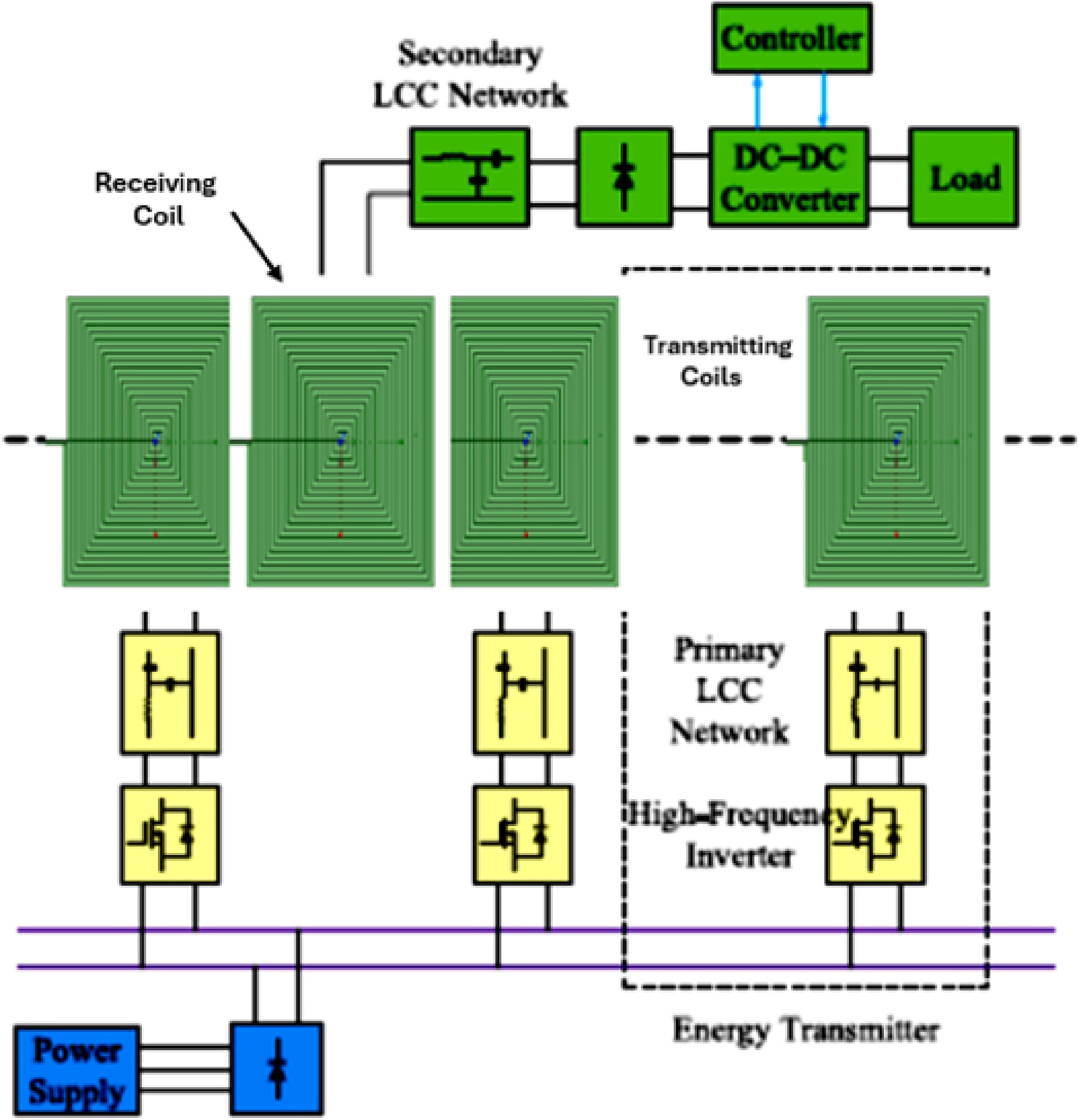
Figure 1.
Schematic diagram of the DWPT system.
The efficiency and cost-performance of the DWPT are highly dependent on the type and configuration of the coils used. Several designs have been developed to optimize coupling, minimize energy losses, and ensure constant, smooth energy transfer during vehicle movement. Various configurations have been identified, such as circular, rectangular, segmented, and dual function (DDQ) coils, each offering advantages in terms of efficiency, range, and robustness against misalignment[20−24].
Circular coils are simple to produce and offer good performance over short distances. But the problem lies in their sensitivity to alignment problems, as demonstrated by the Stanford University project[25]. In the field of DWPT technology, circular coils are used in a number of innovative projects to recharge electric vehicles wirelessly. In Seoul (South Korea), for example, recharging systems for electric buses have been installed with circular coils integrated under the rails, enabling the buses to be recharged continuously as they travel, reducing the need for recharging stops. In Sweden, the 'ELECTRIcity' project is experimenting with roads equipped with these coils, transforming road infrastructure into dynamic recharging systems for vehicles[26]. These projects demonstrate the ability of DWPT circular coils to transform the charging system for electric vehicles, making it more convenient and easily accessible.
Rectangular coils improve magnetic coupling over longer distances, reducing the effect of vehicle misalignment. Several projects have integrated rectangular coils into DWPT systems to improve energy transfer to electric vehicles on the move. Developed by KAIST, the OLEV project in South Korea has integrated these coils into the roadway to ensure recharging of electric buses, thus improving magnetic coupling. In Europe, the FABRIC project, funded by the European Union, explored the feasibility of DWPT on freeways, reducing the impact of vehicle misalignment. In Germany, Conductix-Wampfler's IPT project experimented with these coils as an energy source for electric streetcars and buses not equipped with bulky batteries. Finally, with tests carried out in Sweden, Germany, and France, these kinds of coils improve magnetic coupling and reduce the effects of misalignment[27−29].
Segmented coils, which are divided into independent segments, offer better management of energy distribution according to vehicle positioning. This optimizes energy efficiency and minimizes losses[30,31]. By activating only the essential segments according to the vehicle's path, this technology guarantees continuous, high-performance recharging, even if the vehicle is in movement. This technology is used in various projects, such as the Sustainable Urban Mobility (SUM) initiative in Sweden. This project is experimenting with the integration of DWPT systems using segmented coils to make public transport and electric vehicles more accessible and sustainable.
This study makes several significant contributions to the literature on DWPT systems. It provides an in-depth analysis of the behavior of the coupling coefficient in rectangular coil configurations, taking into account real-world operating conditions. The work highlights the advantages of rectangular geometry, which is simple to implement, and well-suited for practical applications. The study is conducted by considering the different distance classes defined by the SAE J2954 standard. Furthermore, the impact of receiver coil misalignment under dynamic conditions is analyzed, demonstrating its direct influence on power transfer. Finally, the use of the finite element method enables accurate modeling of the electromagnetic behavior for the spacing between different transmitter coils to ensure continuous energy transfer during the movement of the electric vehicle along the dedicated electric road for the DWPT system.
This state-of-the-art paper explores the different types of coils used in DWPT systems, their operating principles, and the technological challenges associated with their implementation in dynamic recharging infrastructures.
-
A rectangular coil is a type of coil whose design is characterized by a rectangular coil winding. It is frequently used in applications where a uniform magnetic field is desired, or to minimize induction losses[32]. Analysis of this coil involves determining its inductance, power, and magnetic field from the coil's geometric and electrical parameters. Here are the main equations and concepts involved.
Compared with existing coil topologies such as circular and double-D (DD) structures, the proposed rectangular coil introduces several unique advantages. First, the rectangular geometry (360 mm × 360 mm), illustrated in Fig. 2, allows a more efficient utilization of the available surface area, whereas circular and DD coils generally leave unused gaps that reduce the effective flux-carrying region. This improved spatial efficiency directly contributes to stronger mutual coupling and reduced leakage flux. This enhancement is obtained with a simplified design, without the need for complex multilayer arrangements. Third, due to its uniform turn distribution, the rectangular coil ensures a more homogeneous magnetic field in the central region, which improves tolerance to lateral misalignments, a critical requirement for DWPT applications.
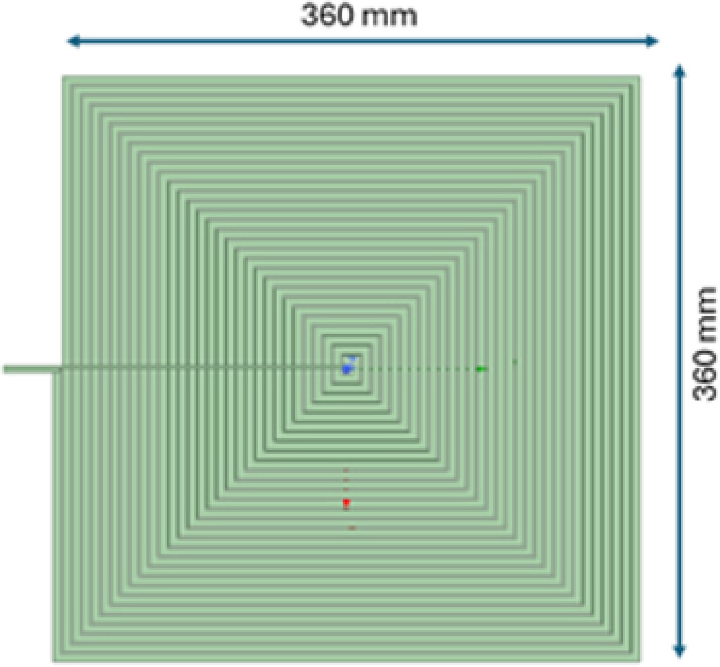
Figure 2.
Conception of a rectangular coil modeled using software.
An additional novelty of this work is the consideration of cost-effective optimization. The proposed design minimizes the required length of Litz wire, which represents a significant portion of the system cost, especially in large-scale DWPT infrastructures. At the same time, the coil's inductance can be further enhanced by strategically placing ferrite plates beneath the windings, rather than increasing the winding length. This trade-off not only reduces conductor losses and material costs but also maximizes the coil's electromagnetic performance.
Therefore, the novelty of this work lies in the optimization and validation of a rectangular coil geometry specifically tailored for DWPT, highlighting its potential to achieve higher inductance, improved coupling efficiency, better misalignment robustness, and cost-effective implementation compared with conventional circular and DD coils.
Rectangular coil inductance
-
The calculation of the inductance of a rectangular coil depends on several key parameters, which must be optimized to increase the inductance value and enable high power transfer. These parameters include the number of turns and the cross-sectional area of the coil. In general, increasing the number of turns increases the total length of the Litz wire, which results in higher inductance. However, in a wireless power transfer application for electric vehicles, the receiving coil must be integrated under the vehicle, which imposes significant space constraints. It is therefore necessary to minimize the dimensions of the coil while ensuring high power transfer. This issue leads to a compromise between the size of the coil, the inductance obtained, and the overall performance of the energy transfer system.
In this section, we present the calculation of the inductance of the two coils, whose dimensions are shown in Fig. 2: Tx1, corresponding to the transmitter coil, and Rx, corresponding to the receiver coil. First, the inductance of each coil is calculated individually, without any additional magnetic material. Next, a ferrite plate is integrated into the model, as shown in Fig. 3, to analyze its influence on the inductance value and improve magnetic flux confinement.
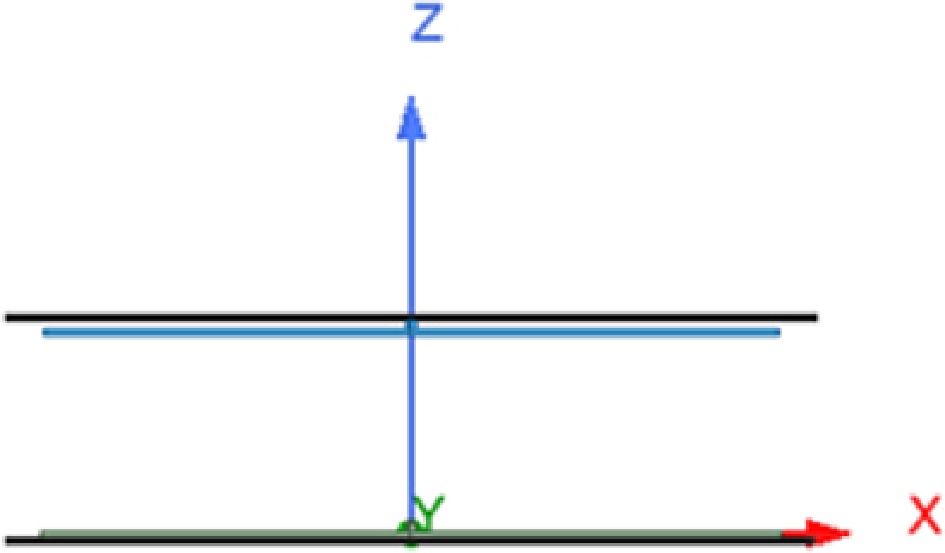
Figure 3.
Transmitting and receiving coil with ferrite.
The inductance values reported in Table 1 are obtained through numerical simulations using ANSYS Maxwell based on the finite element method (FEM). The simulations are carried out under perfect alignment conditions between the transmitter and receiver coils. The vertical air gap is fixed at z = 125 mm, which corresponds to an average value within the recommended range defined by the SAE J2954 standard (Z1 class: 100–150 mm).
Table 1. Inductance of the rectangular coils.
Gap (mm) Without ferrite With ferrite L(µH) Tx1 M(µH) Tx1/Rx L(µH) Tx1 M(µH) Tx1/Rx 100 136 39 244 95 120 135 31 237 74 We observe that the inductance value depends on the spacing between the receiving coil and the transmitting coil, and that adding a ferrite plate can increase the value while keeping the same coil size. For this reason, in the following and for the prototype part at the laboratory level, we have a fixed part for the integration of the receiving coil. We propose adding ferrite because of its low price compared to litz wire.
Inductive coupling
-
The coupling factor K between the two coils (transmitting and receiving) is critical in transferring the maximum amount of energy from the transmitting coil to the receiving coil[33]. To increase the efficiency of the DWPT charging system, it can be approximated as follows:
$ \mathrm{K}=\dfrac{\mathrm{M}}{\sqrt{\mathrm{L}1\cdot\mathrm{L}2}} $ (1) where, M is the mutual inductance between the coils, and L1 and L2 are the respective inductances of the transmitting and receiving coils.
It is important to emphasize that mutual inductance M may be positive or negative depending on the adopted dot convention and the reference orientation of the windings. The negative value of M does not indicate the absence of magnetic coupling; rather, it corresponds to opposite flux linkage under a defined reference direction. To avoid ambiguity, the present manuscript refers to this phenomenon as a sign inversion of mutual inductance rather than negative magnetic coupling.
Resonance frequency
-
Resonant frequency is a key factor in the efficient operation of DWPT systems, influencing energy transfer efficiency, magnetic coupling, loss reduction, and system stability[34]. The system's resonant frequency is given by:
$ \mathrm{f}=\dfrac{1}{2\text{π} \sqrt{\mathrm{L}\cdot\mathrm{C}}} $ (2) where, L is the coil inductance; C is the resonance circuit compensation capacitance.
For the DWPT system, the interval range recommended by SAEJ2954 (81−91 kHz). The equation is used to calculate the compensation capacitors as a function of the transmitting and receiving inductances.
The coupling coefficient K is fundamentally a geometric parameter and does not directly depend on operating frequency. For a fixed coil position and magnetic configuration, k remains constant.
However, in resonant inductive power transfer systems, the electrical influence of coupling depends on frequency through the mutual reactance:
$ {X}_{M}=\omega M $ (3) where, ω = 2πf is the angular frequency.
Thus, while the geometric coupling remains unchanged, the voltage and current interactions between coils vary with frequency due to impedance transformation and resonance conditions. This explains why system performance metrics such as power transfer efficiency (PTE), transferred power, and stability exhibit frequency dependence, even though the geometric coupling coefficient itself does not.
Power in the rectangular coil
-
The power transferred between coils is often described by the expression:
$ {P}_{max}={S}_{tx}{S}_{rx}M{w}_{r}J_{1}^{2}\sqrt{{q}_{v}} $ (4) where, M is the mutual inductance between the coils. Stx primary coil section. wr is the angular frequency (wr = 2π·f). Jtx primary current densitie. qv coil volume ratio (
$ {q}_{v}=\dfrac{{V}_{tx}}{{V}_{rx}} $ It has been observed that, to maximize the power transferred, several parameters can be adjusted as long as the coil cross-section remains fixed. Due to the dimensional constraints imposed by the laboratory protocol, the dimensions chosen were defined to ensure the transfer of 5 kW of power. The system is based on coils with a cross-section of 360 mm2, made of 5 mm diameter Litz wire, with 30 turns on both the transmitter and receiver sides. The primary DC bus is set at a voltage of 400 V.
Based on the relationships established above, it appears that the transfer of maximum power in a WPT system depends mainly on obtaining a high coupling coefficient k and choosing a suitable excitation frequency. Since k depends directly on mutual inductance M, which increases with the number of turns, the effective surface area of the coil, and the quality of the conductor, geometric optimization of the winding is an essential lever for improving system performance.
However, the use of conductors suitable for high frequencies, particularly Litz wire, involves a high cost as well as an increase in the mass of the windings. To reconcile these constraints with electromagnetic requirements, we have chosen an optimized coil geometry that minimizes the total length of the wire while maintaining the required inductance. This configuration makes the receiver coil lighter and increases the overall efficiency of energy transfer.
The chosen design is therefore a relevant technical compromise between maximizing mutual inductance, reducing losses, controlling costs, and mechanical constraints, making it a suitable solution for DWPT applications requiring high efficiency.
-
In this section, we focus on analyzing rectangular magnetically coupled main coils, which measure 360 mm × 360 mm (Fig. 2), by associating them with a 400 mm × 400 mm ferrite plate. Each coil consists of 30 turns. To explore the effect of electromagnetic coupling, we vary the distance along the z-axis between the transmitting and receiving coils, which we refer to as the 'gap'. In addition, to simulate the misalignment of an electric vehicle moving over the transmitting coils, we also adjust the distance along the x axis to a fixed gap, which we call 'dist_x'. The objective of this approach is to better understand how these variations influence magnetic coupling.
The distribution of magnetic flux density
-
In this section, we focus on analyzing rectangular magnetically coupled main coils, which measure 360 mm × 360 mm (Fig. 2), by associating them with a 400 mm × 400 mm ferrite plate. Each coil consists of 30 turns. To explore the effect of electromagnetic coupling, we vary the distance along the z-axis between the transmitting and receiving coils, which we refer to as the 'gap'. In addition, to simulate the misalignment of an electric vehicle moving over the transmitting coils, we also adjust the distance along the x axis to a fixed gap, which we call 'dist_x'. The objective of this approach is to better understand how these variations influence magnetic coupling.
The geometry has just rectangular coils and ferrite core without additional shielding (e.g., aluminum plates) to study the fundamental field distribution and coupling behavior. However, in real-world integration into electric vehicles, shielding using aluminum is unavoidable for snubbing stray fields and enhancing system safety and electromagnetic compatibility (EMC).
The coils are powered by a 5A sinusoidal AC current at an operational frequency of 85 kHz, as required by the SAE J2954 standard for dynamic wireless charging. The gap between the receiver coil and the transmitter plane is established at 150 mm, the typical clearance in EV applications.
We placed an xy-direction sheet between the primary and secondary coils to visualize the magnetic flux distribution. As shown in Fig. 4, we notice that the magnetic field density is particularly strong in the center of the foil. This is particularly important in the case of small misalignments along the y axis. Indeed, if the alignment is not perfect, this phenomenon becomes crucial, especially in dynamic situations where the receiver coil is in motion.
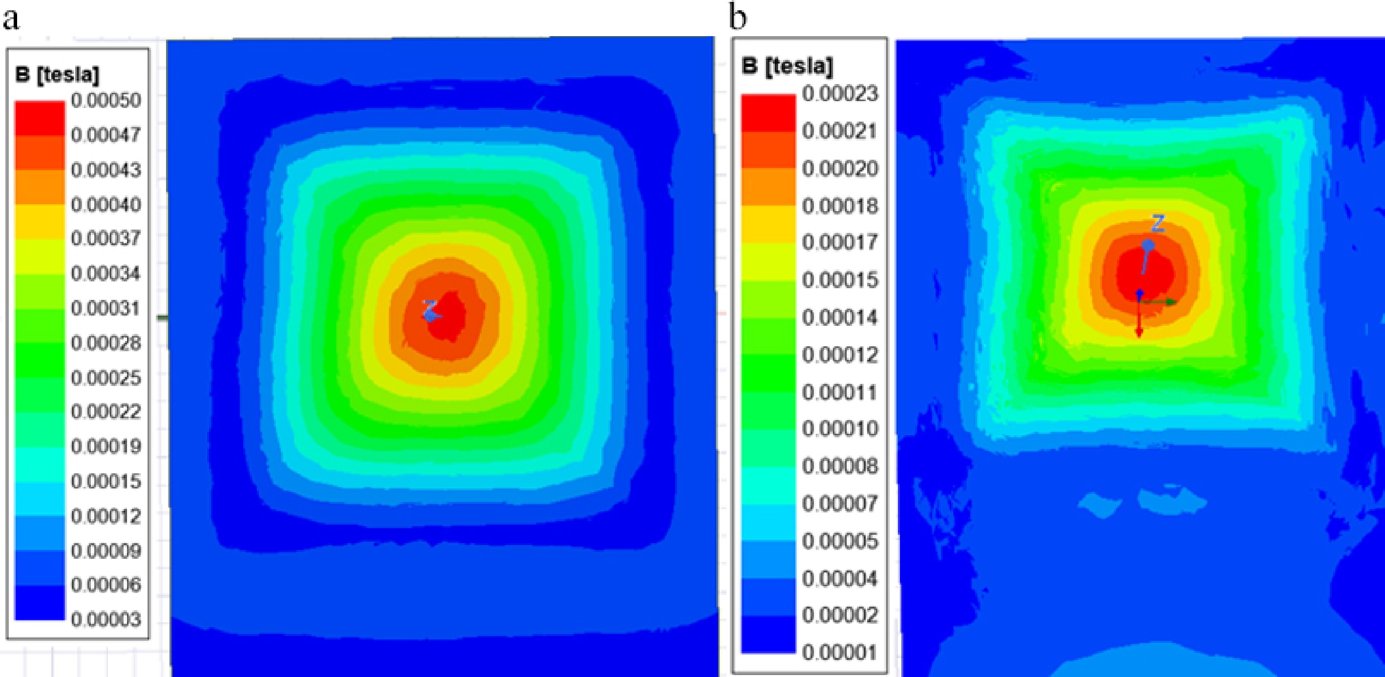
Figure 4.
The magnetic field distribution on the YZ plane was simulated under the same conditions: (a) with ferrite, (b) without ferrite.
Effect of gap and ferrite plate
-
In this section, we will look at the impact of gap distance, as different electric vehicles require different gaps depending on their size. According to the SAE J2954 standard[35], three gap classes (see Fig. 5) are defined: z1 = 100−150 mm, z2 = 140−210 mm, z3 = 170−250 mm.
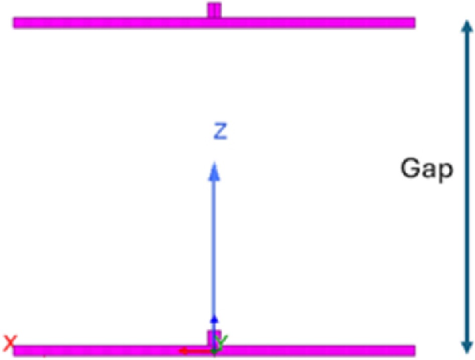
Figure 5.
Distance between the transmitter and receiver coil along the z axis.
We analyze the results obtained from FEM simulations. Figure 6 shows the coupling coefficient between the transmitting coil and the receiving coil as a function of variation in the gap distance.
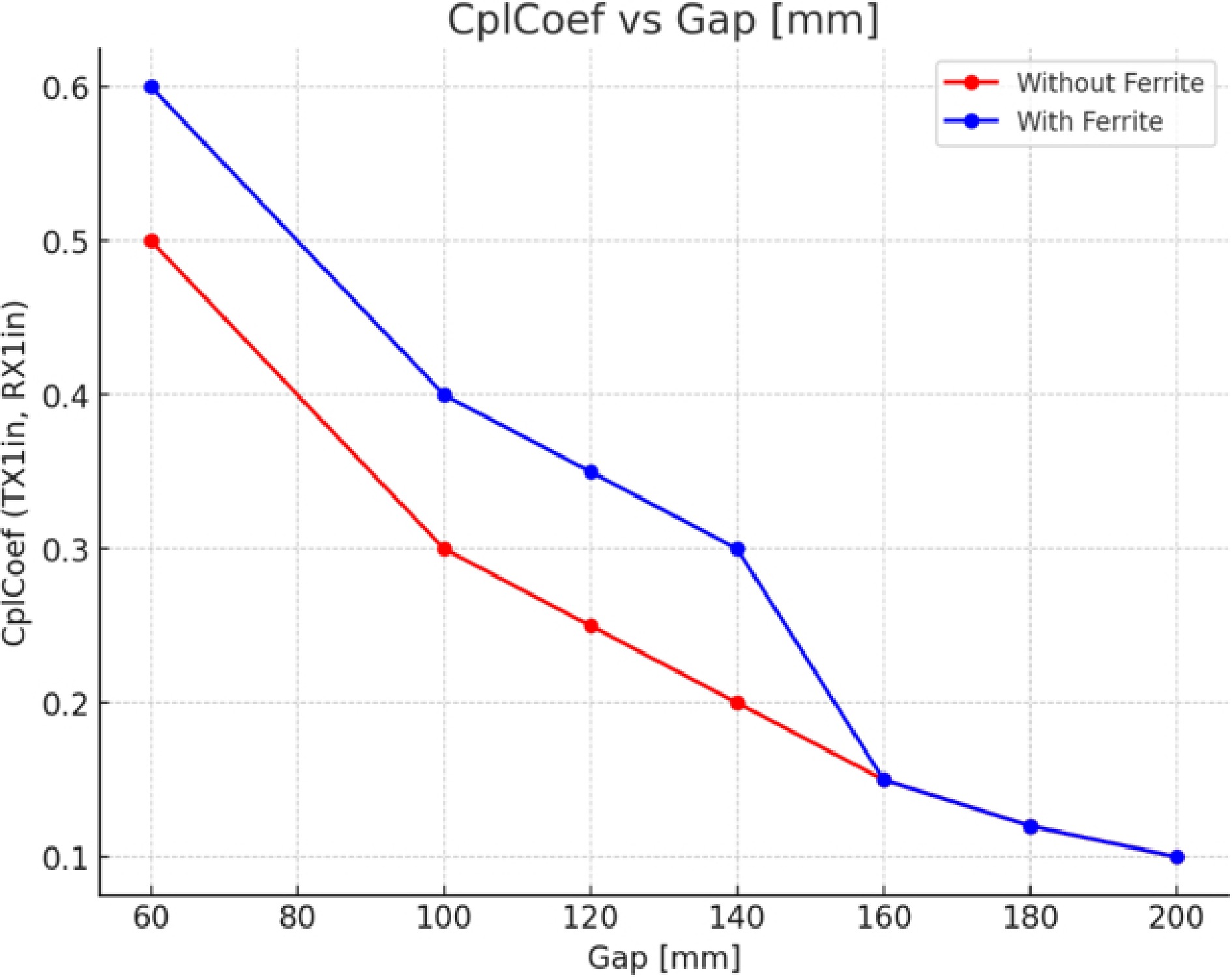
Figure 6.
Coupling factor for different gap values.
In both scenarios, with and without ferrite, Fig. 6 shows that the coupling coefficient decreases as the gap increases. However, this effect is more pronounced in the absence of ferrite. This indicates that ferrite cores play an essential role in maintaining good coupling. Furthermore, it highlights the importance of reducing the gap in wireless energy transfer systems, to ensure more efficient energy transfer.
The introduction of ferrite into the coupling zone significantly alters the coupling value between the two coils in simulation. Thanks to its high permeability, the material concentrates and channels the flux into a preferred magnetic path, which can reinforce the mutual component of the field depending on its position relative to the coils. The results show that adding ferrite increases the coupling coefficient, even when the coils are partially misaligned. This improvement in coupling offers an interesting design avenue: it becomes possible to reduce the amount of Litz wire, which is particularly expensive while maintaining a satisfactory level of coupling by optimizing the ferrite structure.
From an analytical point of view, the effect of ferrite on the coupling coefficient is intrinsically limited to the near-field region. The mutual inductance between the transmit and receive coils is proportional to the mutual magnetic flux, which follows a dipole-type decay with distance. At short Tx-Rx distances, ferritic materials increase the effective permeability and guide the magnetic flux, resulting in improved mutual inductance and coupling coefficient. As the separation distance increases, the magnetic field strength decreases rapidly, and the flux guiding ability of the ferrite becomes negligible compared to the field distribution in free space. Therefore, beyond a certain distance, the coupling coefficient converges to the same values obtained without ferrite.
Effect of coil misalignment
-
In this section, we'll simulate misalignment, which corresponds to the situation where the vehicle moves along the x-axis while the reference frame is slightly rotated or offset, Fig. 7 represents this misalignment. We set a gap deviation of 100 and designate 'dist_x' as the center position of the receiver coil. When dist_x is zero, this means that the transmitting and receiving coils are perfectly aligned. Using the FEM method, we move the receiver coil in the direction of movement, to calculate the coupling coefficient for different values of dist_x.
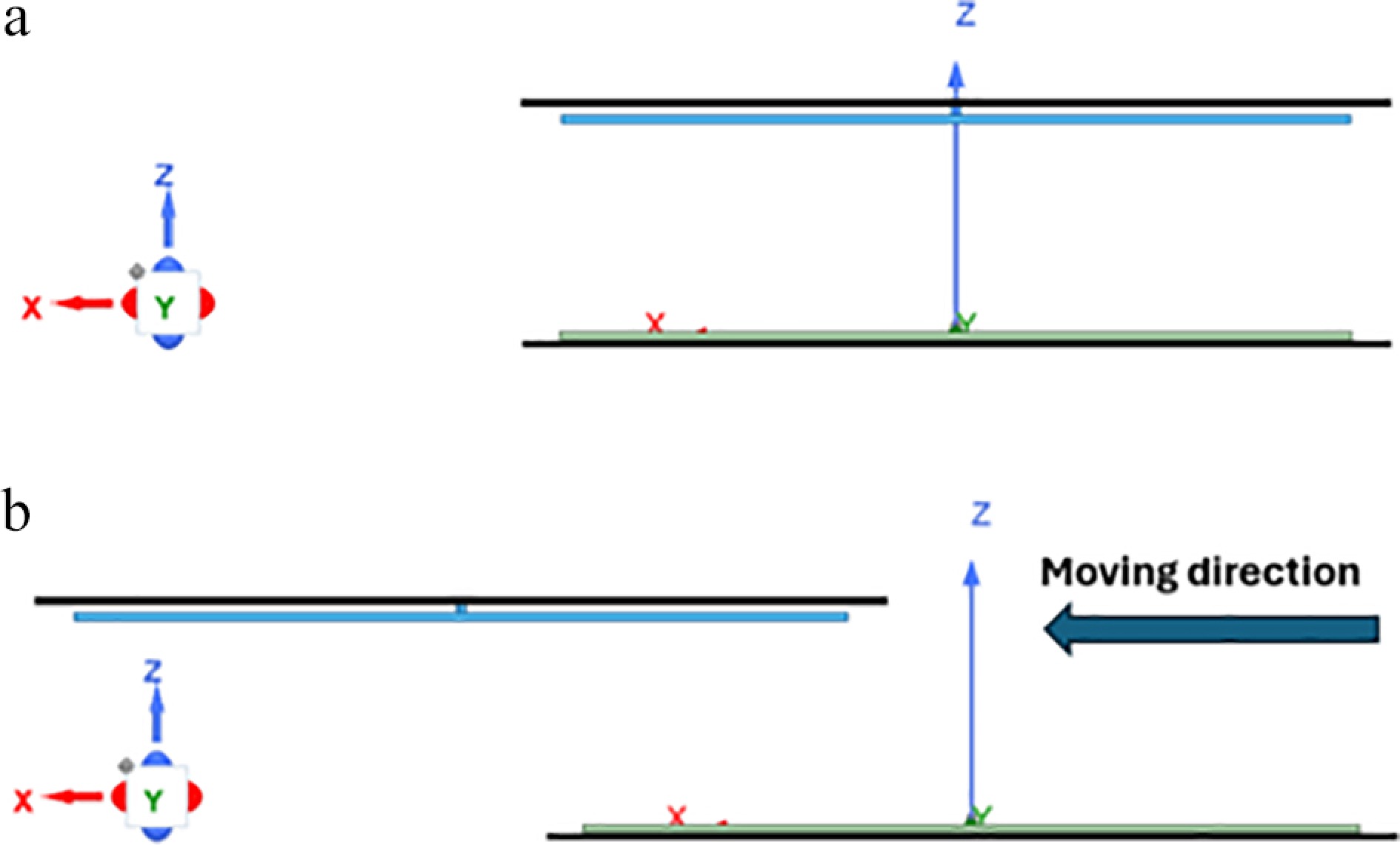
Figure 7.
Misalignment of receiver coil: (a) dist_x = 0, (b) dist_x = 240 mm.
Figure 8 shows that the coupling coefficient K gradually decreases as the receiver coil moves. Above a critical distance of around 240 mm, the coupling coefficient stabilizes at a value close to zero, indicating that coupling becomes virtually ineffective. This means that when the receiving coil moves completely outside the transmitting coil's zone of influence, the coupling coefficient can even become negative. To solve this problem, additional transmitting coils are added, enabling a positive coupling coefficient to be maintained.
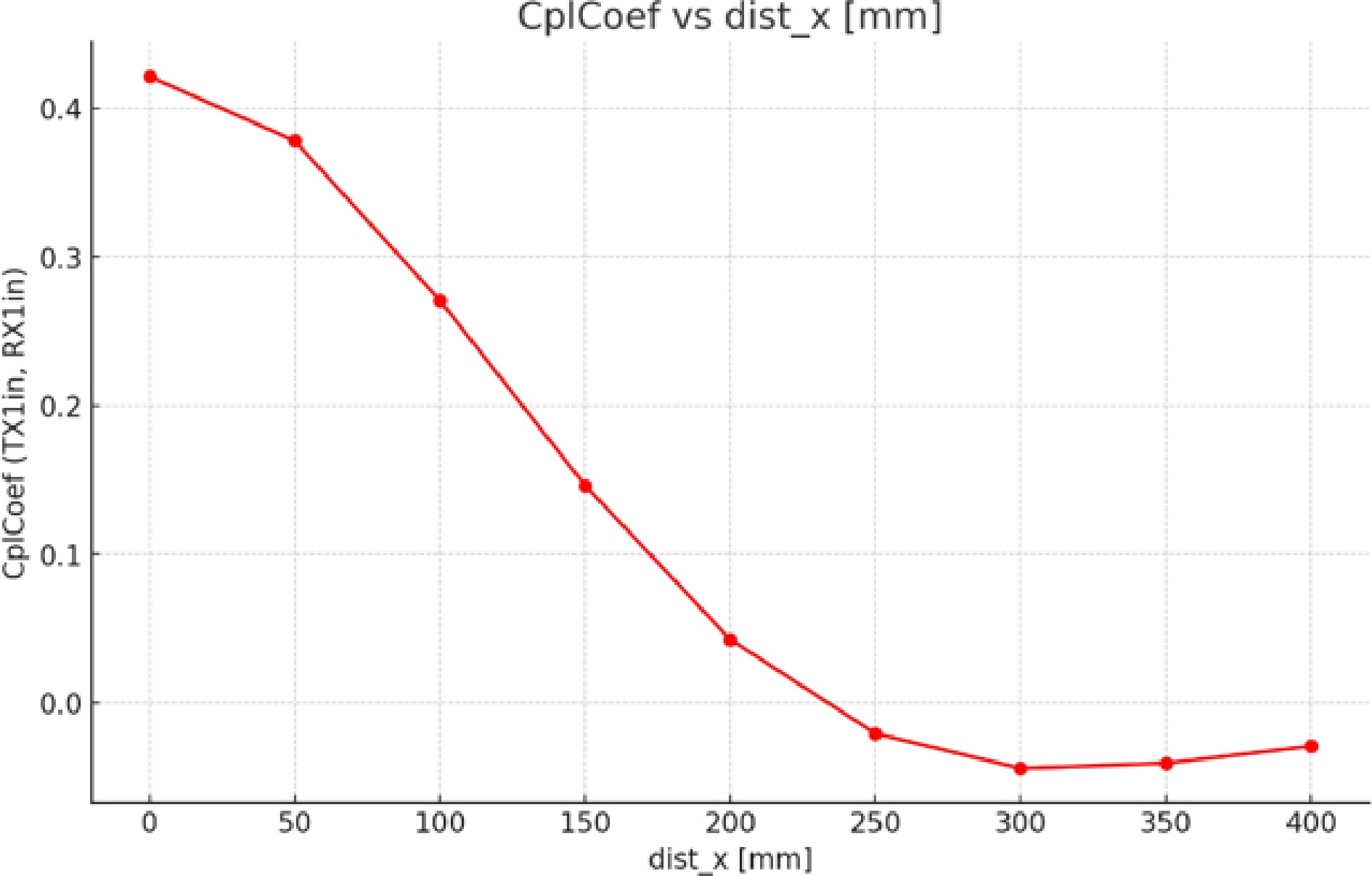
Figure 8.
Coupling factor for different dist_x values.
Case of DWPT
-
In this section, we analyze the behavior of rectangular coils in a system with several segmented transmitter coils. The aim is to maintain a high coupling coefficient while an electric vehicle is in motion. Figure 9 illustrates the circuit topology of a DWPT charger, which forms the basic system required for wireless energy transfer when charging a moving electric vehicle.
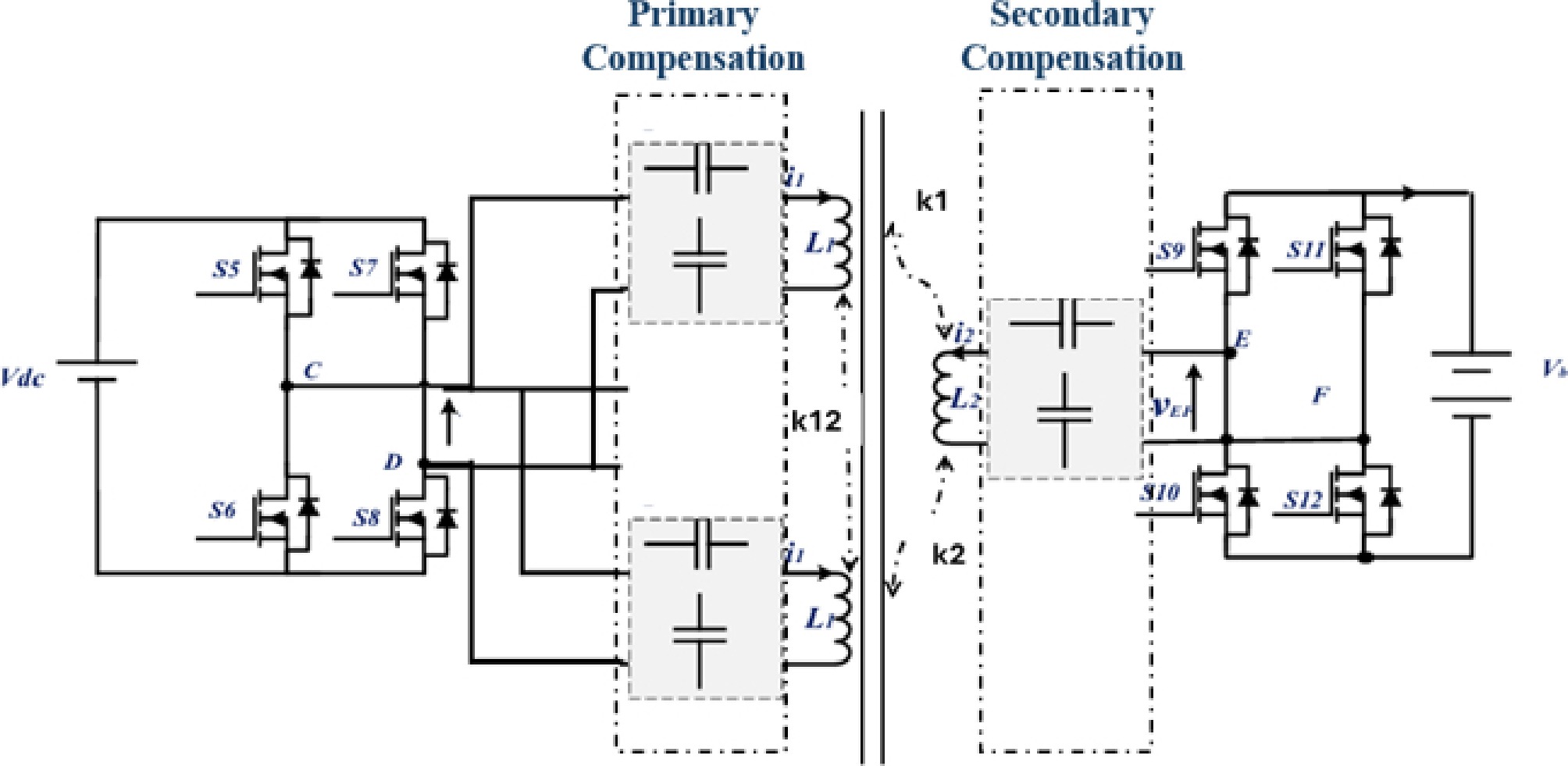
Figure 9.
circuit topology of a DWPT.
The circuit comprises:
A high-frequency inverter (approx. 85 kHz) to minimize switching losses, transmitting coils associated with compensation capacitors, and switches to activate each transmitter coil according to the actual position of the receiver coil, to improve the overall efficiency of the DWPT system.
On the electric vehicle side, a receiver coil is integrated into the chassis, together with its compensation circuit. Finally, a rectifier converts the voltage from the secondary compensation to match the needs of the electric vehicle's battery.
In the case of several transmitting coils and one receiving coil moving along the direction of motion, we identify three important coupling coefficients between the coils: Ki: the coupling coefficient between the TXi transmitting coil and the RX receiving coil. Kj: the coupling coefficient between the TXj transmitting coil and the RX receiving coil. Kij: the coupling coefficient between two transmitting coils TXi and TXj (where i ≠ j).
These coefficients are essential for assessing the efficiency of energy transfer between coils. Indeed, a high coupling coefficient indicates better magnetic interaction between the coils, which is crucial for optimizing the wireless energy transfer system, especially when the receiving coil is in motion.
The K coefficient is key to energy transfer efficiency: the higher the coefficient, the greater the power transferred. This coefficient depends on the distance between the coils, their alignment, and the frequency of the electromagnetic wave. According to the previous research by Bouanou et al.[36], and the power transfer Eq. (3), the operating frequency plays a crucial role in maximizing the transferred power. However, increasing the frequency introduces a trade-off, as higher frequencies lead to increased control and switching-related Joule losses in the power electronics stage.
Using the FEM method, Fig. 10 illustrates the configuration used to analyze misalignment when the vehicle moves along the x-axis. Two transmit coils, labeled TX1 and TX2, are positioned longitudinally in the direction of movement. The receiving coil RX is placed above the plane, with a three-dimensional reference frame indicating the x, y, and z-axes. The movement of the vehicle, represented by a black arrow pointing to the right occurs mainly along the x-axis.
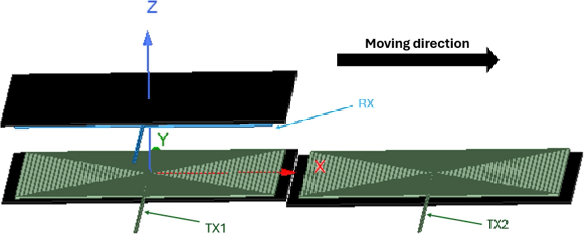
Figure 10.
Segmentation of transmitter coils.
The results of the simulation are illustrated in Fig. 11, showing the evolution of the coupling coefficient as a function of the direction of movement of the receiver coil. This representation makes it possible to analyze how coupling varies as the receiver coil moves along its axis, which is essential for optimizing energy transfer in wireless charging systems.
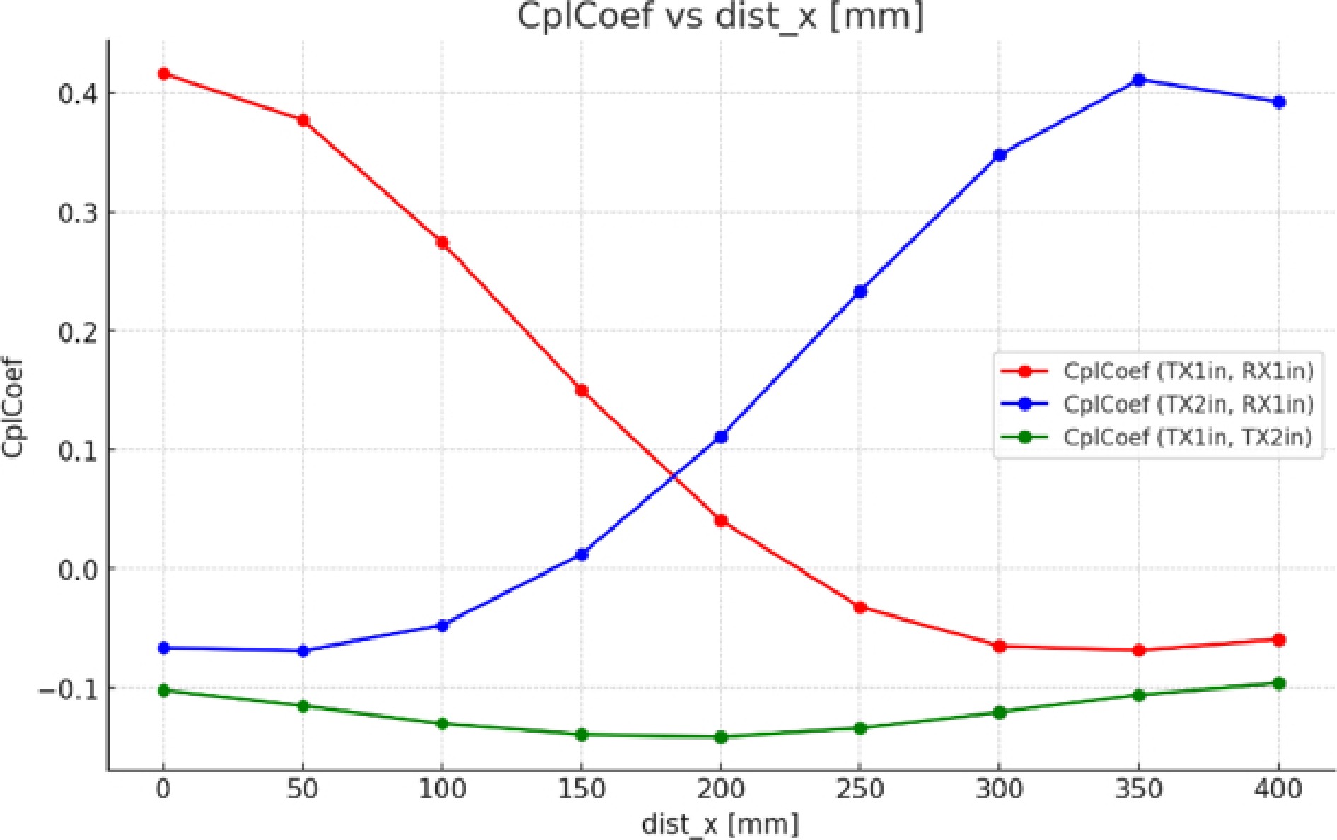
Figure 11.
Coupling factors for different coils.
According to Fig. 11, the behavior of the coupling coefficients between the transmitting coils and the receiving coil changes as a function of the latter's position:
(1) Decrease in K1: The coupling coefficient K1, representing the coupling between the first transmitting coil (Tx1) and the receiving coil (RX), decreases progressively as the receiving coil moves further away from Tx1.
(2) Increase in K2: In contrast, the coupling coefficient K2, between the second transmitting coil (Tx2) and the receiving coil, increases as RX moves closer to Tx2.
Transitions between transmitting coils
-
To optimize energy transfer efficiency and avoid unnecessary losses:
(1) Simultaneous activation: When K1 and K2 are equal, both transmitting coils (Tx1 and Tx2) operate together to ensure a smooth transition.
(2) Tx1 deactivation: Once the receiver coil moves further away from Tx1, the latter is deactivated.
(3) Activate Tx2: Tx2 then takes over to continue feeding the receiver coil.
This process is repeated throughout the electric vehicle's journey, reducing unnecessary energy consumption while maintaining efficient energy transfer.
The green curve, representing the coupling coefficient Kij between the two adjacent transmitting coils (Tx1 and Tx2), shows a negative value. This has a direct impact on the overall coefficient K, which is the sum of coefficients Ki, Kj, and Kij.
Effect of a negative coefficient: When Kij is negative, it acts as a component that reduces the total value of K. This means that the magnetic interaction between Tx1 and Tx2, instead of enhancing energy transfer, creates an opposition that decreases the overall efficiency of the system.
The overall coefficient K is defined as the sum of the three coefficients: K = Ki + Kj + Kij. When Kij is negative, it acts as a component that reduces the total value of K, thus decreasing the efficiency of energy transfer. Making Kij negligible simplifies the equation to: K ≈ Ki + Kj, which reflects only the direct contributions of the Tx1 and Tx2 transmitting coils to the RX receiving coil.
The simulation results enable precise analysis of the evolution of the magnetic coupling between the two coils and the influence of the ferrite material on the flux distribution. Initial observations show that, depending on the geometric configuration of the windings, the flux generated by the receiving coil can pass through the transmitting coil in a direction opposite to that of its own flux. This reversal leads to the appearance of negative mutual inductance, reflecting a local opposition between the fields produced by the two coils. This behavior is confirmed by analysis of the resulting field: when the receiving coil moves and half of its surface leaves the coverage area of the transmitting coil, the amplitude of the mutual field gradually decreases until it reaches a negative value, consistent with the reversed orientation of the resulting flux in this configuration.
In the area where the coupling coefficient decreases, a reduction in power may be observed, as indicated in previous studies[37,38]. To remedy this problem, these studies propose the use of a repeater based on a controllable frequency shift method, which allows constant output power to be maintained during movement.
For the same problem, we have adopted a different approach based on nonlinear control, which ensures constant power even at high speeds[39].
Segmentation of transmitter coils
Among the methods for neglecting Kij
-
Increase the distance between Tx1 and Tx2: The coupling coefficient between two coils decreases rapidly with increasing distance. By spacing Tx1 and Tx2 sufficiently far apart, Kij can be reduced to a value close to zero.
Use magnetic materials: The addition of magnetic materials (such as ferrites) around coils can concentrate magnetic fluxes and limit interactions between Tx1 and Tx2, thereby reducing Kij.
In this section, we introduce a new parameter, XX illustrate in Fig. 12, which represents the distance between two adjacent transmitter coils. By varying this distance and moving the receiver coil, we aim to achieve an optimum coupling coefficient as the vehicle moves over the transmitter coils. We retain the same coil parameters used in previous sections.
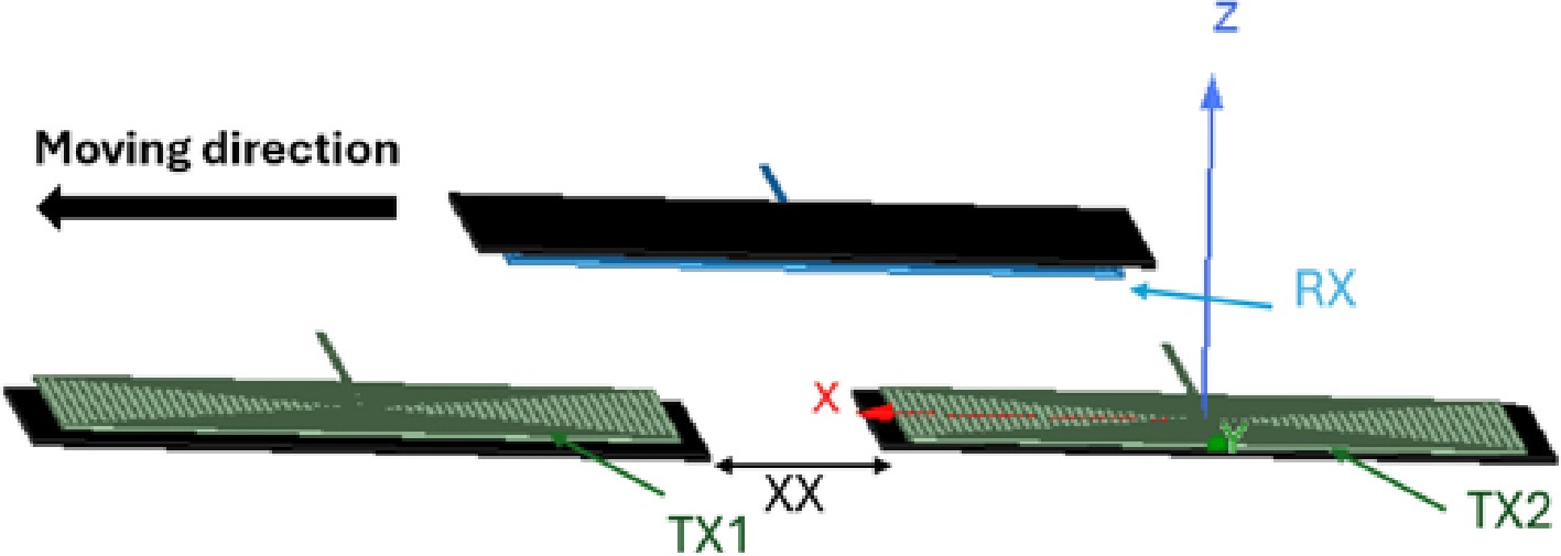
Figure 12.
Segmentation of transmitter coils with different XX values.
Segmentation of the transmitting coils also helps to reduce losses due to inductive coupling by maintaining an optimum distance between the transmitting coils and the vehicle receivers. This improves the efficiency of wireless energy transfer, which is essential for dynamic recharging systems for electric vehicles.
Using the FEM, an in-depth analysis of the coupling coefficients between the various coils was carried out. Figure 13 illustrates the behavior of the coupling coefficient between transmitter coil Tx1 and receiver coil RX as a function of different values of XX (distance between two adjacent transmitter coils), while moving the receiver coil along the trajectory of the electric vehicle (dist_x).
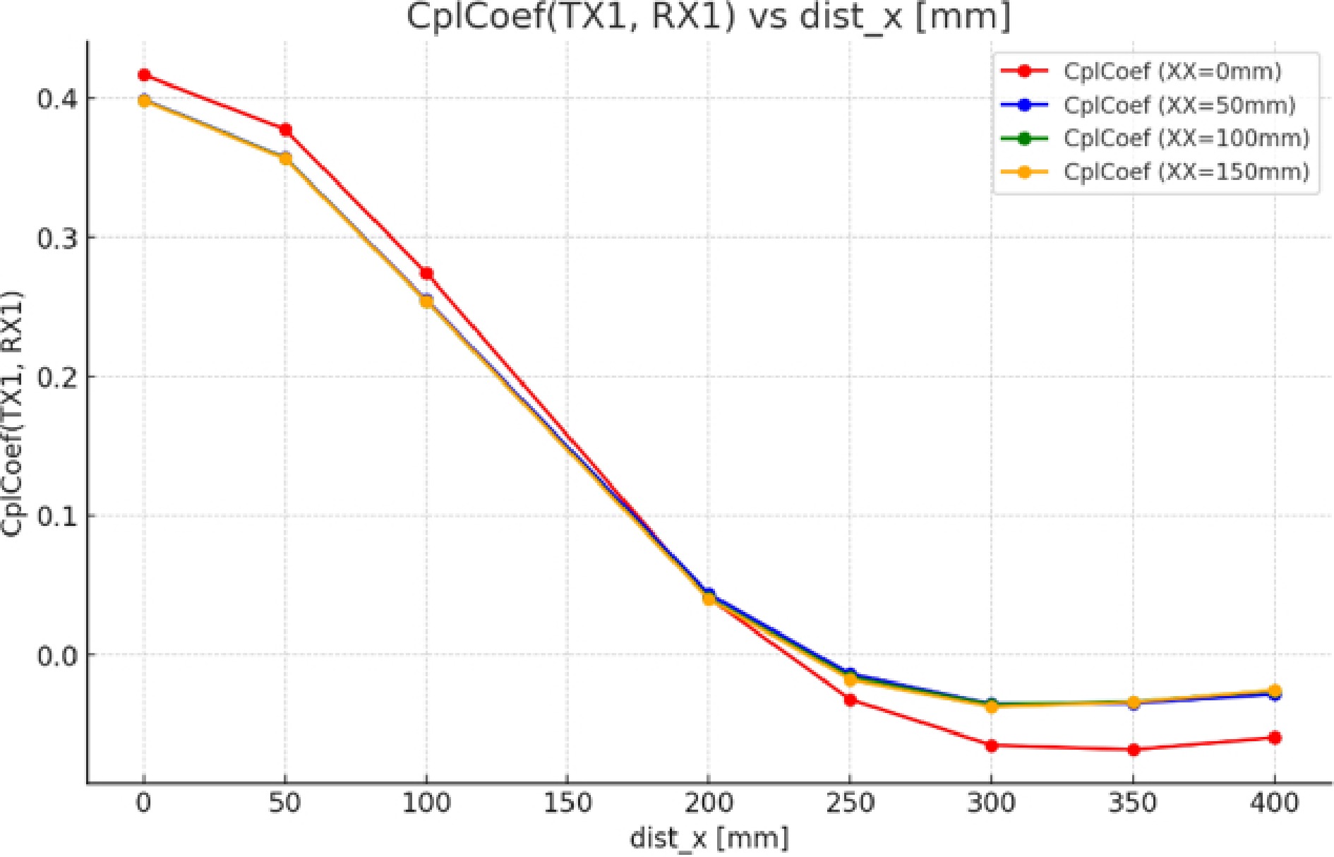
Figure 13.
Coupling factor between TX1/RX for different values of XX.
Figure 14 shows the coupling coefficients as a function of different values of XX. Whenever the two transmitting coils are far apart, the coupling coefficients shift with distance XX in the interval [200, 400], where the receiving coil is close to the second transmitting coil. For example, for XX = 0 and dist_x = 200 mm, the coupling coefficient is close to 0.1. A similar value is obtained for XX = 50, XX = 100, and XX = 150 mm, with dist_x values equal to 250, 300, and 350 mm, respectively.
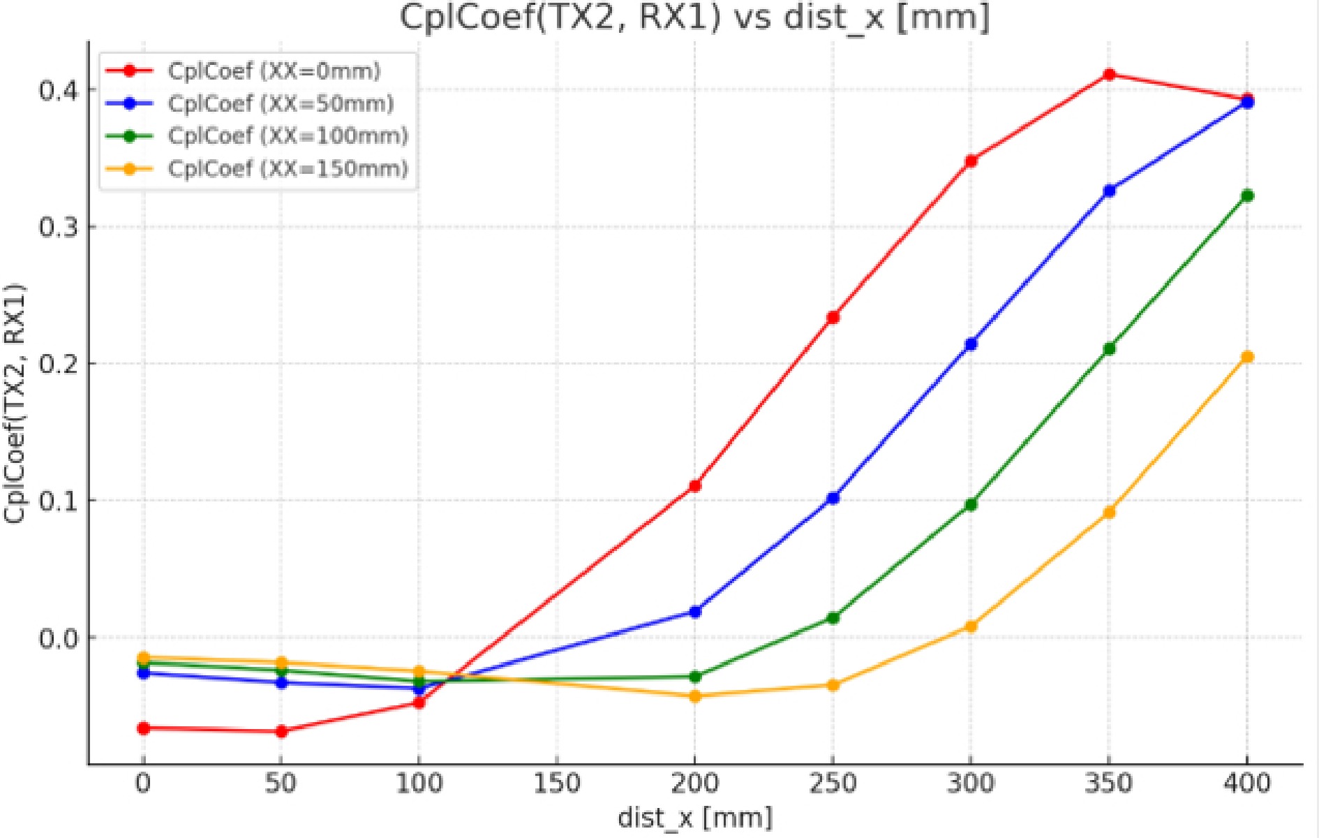
Figure 14.
Coupling factor between TX2/RX for different values of XX.
Figure 15 shows the coupling coefficient between two adjacent transmitting coils by changing the distance between the two coils and moving the receiving coil.
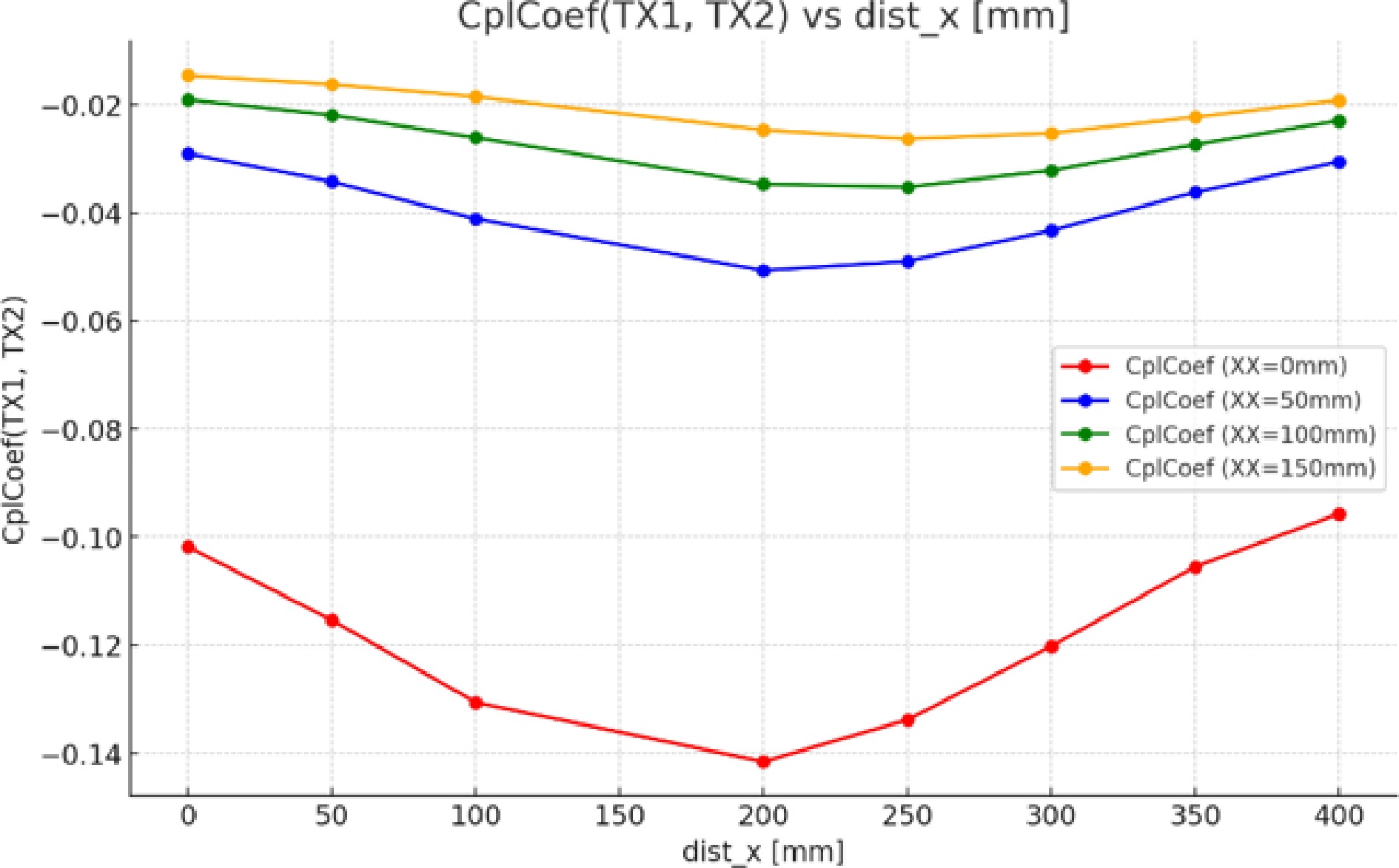
Figure 15.
Coupling factor between TX1/TX2 for different values of XX.
At other values of XX (50, 100, and 150 mm), the coupling coefficient is higher than for XX = 0 mm, but the evolution remains similar: as dist_x increases, the coefficient stabilizes at lower values.
As distance XX increases, the coupling coefficient increases with each value of dist_x, with a marked difference for XX = 150 mm. The curves also show that increasing dist_x leads to a stabilization or slight decrease in the coupling coefficient.
Although the current study concentrates on modeling the process of mutual inductance variation due to receiver-coil displacement, experimental confirmation is certainly needed. The mutual inductance model developed herein will be included within a complete DWPT system and utilized within nonlinear control approaches, which are aimed at compensating for the lost coupling when the receiver is positioned between two adjacent transmitters. We have contemplated an experimental campaign, comprising the realization of a multi-coil DWPT test bench, the measurement of mutual inductance with respect to different displacement conditions, and the comparison of these measurements against simulation outcomes described herein.
-
The results obtained confirm and extend the hypotheses reported in the literature concerning the high sensitivity of DWPT systems to fluctuations in magnetic coupling, particularly those caused by misalignments and dynamic operating conditions. Furthermore, this study represents a methodological advance by laying the foundations for more realistic modeling of DWPT systems. The integration of coupling coefficient variation into the mathematical model reduces the gap between theoretical analyses and practical implementations, while providing a more suitable framework for the development of robust control laws for dynamic environments[39].
In addition to control-oriented improvements, recent research also underlines the importance of architectural simplification and material optimization in WPT systems. The use of second-harmonic operation with single-switch drivers reduces the number of required inverters and simplifies the overall electronic architecture. Optimized coil geometries, such as Rectangular, DD, or RDSP structures, together with magnetic integration techniques, contribute to lowering the amount of copper and ferrite required, thereby reducing system weight and cost. Moreover, so-called control-free approaches eliminate the need for complex sensing and active control circuits, significantly decreasing system size and implementation expenses. Dual-resonant-frequency converters have been shown to increase transferred power while minimizing component stress and physical footprint. These trends collectively highlight a parallel evolution in DWPT systems toward both higher robustness and greater structural efficiency[40,41].
The overall significance of this work lies in its potential contribution to the design of more reliable and efficient DWPT systems, particularly for applications requiring a stable power supply despite alignment variations. Future research prospects include experimental validation of the model and proposed control strategies using a laboratory prototype. This experimental phase will assess the robustness of nonlinear controls in the face of dynamic system constraints and pave the way for their deployment in real-world applications.
-
DWPT systems are processed on a project-by-project basis, using a specific coil type and size depending on the power transferred and the size of the electric vehicle. The main contributions of this work suggest analyses on the rectangular coil in two cases: when the alignment is perfect, with the receiver coil positioned above the transmitter coil, and when the receiver coil moves over different transmitter coils with a fixed distance along the z-axis. Using software based on the FEM method, we found the following results:
(1) The rectangular coil we used has field lines in the center of the coil, which is good for the dynamic case where it's difficult to align the coil on the y-axis.
(2) The addition of ferrite plates improves the coupling coefficient. As the distance between the transmitting and receiving coils decreases, this coefficient increases. In this way, the size of the receiving coil is adapted to the height of the electric vehicle in relation to the ground.
(3) The distance between two adjacent transmitting coils remains an important challenge for the coupling coefficient: each time two transmitting coils are brought closer together, the coupling coefficient K1 remains the same with a small, negligible variation, and remains close to zero each time the distance, K12 between TX1/TX2, is moved further apart, so the coupling coefficient K is affected to the point where the receiving coil RX lies between the two transmitting coils TX1/TX2, which allows us to find a discontinuity in EV recharging at this point.
(4) By increasing the distance between the two transmitting coils, this coupling coefficient is solved, where a negligible K12 is found before the two coupling coefficients K1 and K2, and the coupling coefficient K2 translates each time the distance between the two transmitting coils is increased.
The optimal solution to this problem is to move this distance so that the coupling coefficient between the second transmitting coil, Tx2, and the receiving coil RX, begins to increase before the coupling coefficient between the Tx1 coil and the receiving coil decreases.
Due to the low coupling coefficient between the transmitter coils and the fact that only one primary coil is active at a time during energy transfer, this inter-primary coupling is neglected in the DWPT system analysis. This assumption simplifies mathematical modeling and allows the control strategy to focus on maximizing power transfer between the road and the vehicle.
The authors would like to thank all those who contributed in any way to the realization of this work, in particular the members of the laboratory for their technical and scientific support. Special thanks go to the supervisors for their invaluable advice throughout this study.
-
The authors confirm their contributions to the paper as follows: this paper was developed by a research team from an ISA Laboratory; methodology and formal analysis: Hamed A, Lassioui A, El Fadil H; software: Hamed A, Abbade H, Bouanou T, El Jeilani S; investigation and resources: Abbade H, Lassioui A; writing: Hamed A, Lassioui A, Abbade H; review and supervision: Lassioui A, El Fadil H; data curation: Hamed A, Bouanou T, Chiheb M. All authors reviewed the results and approved the final version of the manuscript.
-
All data generated or analyzed during this study are included in this published article.
-
The authors declare no conflict of interest.
- Copyright: © 2026 by the author(s). Published by Maximum Academic Press, Fayetteville, GA. This article is an open access article distributed under Creative Commons Attribution License (CC BY 4.0), visit https://creativecommons.org/licenses/by/4.0/.
-
About this article
Cite this article
Hamed A, El Fadil H, Lassioui A, Bouanou T, Abbade H, et al. 2026. Design and performance analysis of rectangular coil applied to dynamic wireless power transfer using the finite element method. Wireless Power Transfer 13: e012 doi: 10.48130/wpt-0026-0014 

Design and performance analysis of rectangular coil applied to dynamic wireless power transfer using the finite element method
- Received: 14 April 2025
- Revised: 03 March 2026
- Accepted: 07 April 2026
- Published online: 28 May 2026
Abstract: Electromobility is a key step in reducing our dependence on fossil fuels, whose resources are gradually depleting. By using renewable energy sources to recharge electric vehicles, we can reduce carbon emissions from the transport sector. However, battery storage capacity remains a challenge, making a fast and safe recharging network essential for electric vehicle (EV) drivers. In recent years, several coil designs have been used for Dynamic Wireless Power Transfer (DWPT) charging. This study focuses on the design and analysis of the rectangular coil, as well as its integration into the DWPT system. In this research, the finite element method (FEM) was used to analyze the magnetic flux distribution in the rectangular coil, and to examine the impact of varying the distance between the receiver and transmitter coils. The aim is to determine the energy transfer limits of this coil for different sizes of electric vehicles, while assessing the effect of the ferrite plate associated with the coils. The aim of this work is to find the most functional and optimal configuration of magnetic couplers for a DWPT system. The main magnetic couplers adopted by the system were studied using the finite element method. The results have been analyzed in detail to identify the best option.