-
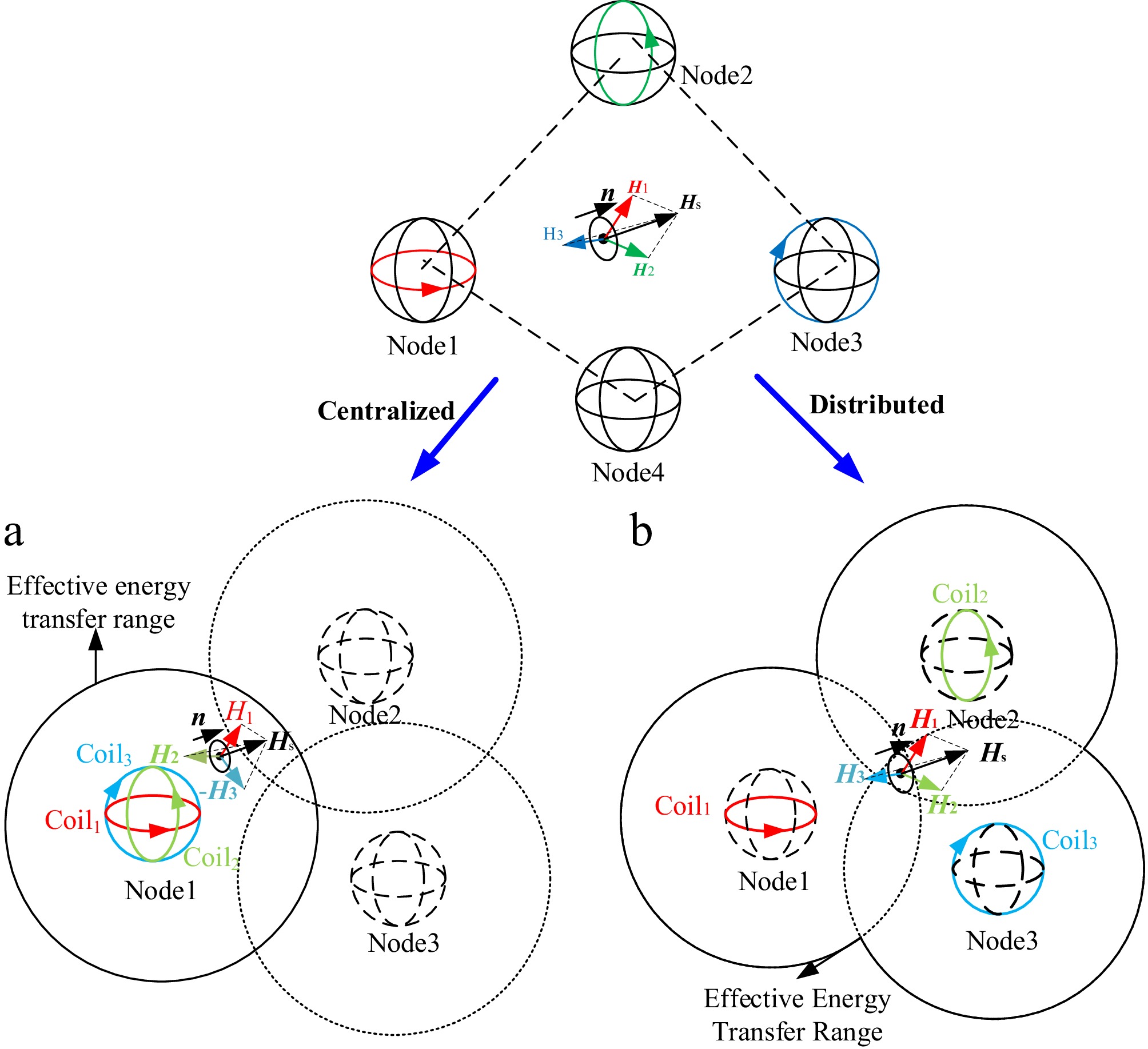
Figure 1.
Multi-node wireless power transfer network architecture. (a) Centralized 3D orthogonal power transfer mode. (b) Distributed 3D orthogonal power transfer mode.
-
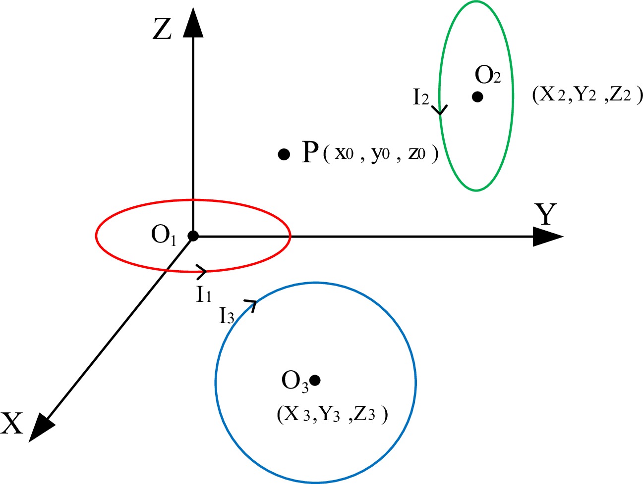
Figure 2.
Schematic diagram of the three orthogonal coils and the receiving center point.
-
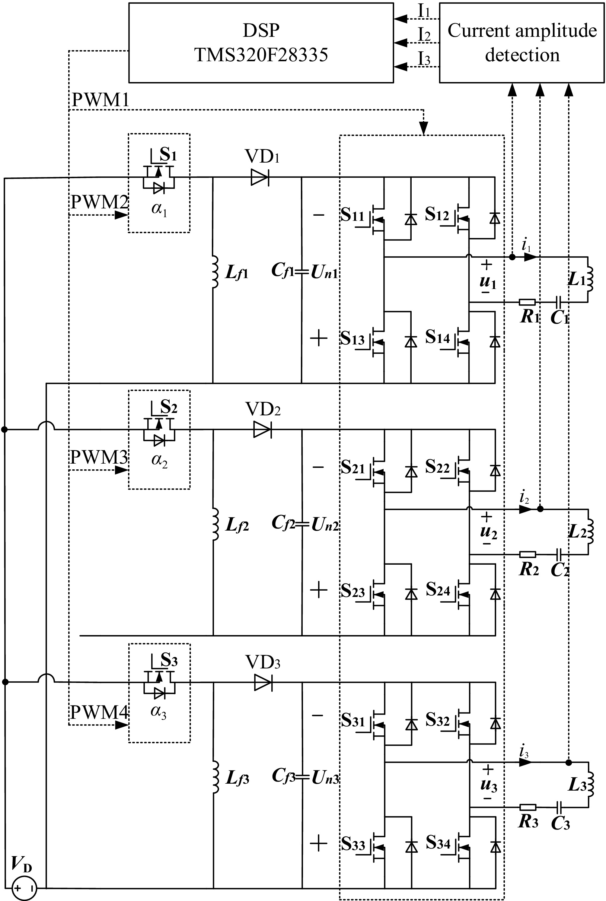
Figure 3.
Excitation current control circuit diagram.
-
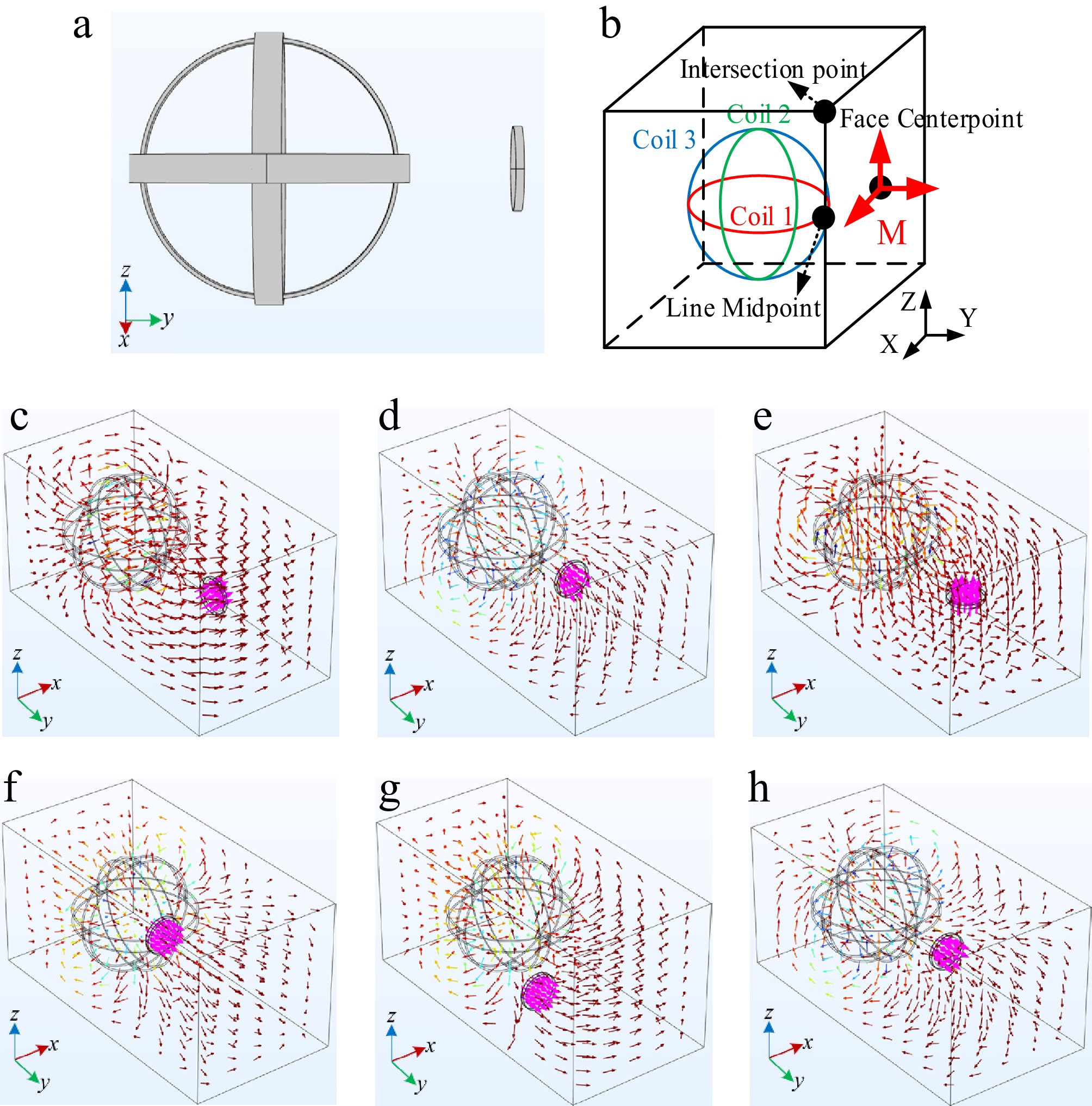
Figure 4.
(a) Centralized energy transfer architecture model. (b) Schematic diagram of magnetic vector direction verification setup for centralized power transfer. (c)−(e) Magnetic vector different direction simulation diagram of centralized architecture. (f)−(h) Simulation diagram of the magnetic vector at different points in the centralized architecture.
-
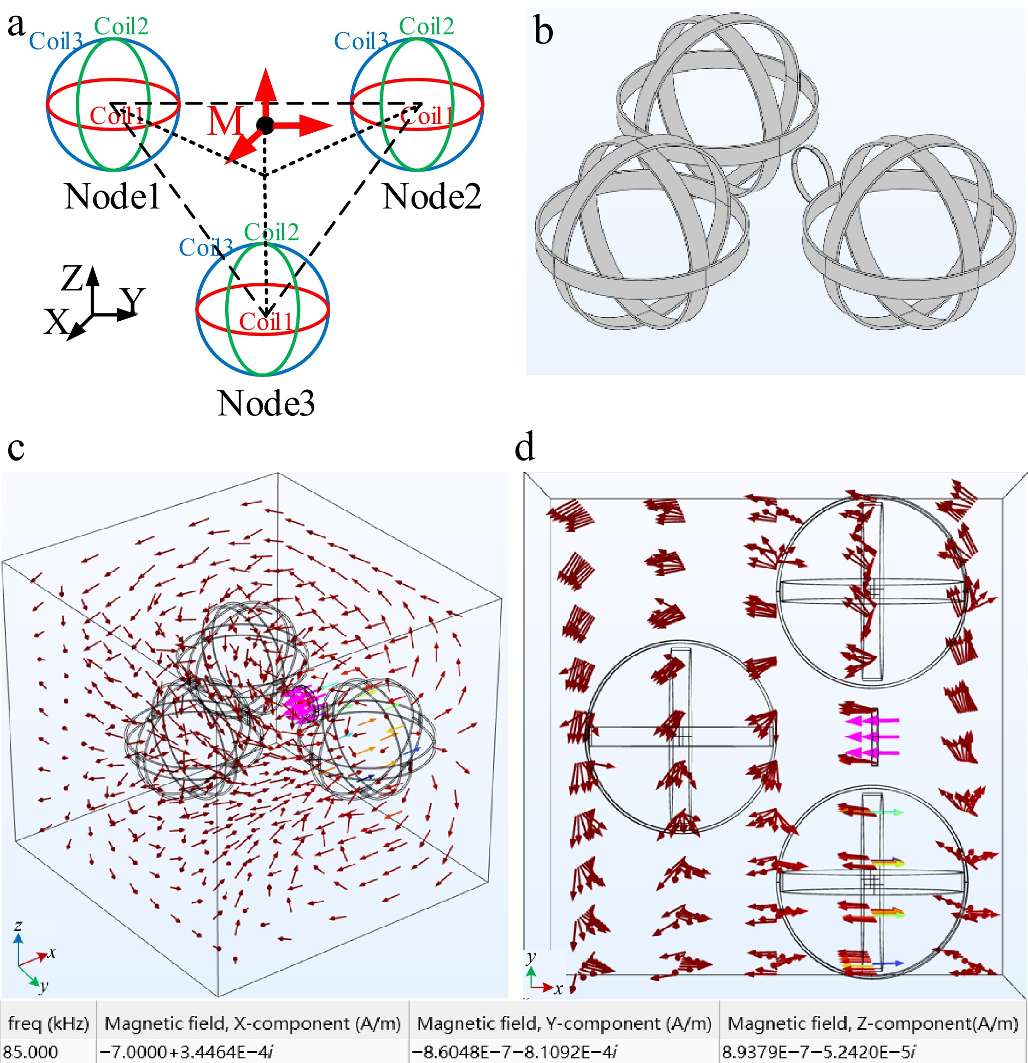
Figure 5.
(a) Spatial diagram of distributed power transfer architecture. (b) Distributed simulation model. (c) Magnetic vector simulation of distributed architecture with expected magnetic field direction in the X direction.(d)Top view of Fig. 5c.
-
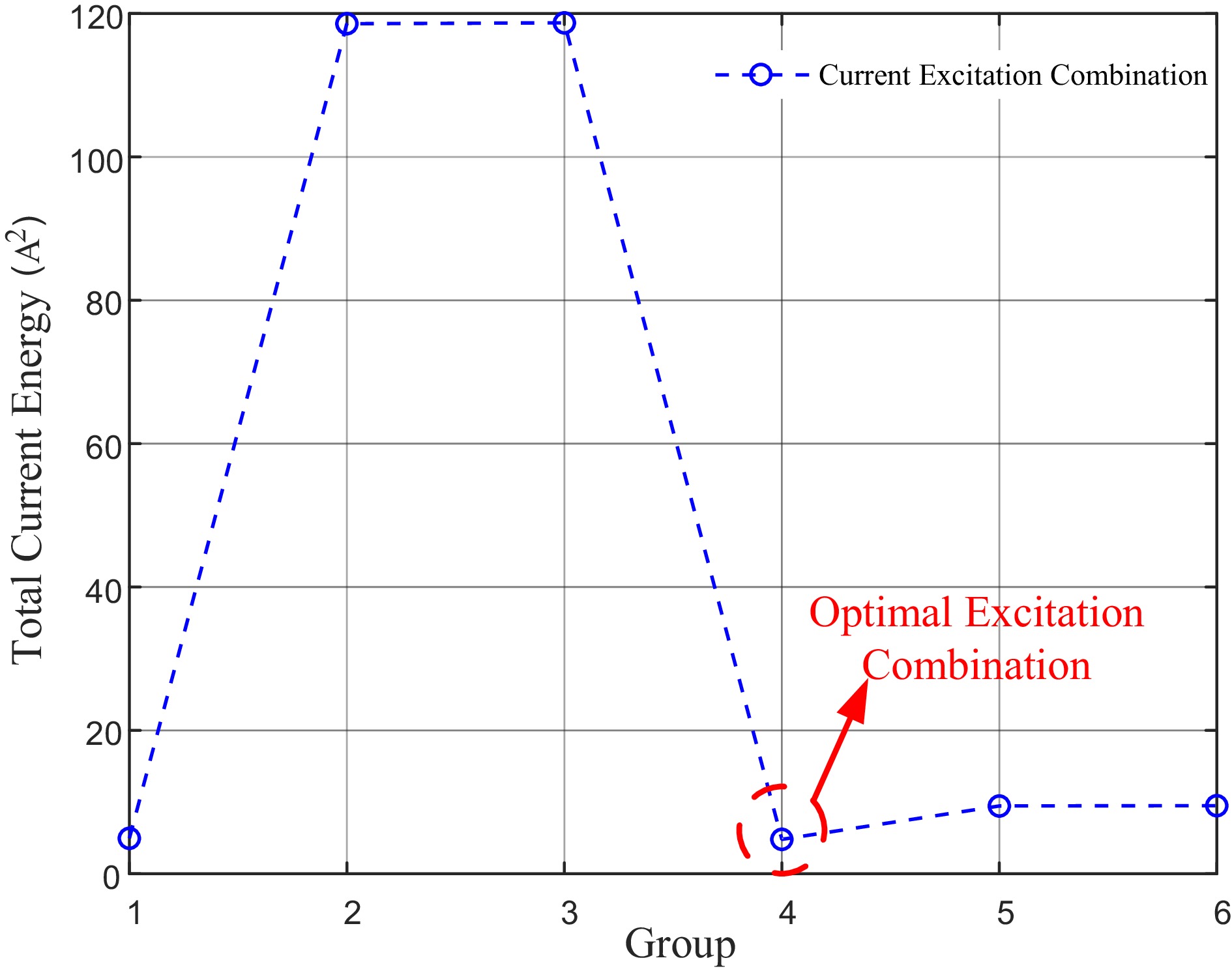
Figure 6.
Line graph of total current power of different current excitation combinations with expected magnetic field direction in the X direction.
-
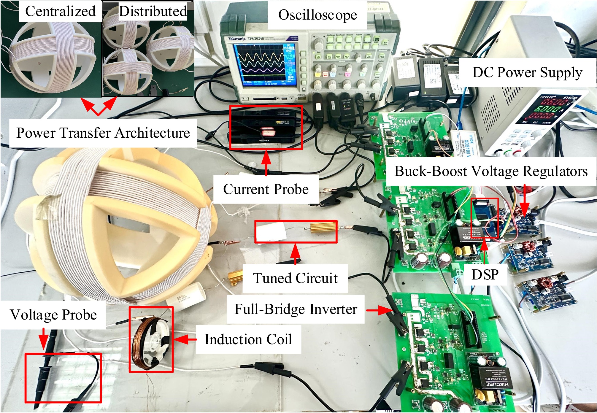
Figure 7.
Schematic diagram of the experimental device for a centralized power transfer system.
-
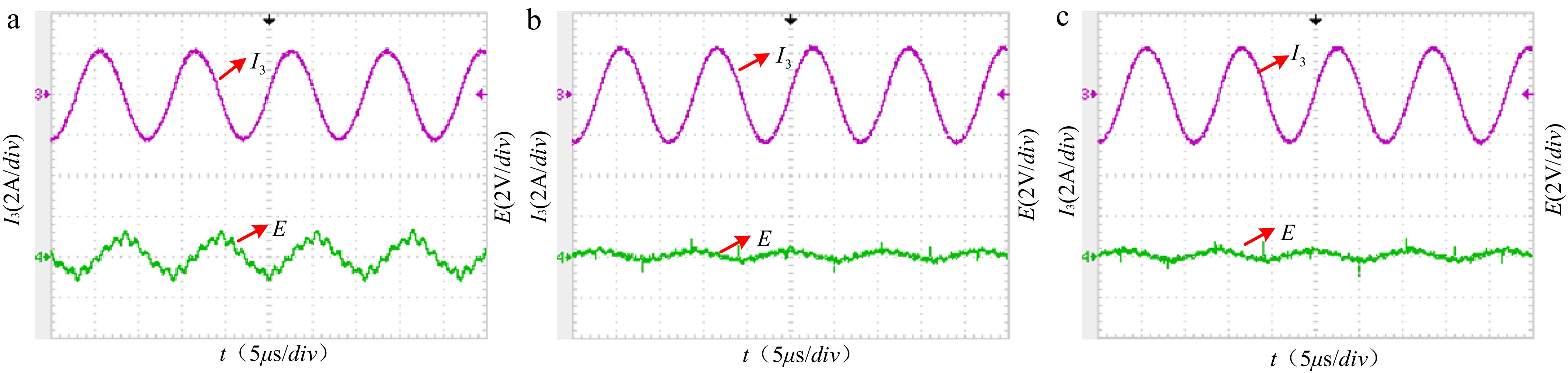
Figure 8.
Experimental waveforms of X, Y, and Z components at point M with the expected magnetic field direction in the X direction.
-
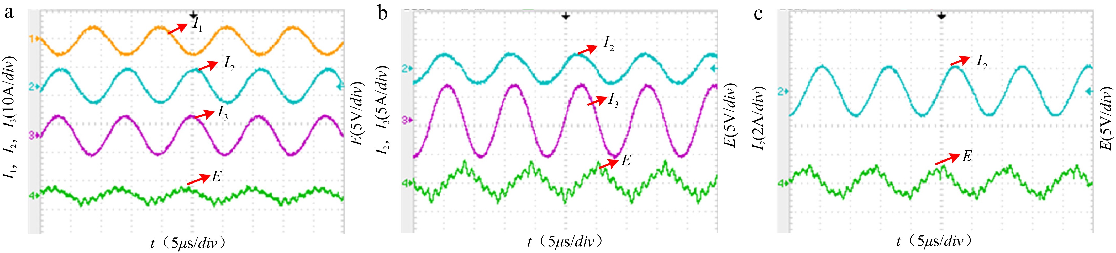
Figure 9.
The experimental waveform diagram at different point.(a)Intersection.(b)Line midpoint.(c)Face centerpoint.
-
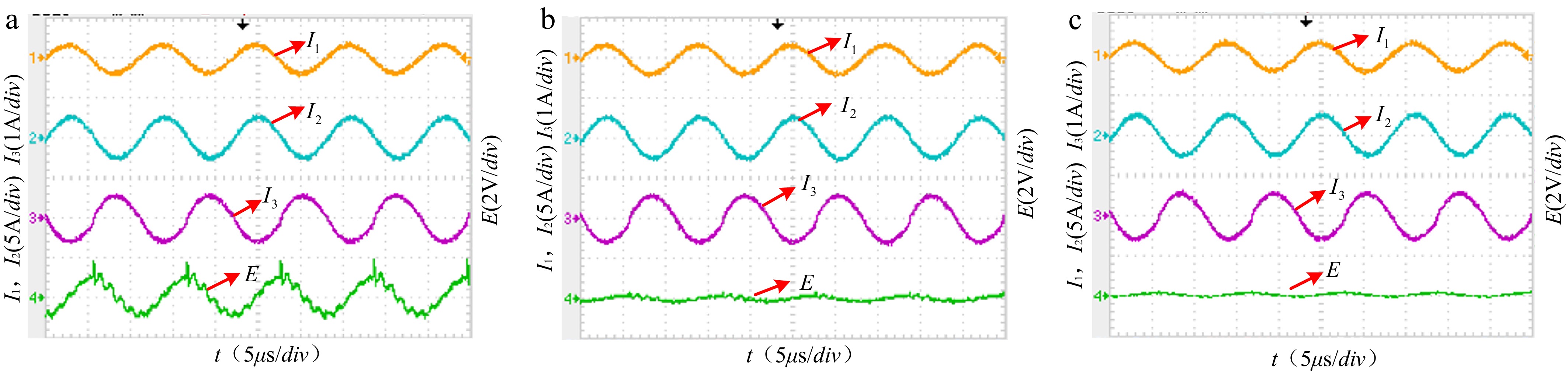
Figure 10.
Experimental waveform plots of magnetic field components in the (a) X, (b) Y, and (c) Z directions at point M.
-
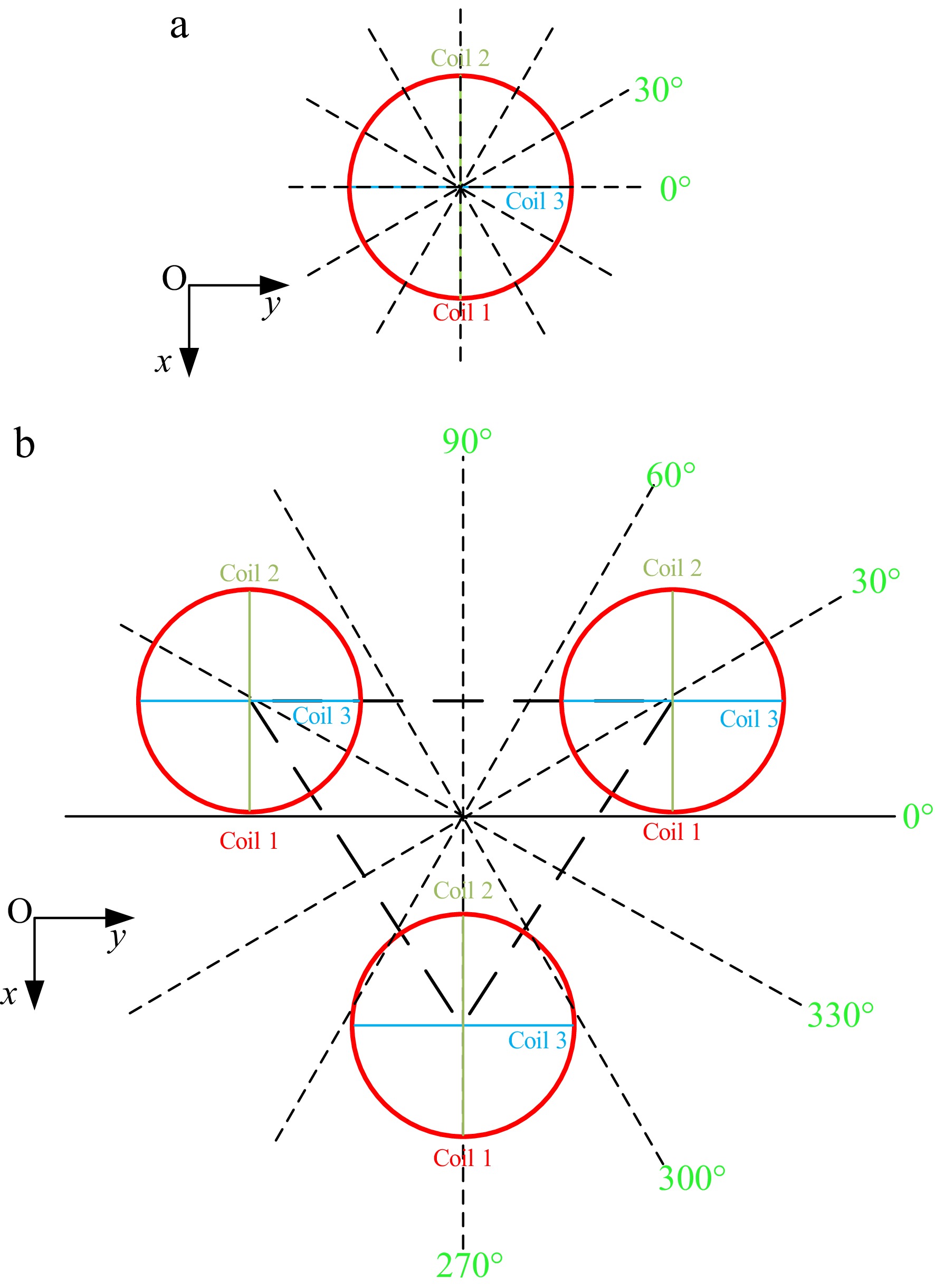
Figure 11.
(a) Centralized and (b) distributed omnidirectional effective power transfer direction schematic diagram.
-
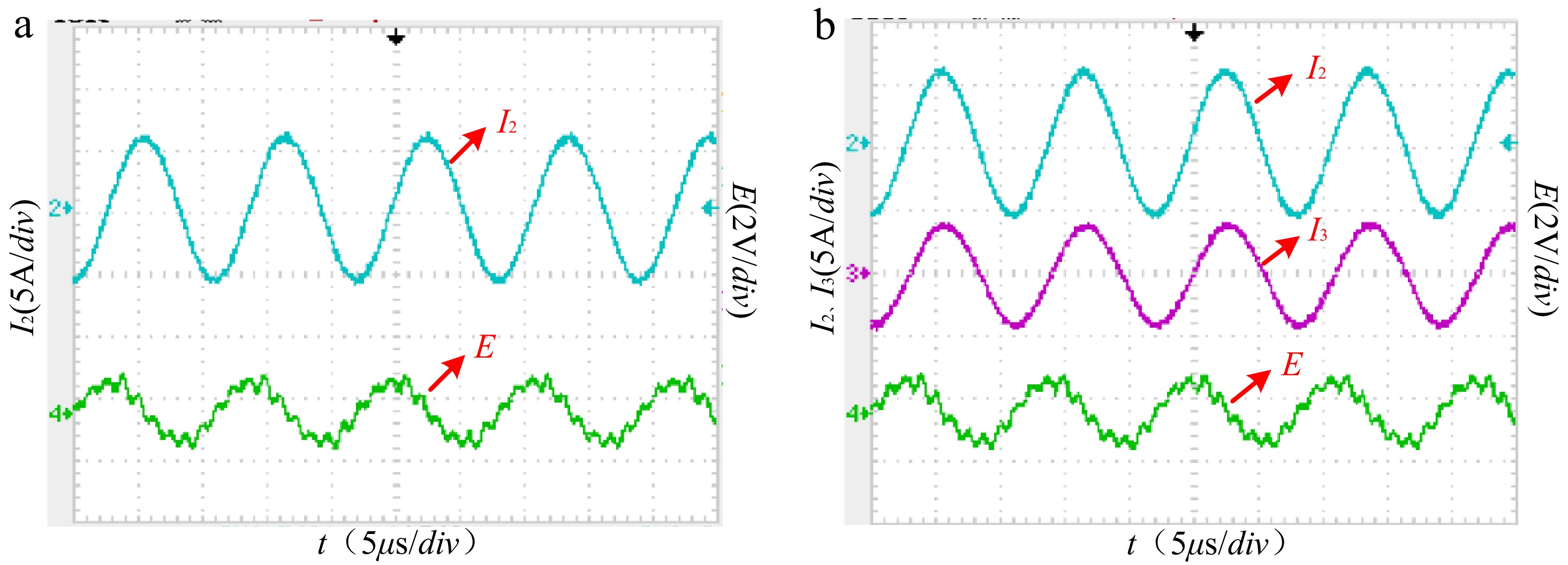
Figure 12.
Waveform of the effective distance test for centralized magnetic energy control system (a) 0°. (b) 30°.
-
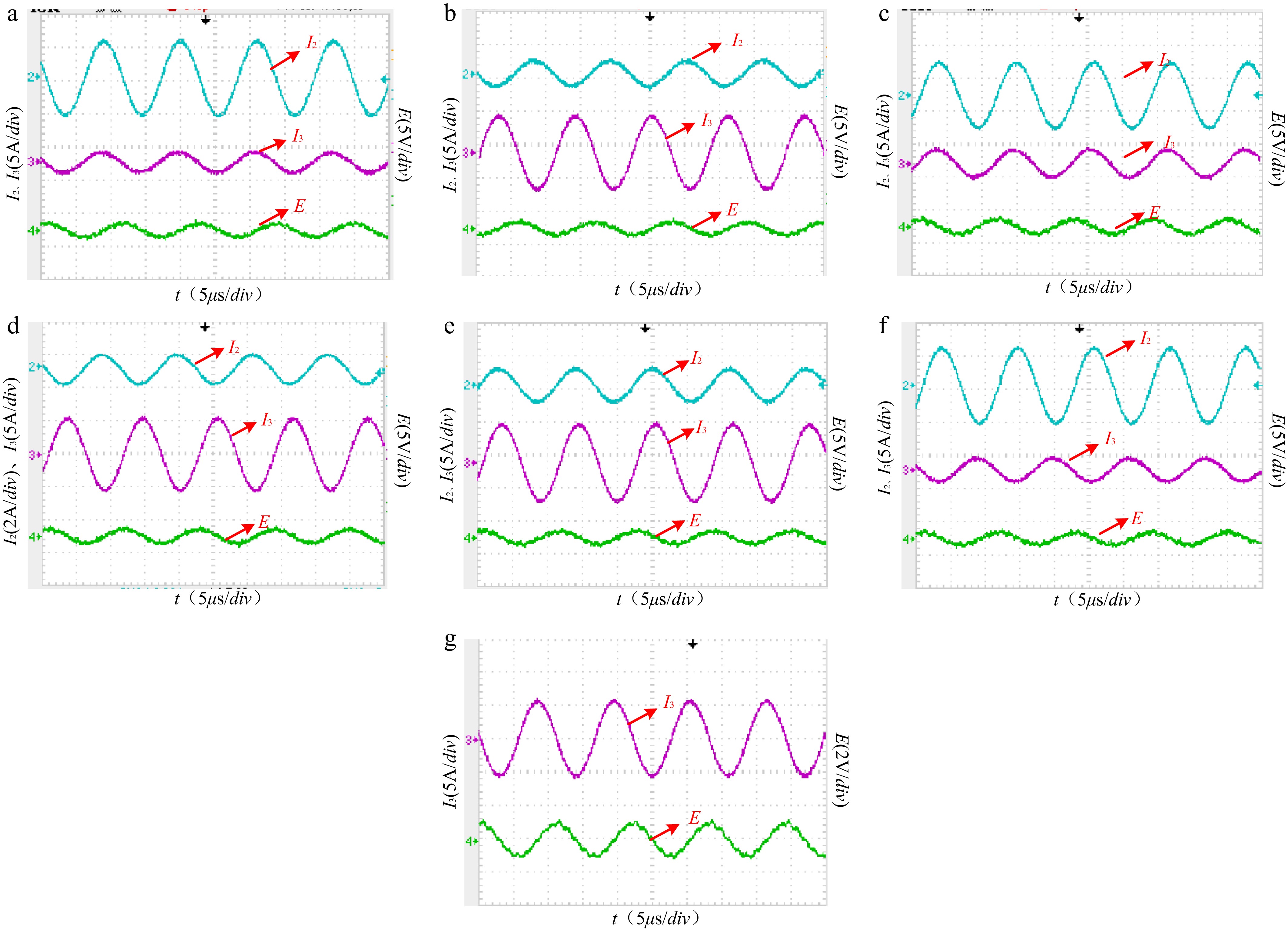
Figure 13.
Waveform of the effective distance test for a distributed magnetic energy control system (a) 90°, (b) 60°, (c) 30°, (d) 0°, (e) 330°, (f) 300°, and (g) 270°.
-
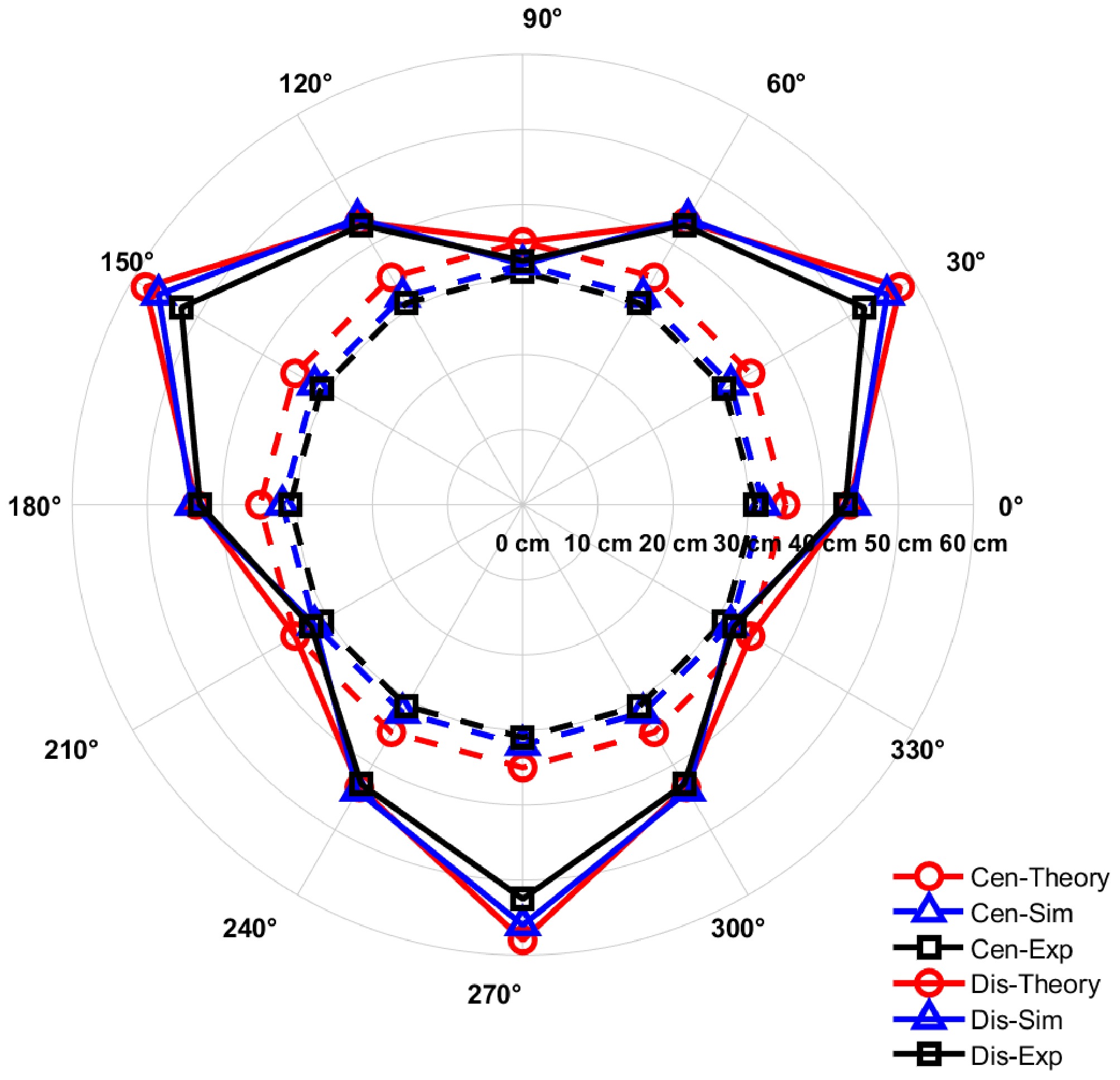
Figure 14.
Effective distance distribution of centralized and distributed magnets.
-
Parameters Values Radius of coil 1(m) 0.11 Radius of coil 2(m) 0.1 Radius of coil 3(m) 0.09 Number of turns(N) 14 Radius of the receiving Coil(m) 0.05 Position of the receiving Coil (x0, y0, z0) (0, 0.2, 0) Normal vector of the receiving coil (A, B, C) (0, 1, 0) Table 1.
Centralized power transfer architecture parameter setting.
-
Position of the
field pointIntended magnetic
field directionIntended
magnetic field
magnitude (A/m)I1(A) I2(A) I3(A) M X 7 0 0 1.56 M Y 7 0 1.11 0 M Z 7 −0.91 0 0 Table 2.
Current parameter settings for field direction control validation.
-
Table 3.
Size of magnetic vector at different direction in centralized architecture.
-
Point Experimental
magnetic
field magnitude
(A/m)Desired
magnetic
field magnitude
(A/m)I1(A) I2(A) I3(A) (a) Intersection point Y 7 3.5 −4.2 −5.2 (b) Line midpoint Y 7 0 −1.6 −4.8 (c) Face centerpoint Y 7 0 1.11 0 Table 4.
The magnetic field size control verifies the current parameter setting.
-
Point Freq (kHz) X-component (A/m) Y-component (A/m) Z-component (A/m) (a) Intersection point 91 0.31123 6.9856 0.40862 (b) Line midpoint 91 0.10435 6.9577 0.00367 (c) Face centerpoint 91 −0.01346 7.0007 0.00093 Table 5.
Size of magnetic vector at different point in centralized architecture.
-
Parameters Values Node 1 location (X1, Y1, Z1) (−0.144, −0.2, 0) Node 2 location (X2, Y2, Z2) (−0.144, 0.2, 0) Node 3 location (X3, Y3, Z3) (0.2, 0, 0) Receiving coil position (x0, y0, z0) (0, 0, 0.1) Table 6.
Set distributed power transfer architecture parameters.
-
Group Position of Coil 1 Position of Coil 2 Position of Coil 3 Intended direction Intended magnitude I1(A) I2(A) I3(A) 1 Q1 Q2 Q3 X 7 A/m 1.18 −1.84 −0.4 2 Q1 Q3 Q2 X 7 A/m 6.26 −1.4 −8.8 3 Q2 Q3 Q1 X 7 A/m 6.27 1.4 −8.8 4 Q2 Q1 Q3 X 7 A/m 1.18 1.8 −0.4 5 Q3 Q1 Q2 X 7 A/m −2.37 1.6 1.13 6 Q3 Q2 Q1 X 7 A/m −2.37 −1.62 1.12 Table 7.
A set of current combination parameters for a distributed architecture with an expected magnetic field direction in the X direction.
-
Parameters Values Inductance (μH) 64 Resistance (Ω) 0.1 Capacitance (nF) 47.2 Series resistance (Ω) 1 Number of turns (N) 123 Voltage (V) 10 Table 8.
System circuit parameter settings.
-
Point Experimental
magnetic field
magnitude (A/m)Desired magnetic
field magnitude
(A/m)Error (%) (a) Intersection point 6.47 7 7.6 (b) Line midpoint 6.53 7 6.7 (c) Face centerpoint 6.67 7 4.7 Table 9.
Magnetic vector size verification.
-
Angle I1(A) I2(A) I3(A) 0° 0 4 0 30° 0 4 3 Table 10.
Parameter setting of effective power transfer range for centralized power transfer system.
-
Angle I1(A) I2(A) I3(A) 90° 0 −3.8 −1.2 60° 0 −1.3 4 30° 0 3.6 1.4 0° 0 0.6 −3.8 330° 0 1.8 4 300° 0 4 −1.1 270° 0 0 −4 Table 11.
Set effective power transfer range parameters for distributed power transfer system.
Figures
(14)
Tables
(11)