-
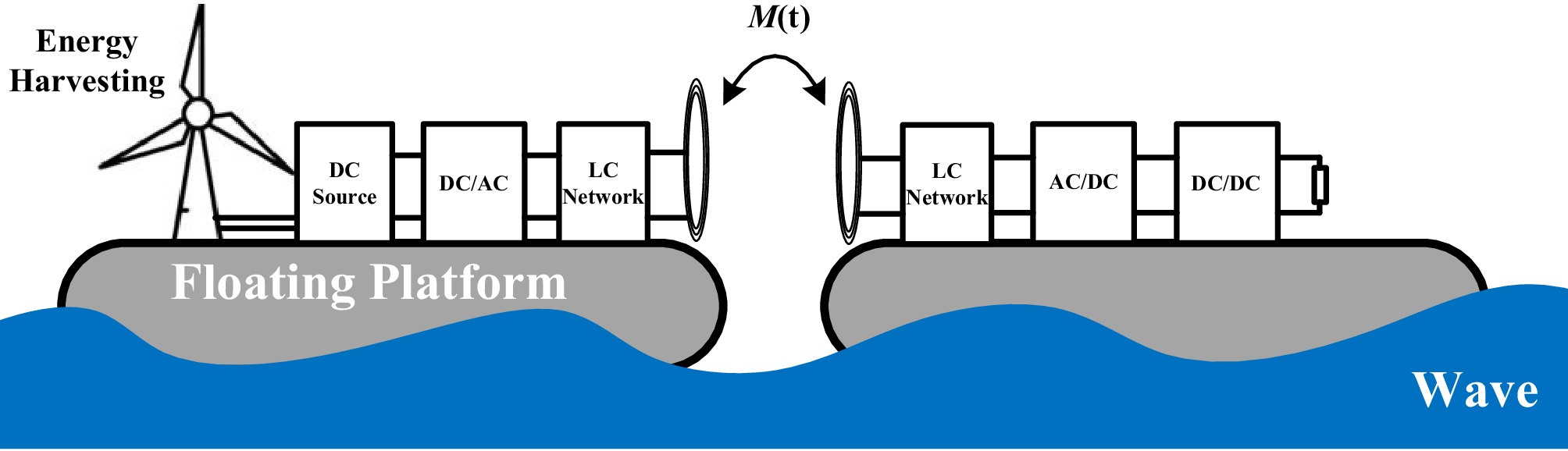
Figure 1.
The schematic diagram of an offshore floating platform system with energy harvesting and WPT capabilities.
-
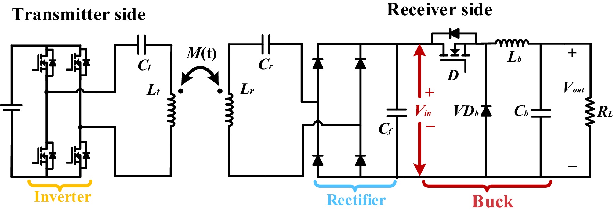
Figure 2.
WPT System topology with Buck converter and time-varying mutual inductance.
-
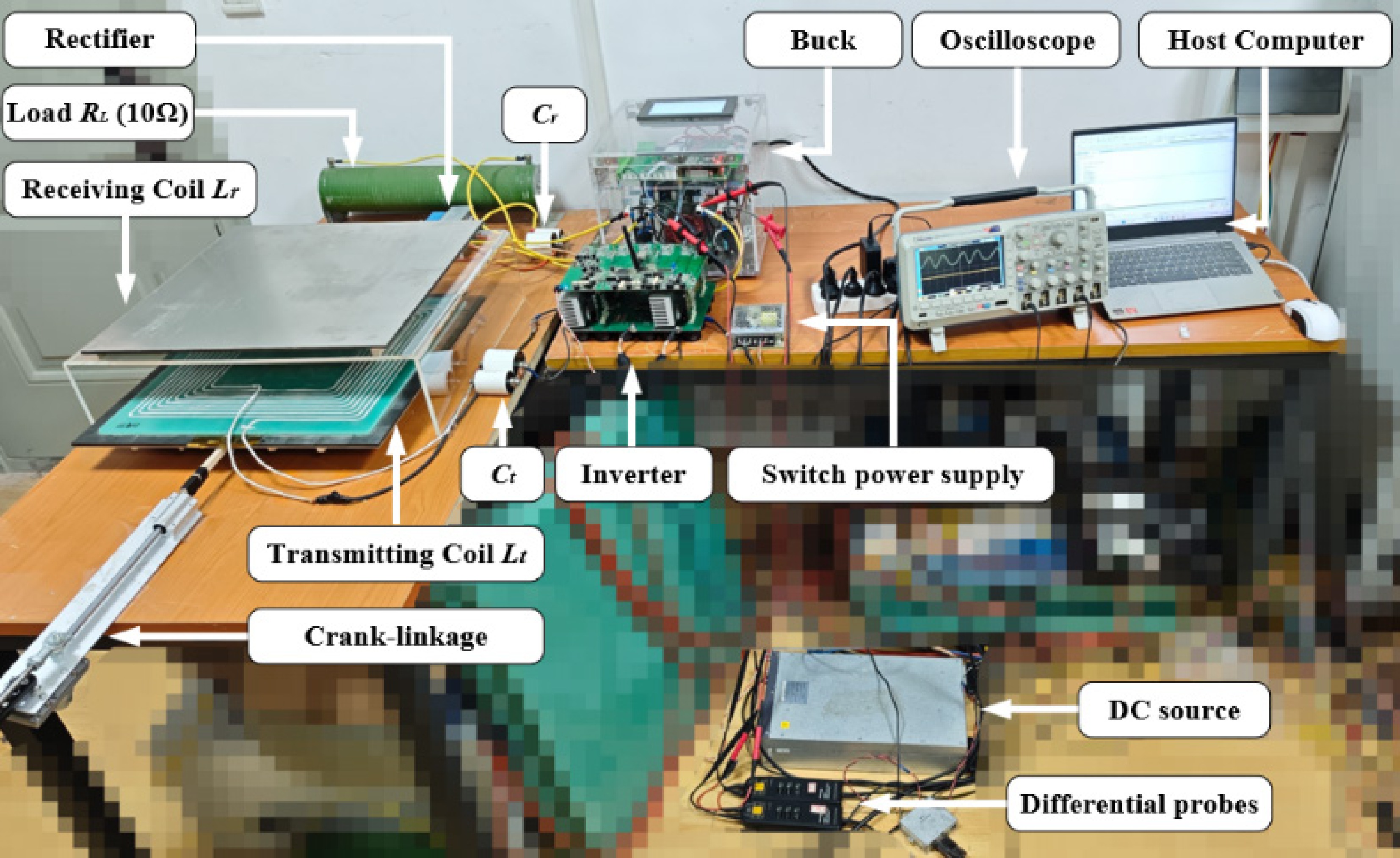
Figure 3.
The prototype for experimental validation (with the coil lateral misalignment).
-
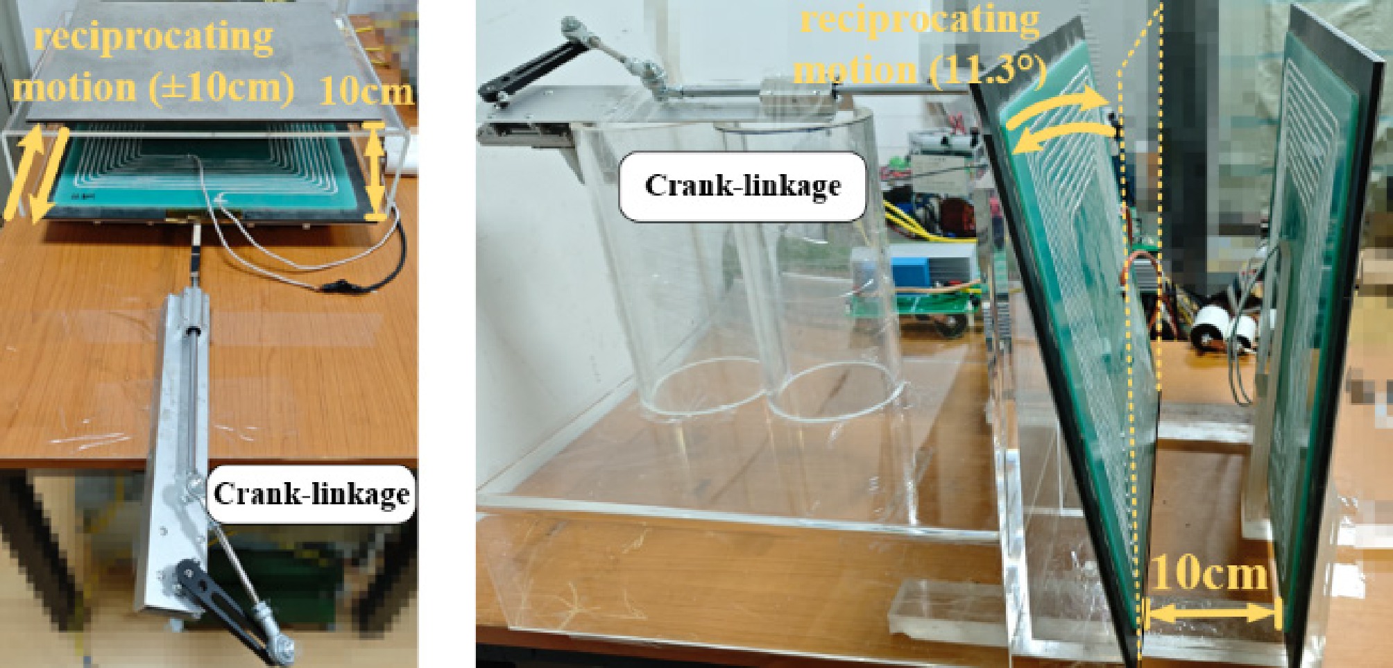
Figure 4.
Implementation of coil lateral misalignment (left) and angular variation (right).
-
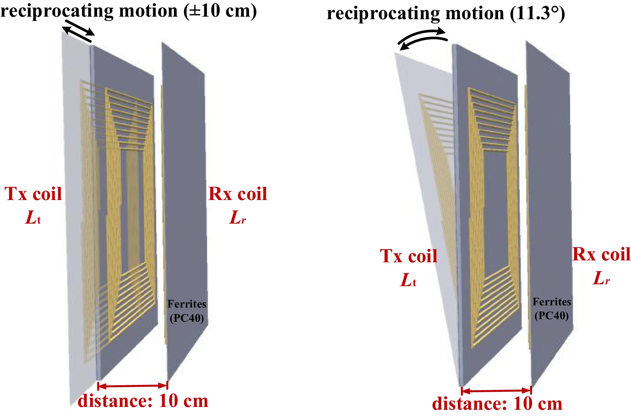
Figure 5.
Schematic of the lateral misalignment (left) and angular variation (right).
-
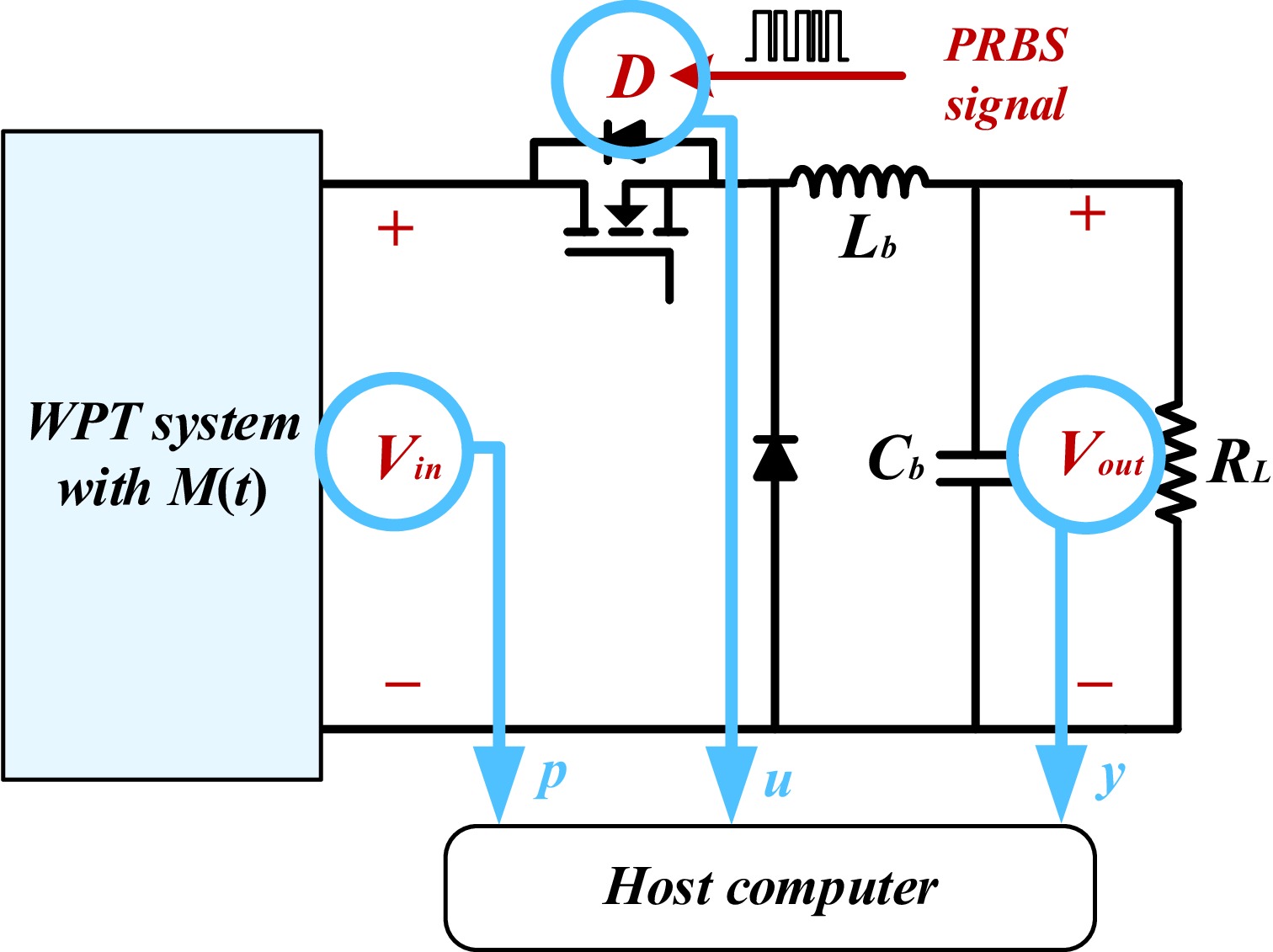
Figure 6.
The PRBS injection and data sampling procedure.
-
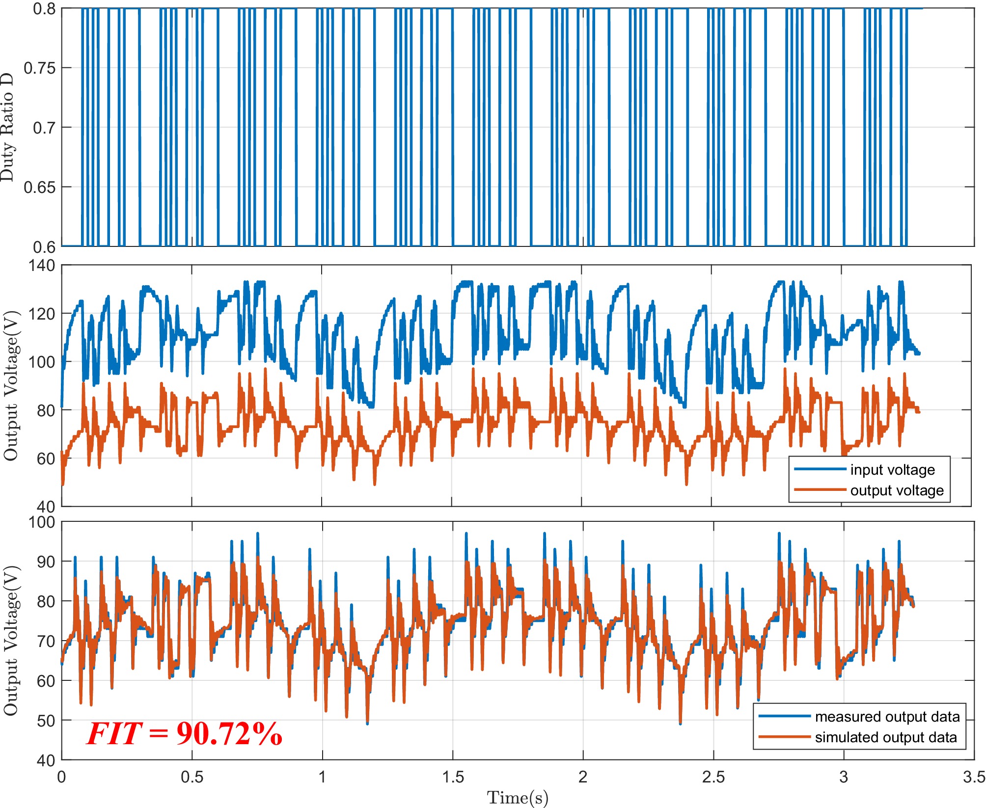
Figure 7.
The sampled dataset DS (1st and 2nd subplots), and the FIT value of the model G(z−1, k) (3rd subplot).
-
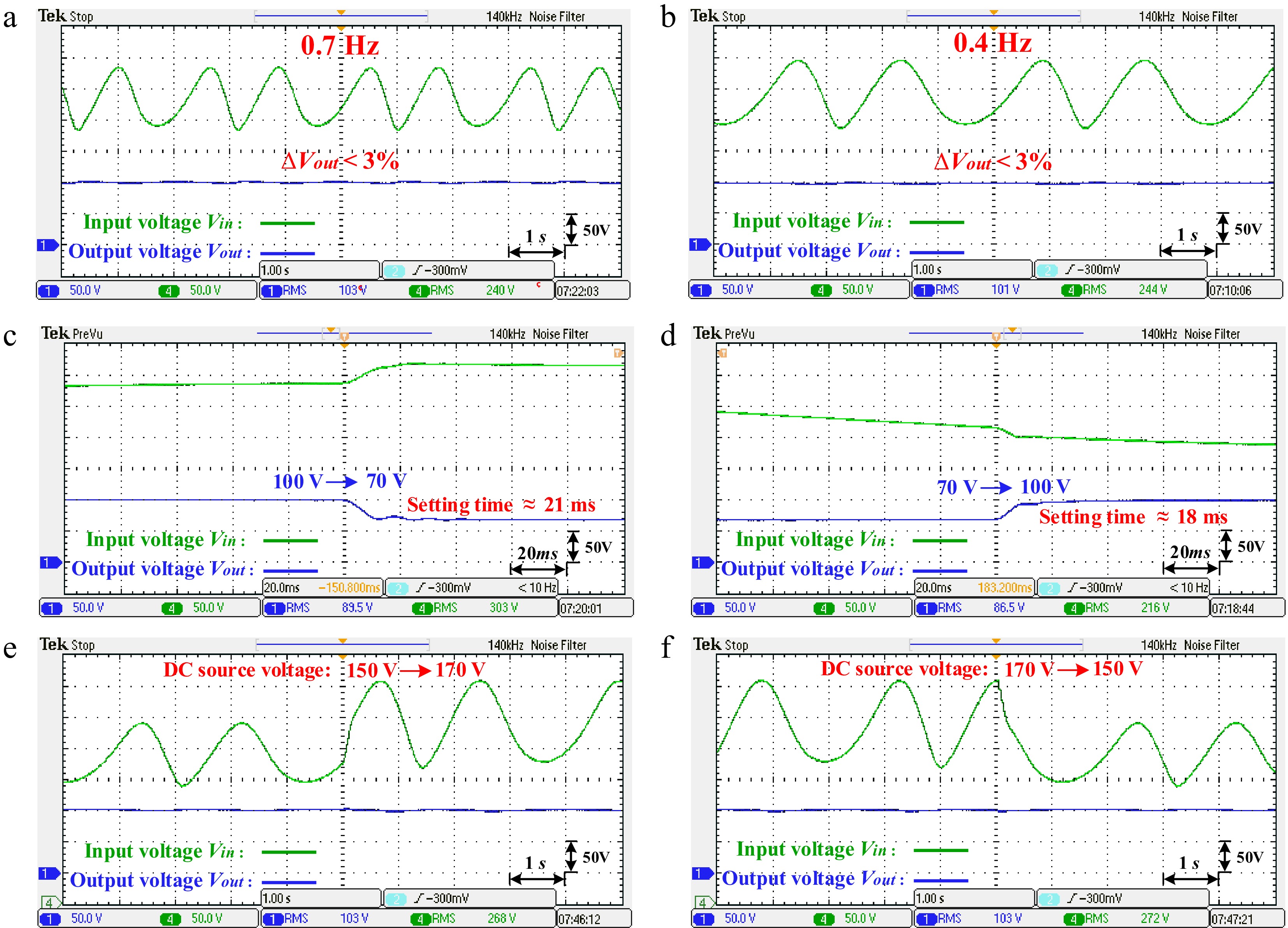
Figure 8.
Experimental results under lateral coil misalignment. (a) Constant voltage output 100 V under motion frequency 0.7 Hz; (b) constant voltage output 100 V under motion frequency 0.4 Hz; (c) the step response results when Vout changed from 100 to 70 V; (d) the step response results when Vout changed from 70 to 100 V; (e) constant voltage output 100 V when DC source voltage Vdc changed from 150 to 170 V; (f) constant voltage output 100 V when DC source voltage Vdc changed from 170 to 150 V.
-
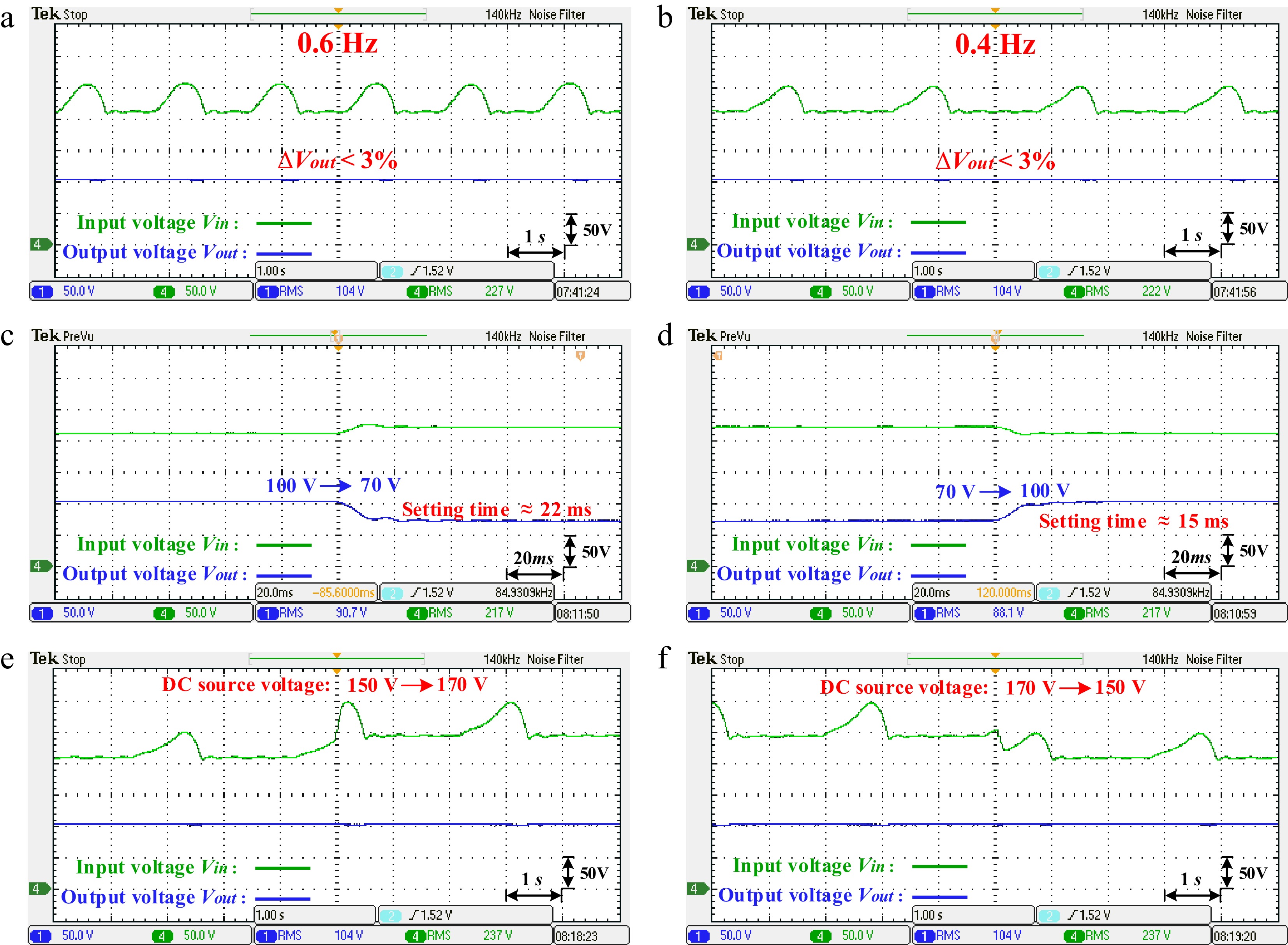
Figure 9.
Experimental results under angular variation of coil. (a) Constant voltage output 100 V under motion frequency 0.6 Hz; (b) constant voltage output 100 V under motion frequency 0.4 Hz; (c) the step response results when Vout changed from 100 to 70 V; (d) the step response results when Vout changed from 70 to 100 V; (e) constant voltage output 100 V when DC source voltage Vdc changed from 150 to 170 V; (f) constant voltage output 100 V when DC source voltage Vdc changed from 170 to 150 V;
-
Parameter Explanation Value Vdc DC voltage 150 V Ct Resonant capacitor of transmitter side 53.1 nF Lt Self-inductance of the transmitting coil 66 μH Cr Resonant capacitor of receiver side 53.1 nF Lr Self-inductance of the receiving coil 66 μH Cf Filter Capacitor of the rectifier 50 μF Lb Inductor of Buck 1 mH Cb Capacitor of Buck 9.4 μF RL Load resistance 10 Ω finv Switching frequency of the inverter 85 kHz fb Switching frequency of Buck 15 kHz Table 1.
Circuit component parameters.
Figures
(9)
Tables
(1)