-
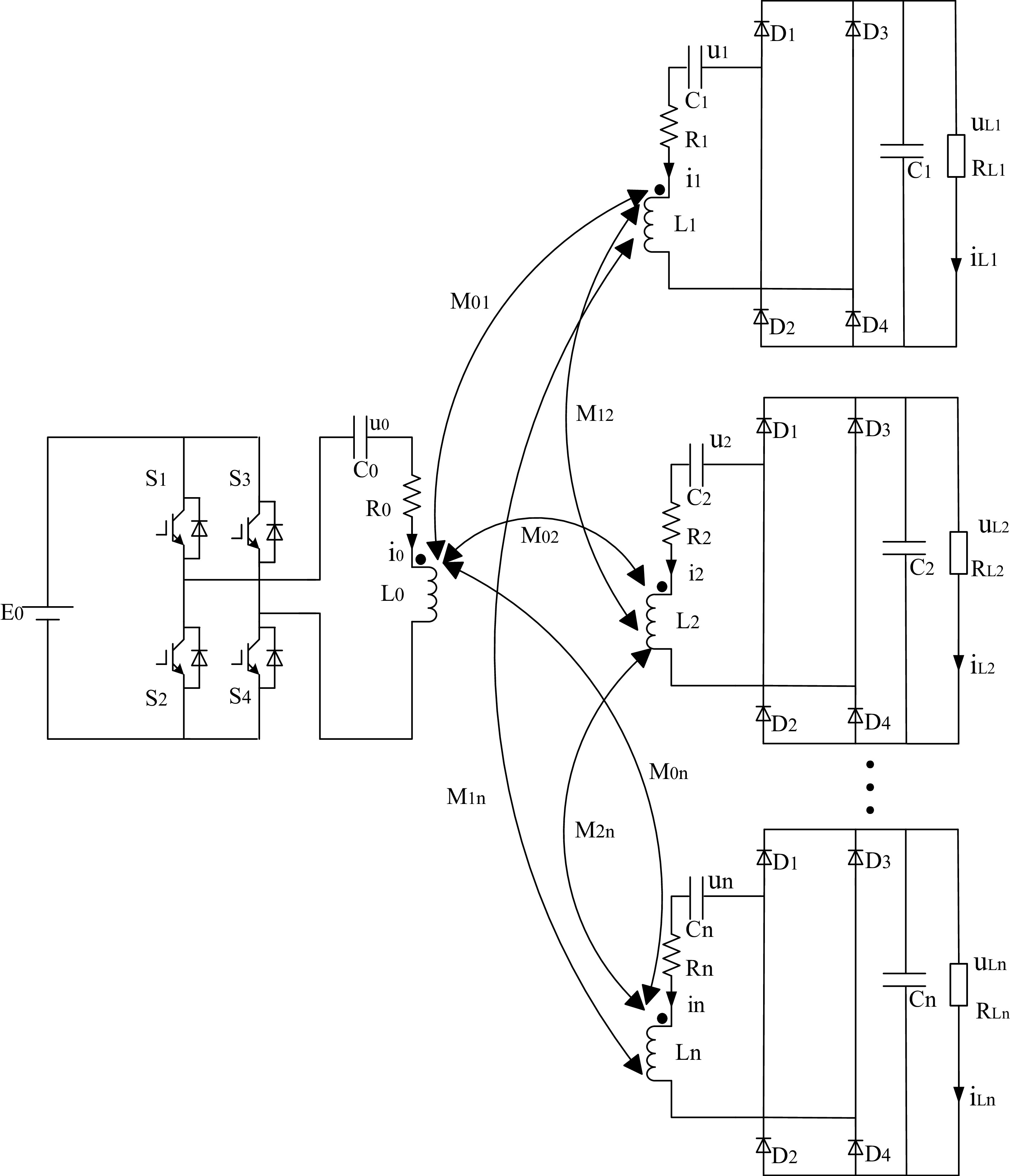
Figure 1.
WPT system with multiple receivers.
-
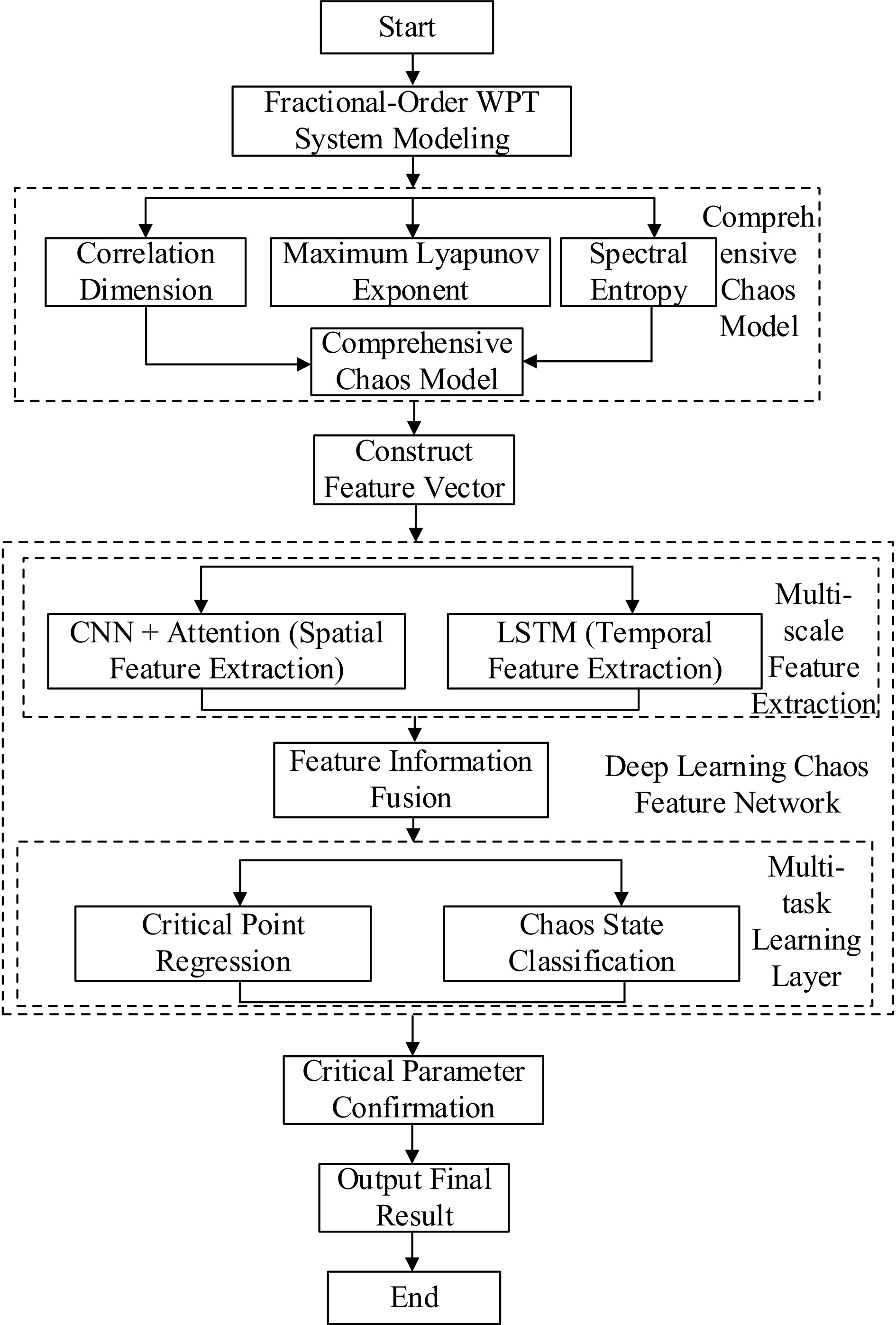
Figure 2.
Flowchart of system chaotic critical parameter identification.
-
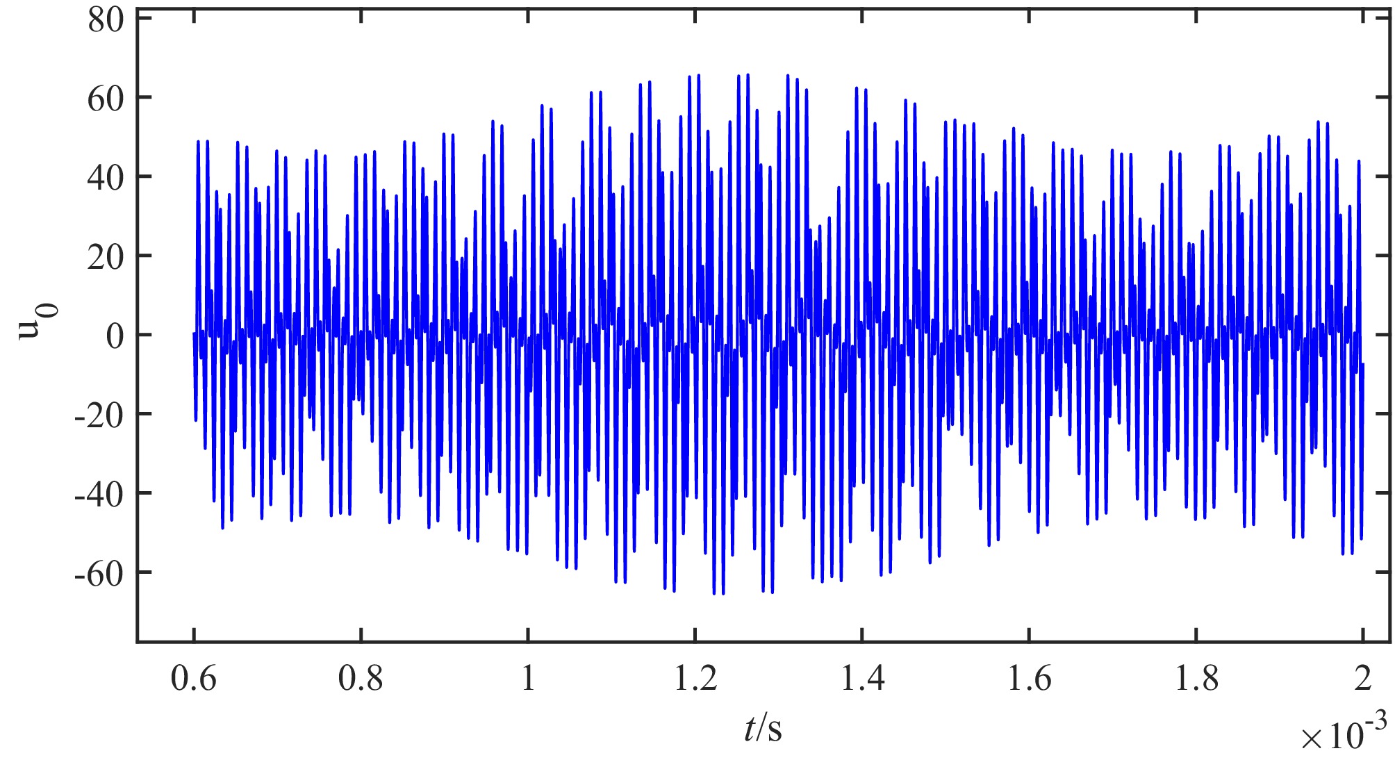
Figure 3.
Voltage state response of the transmitter.
-
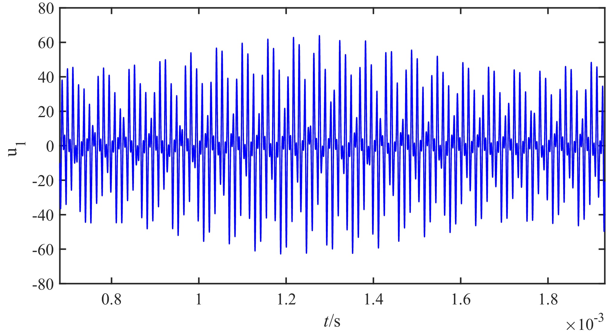
Figure 4.
Voltage state response of receiver 1.
-
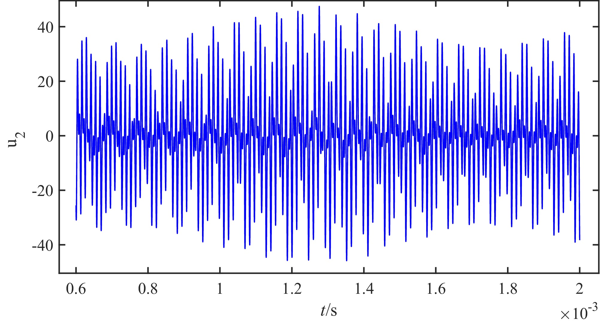
Figure 5.
Voltage state response of receiver 2.
-
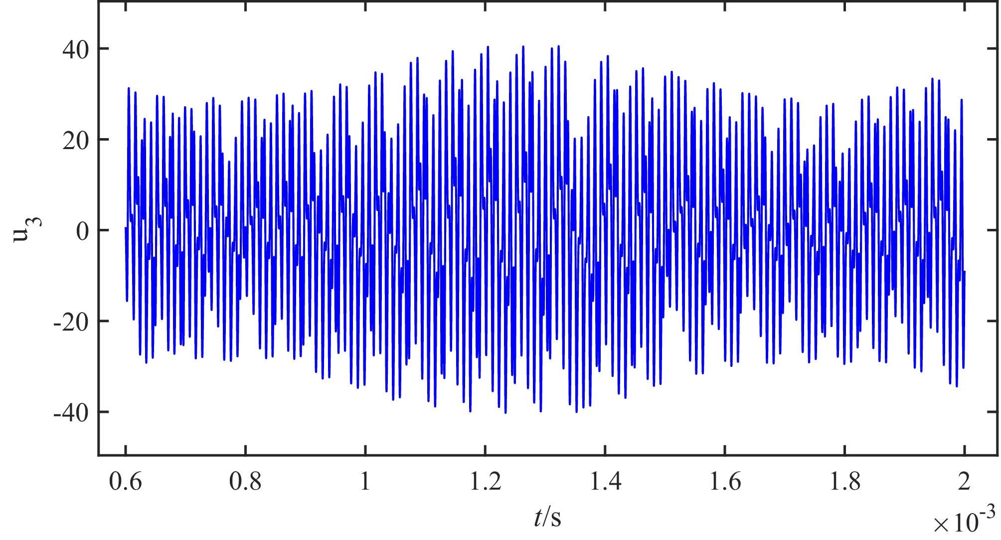
Figure 6.
Voltage state response of receiver 3.
-
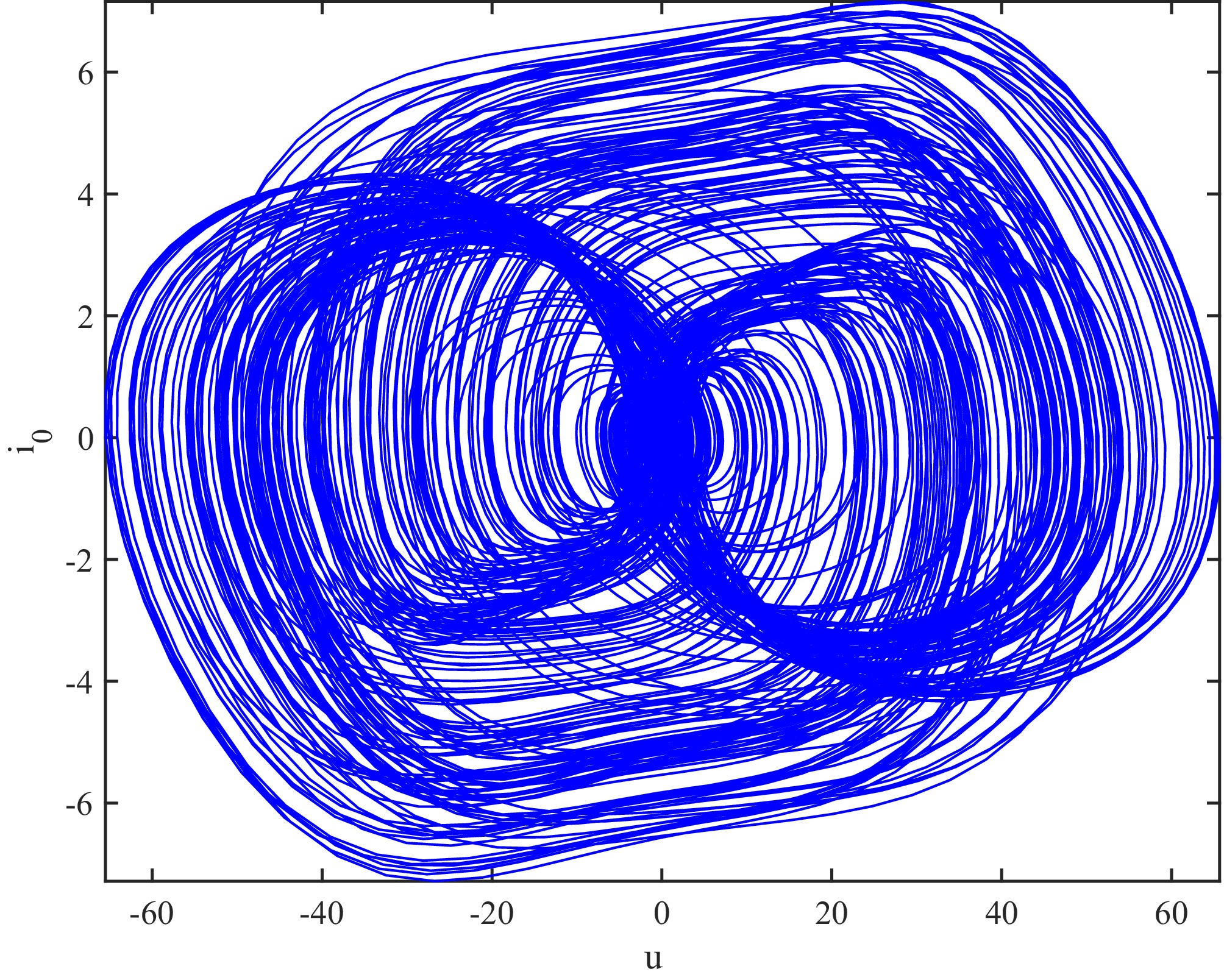
Figure 7.
Phase trajectory of the transmitter.
-
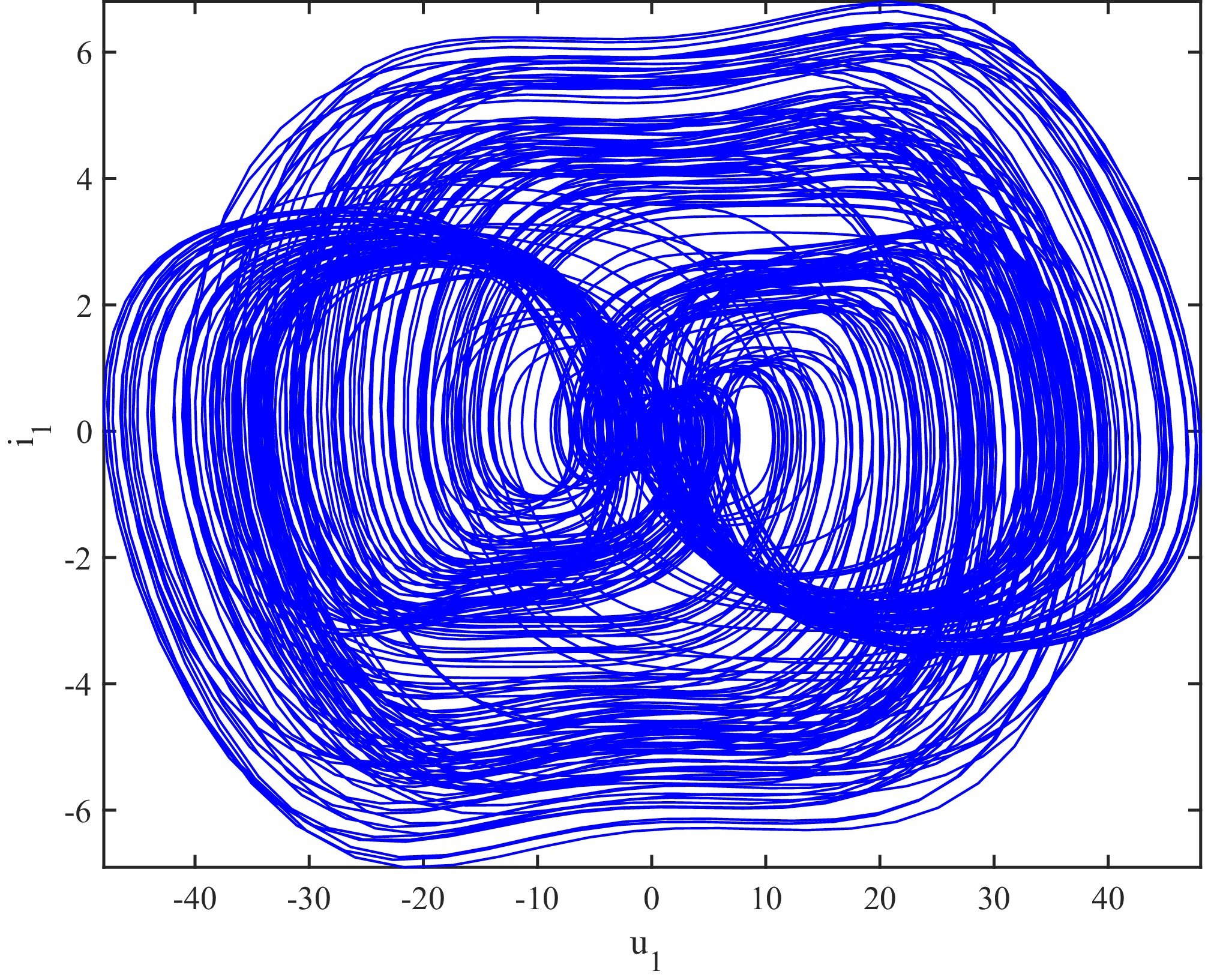
Figure 8.
Phase trajectory of receiver 1.
-
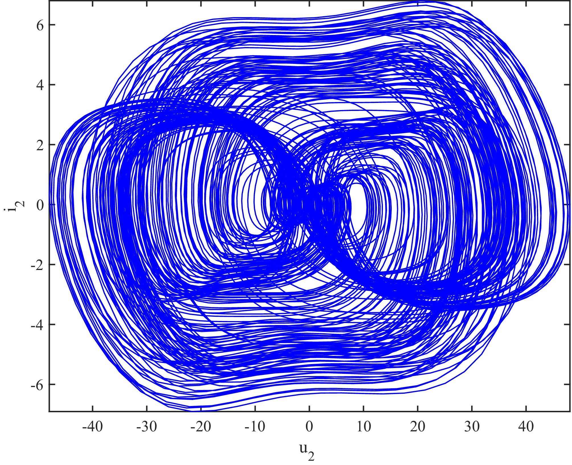
Figure 9.
Phase trajectory of receiver 2.
-
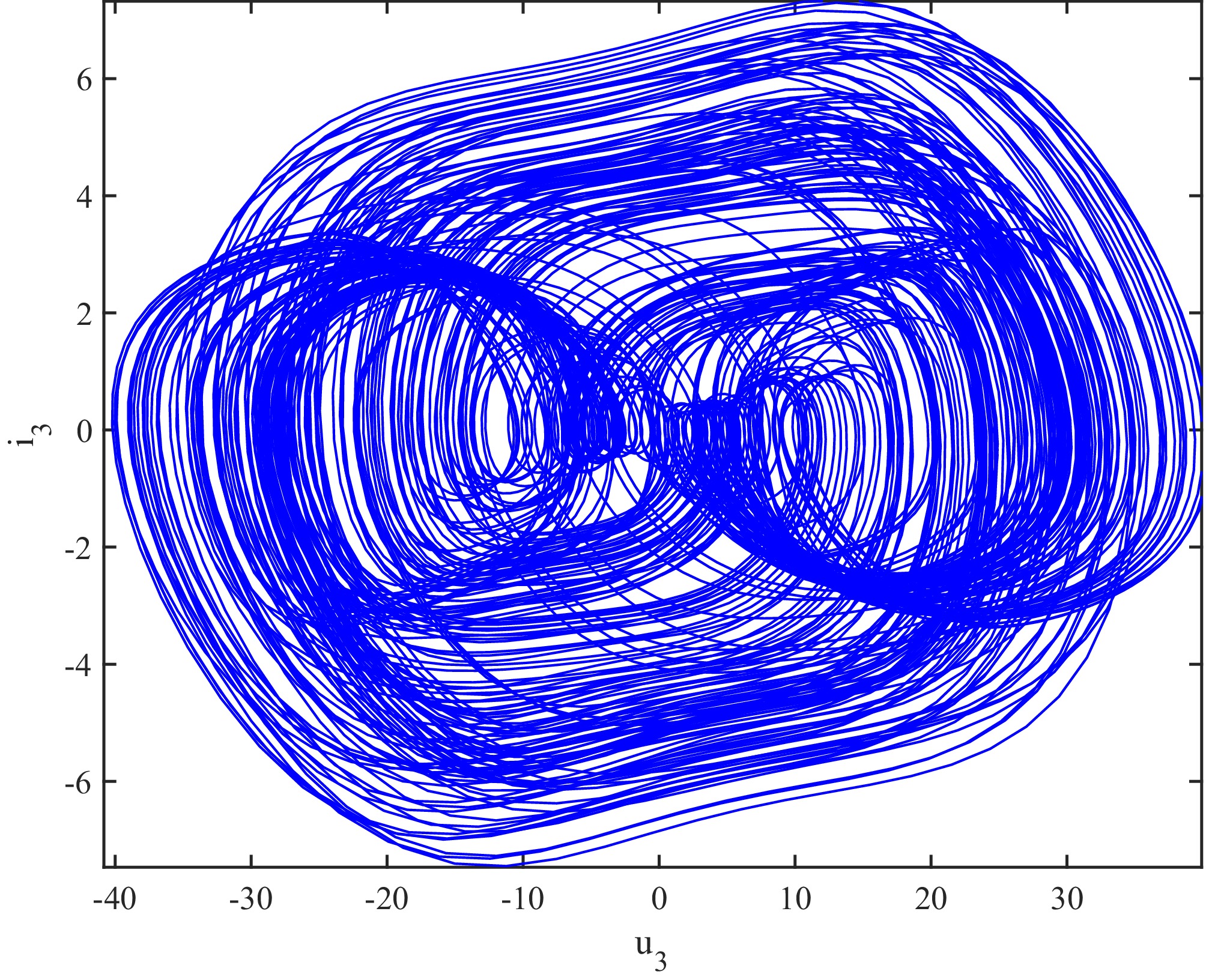
Figure 10.
Phase trajectory of receiver 3.
-
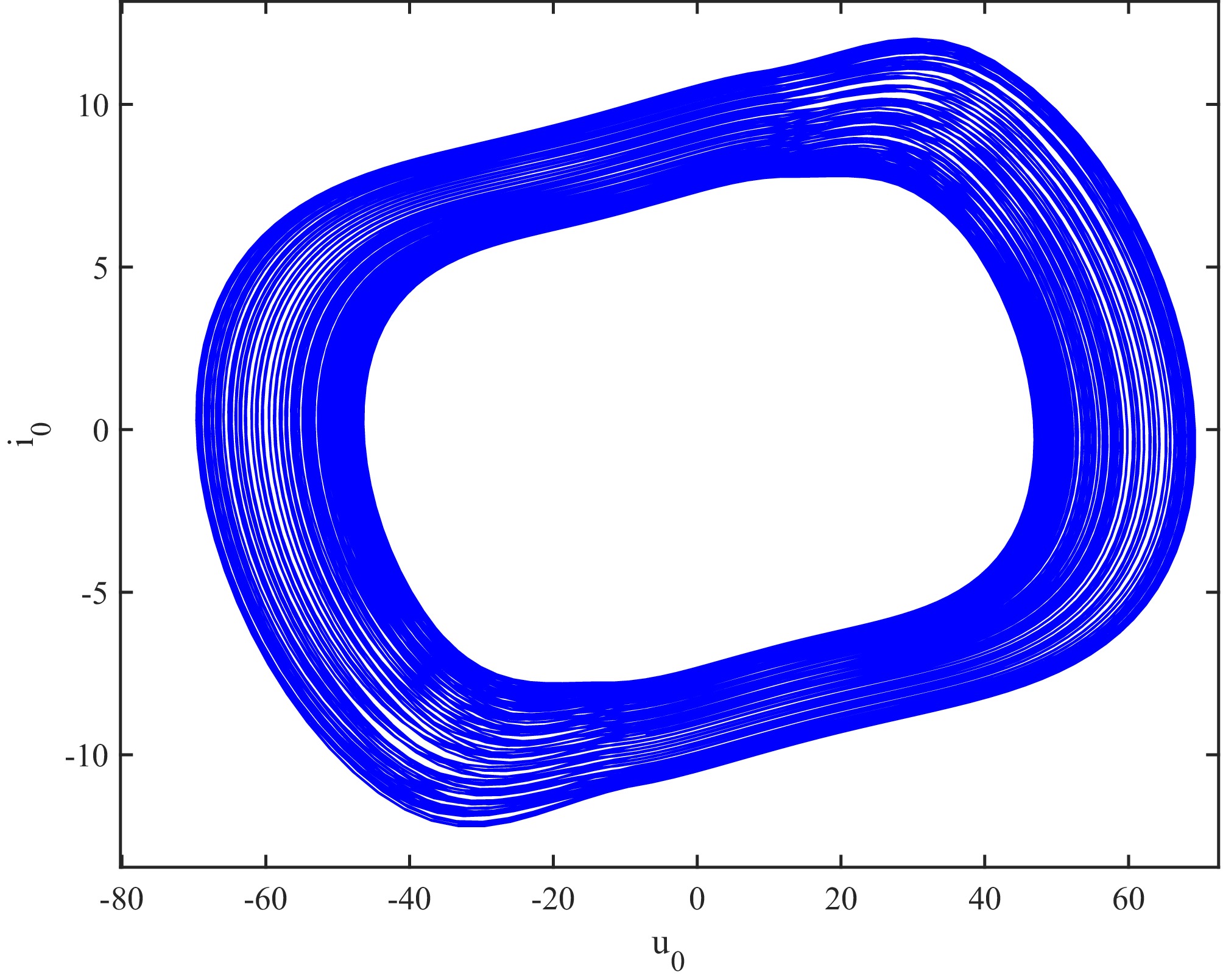
Figure 11.
Phase trajectory of the transmitter.
-
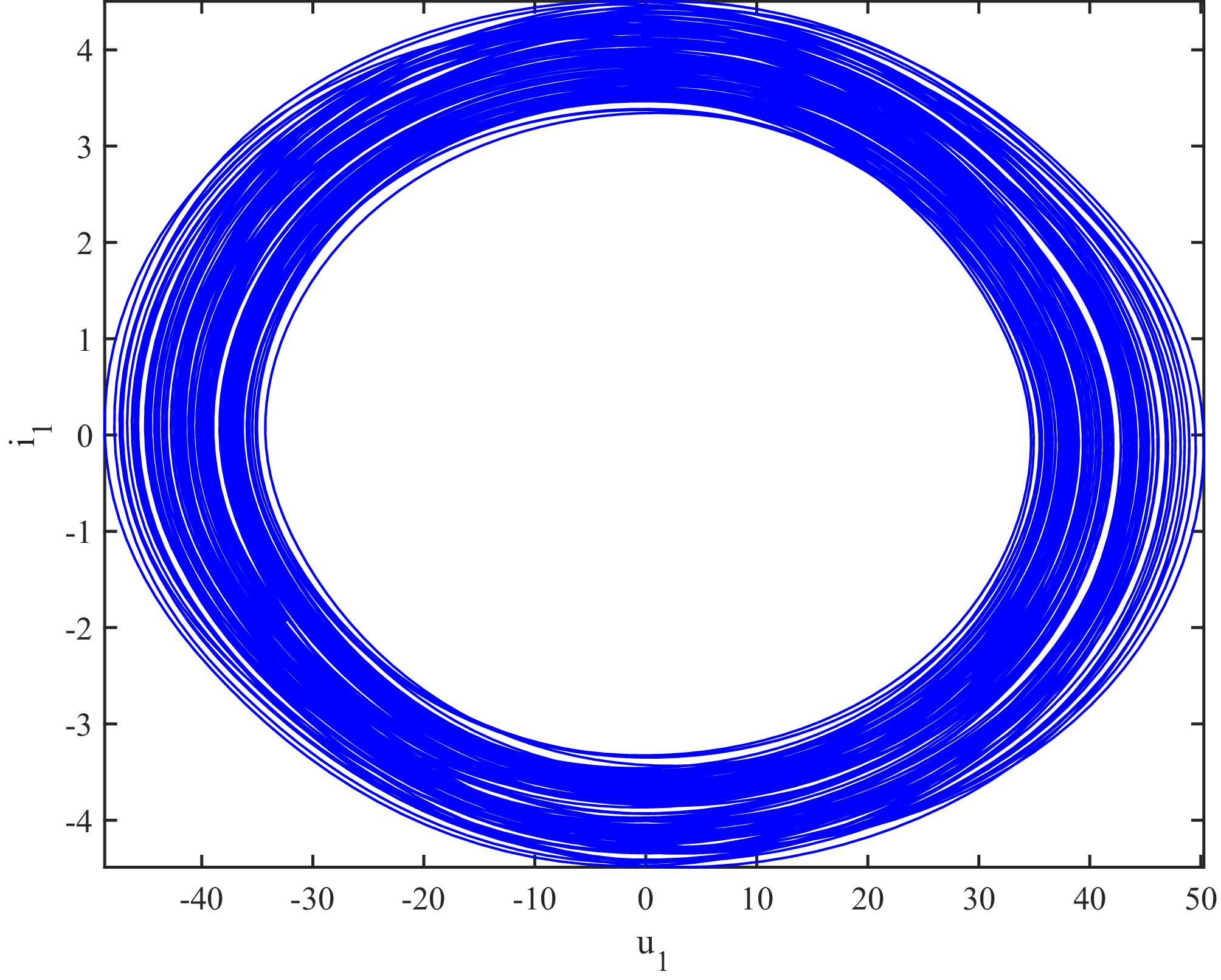
Figure 12.
Phase trajectory of subsystem 1.
-
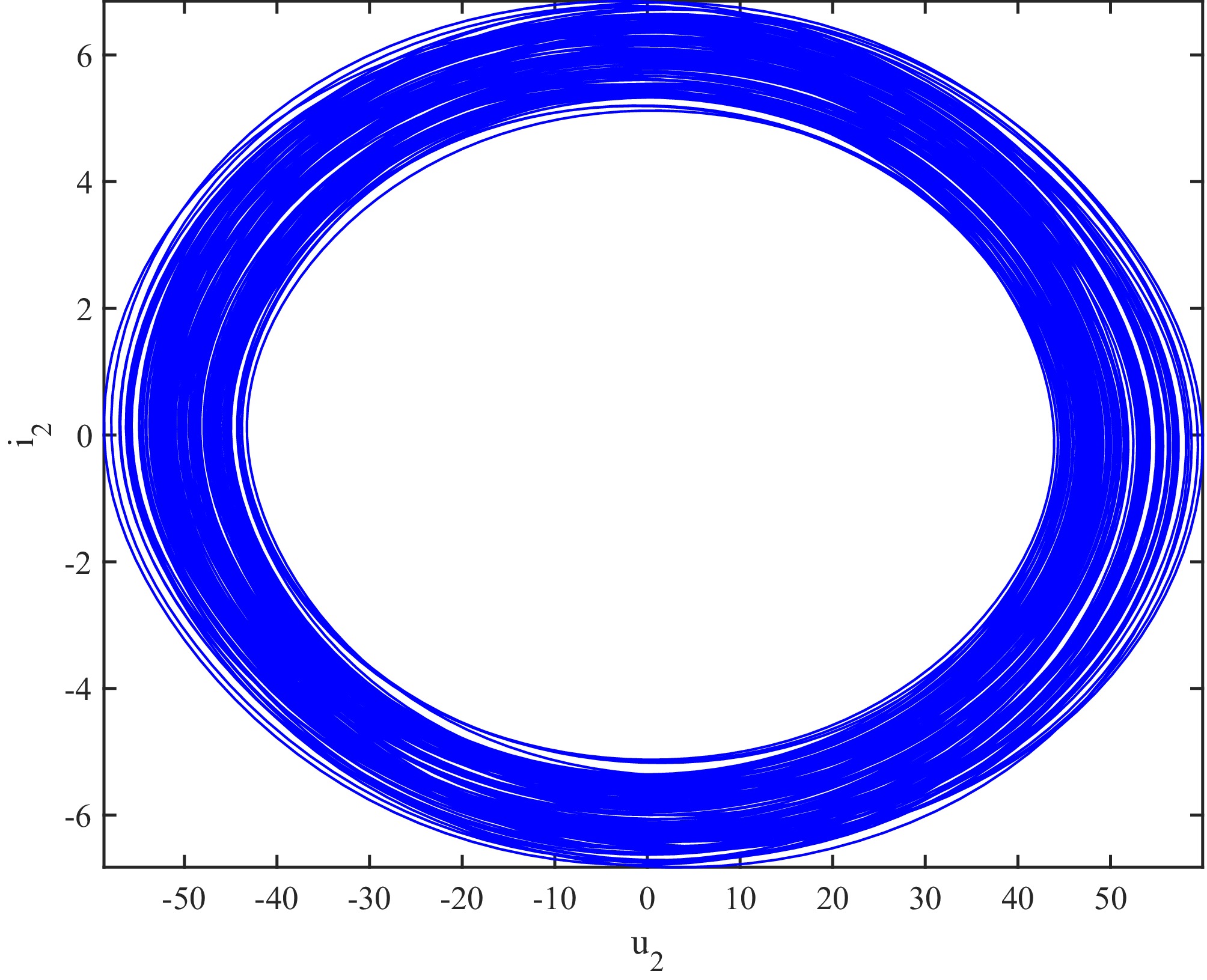
Figure 13.
Phase trajectory of subsystem 2.
-
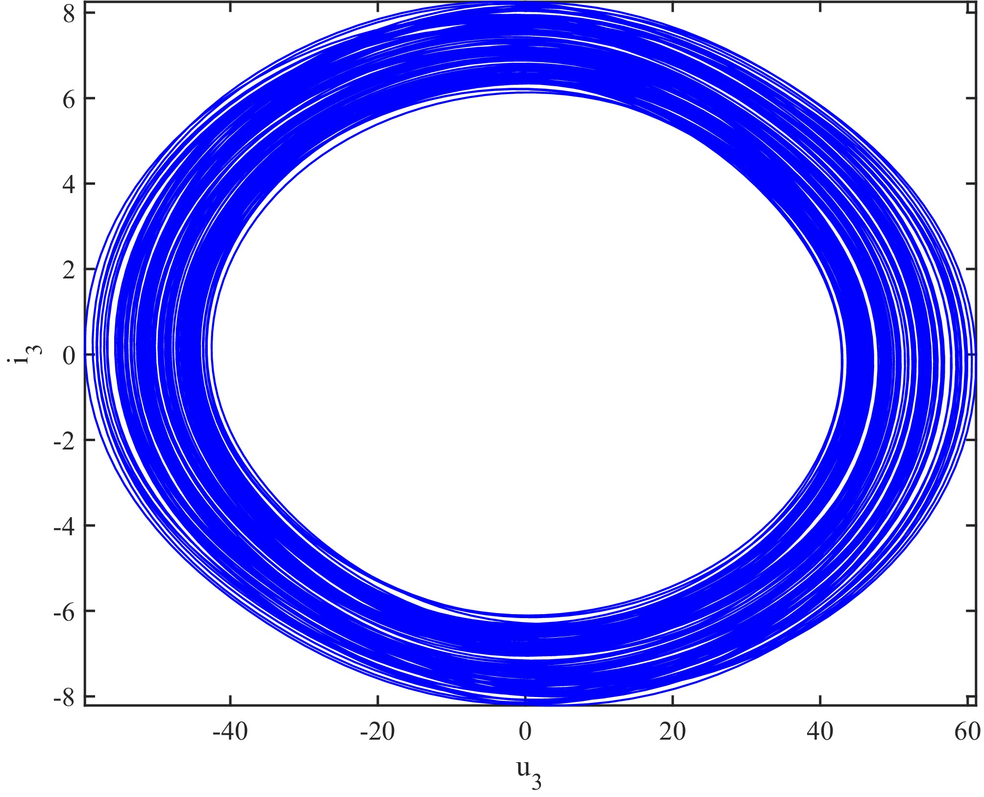
Figure 14.
Phase trajectory of subsystem 3.
-
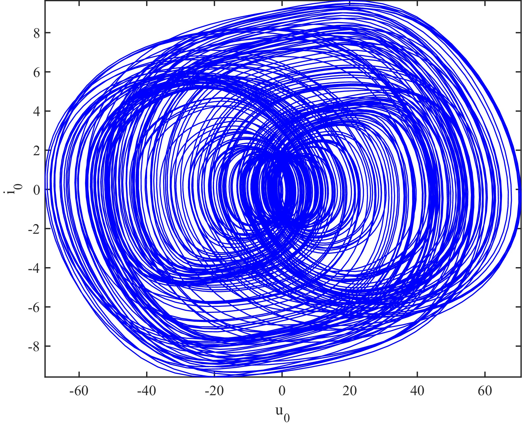
Figure 15.
Phase trajectory of the transmitter with mutual inductance variation.
-
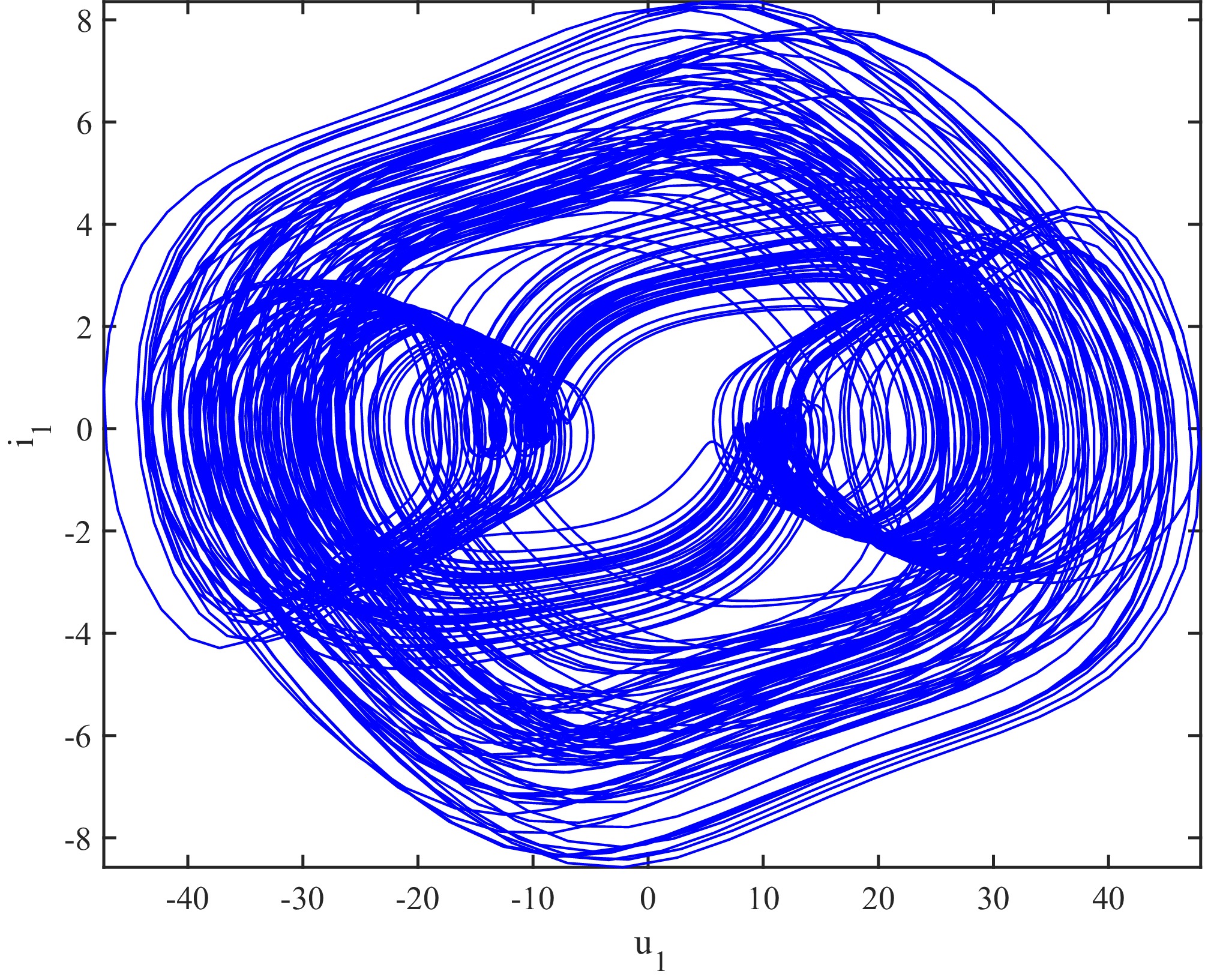
Figure 16.
Phase trajectory of receiver 1 with mutual inductance variation.
-
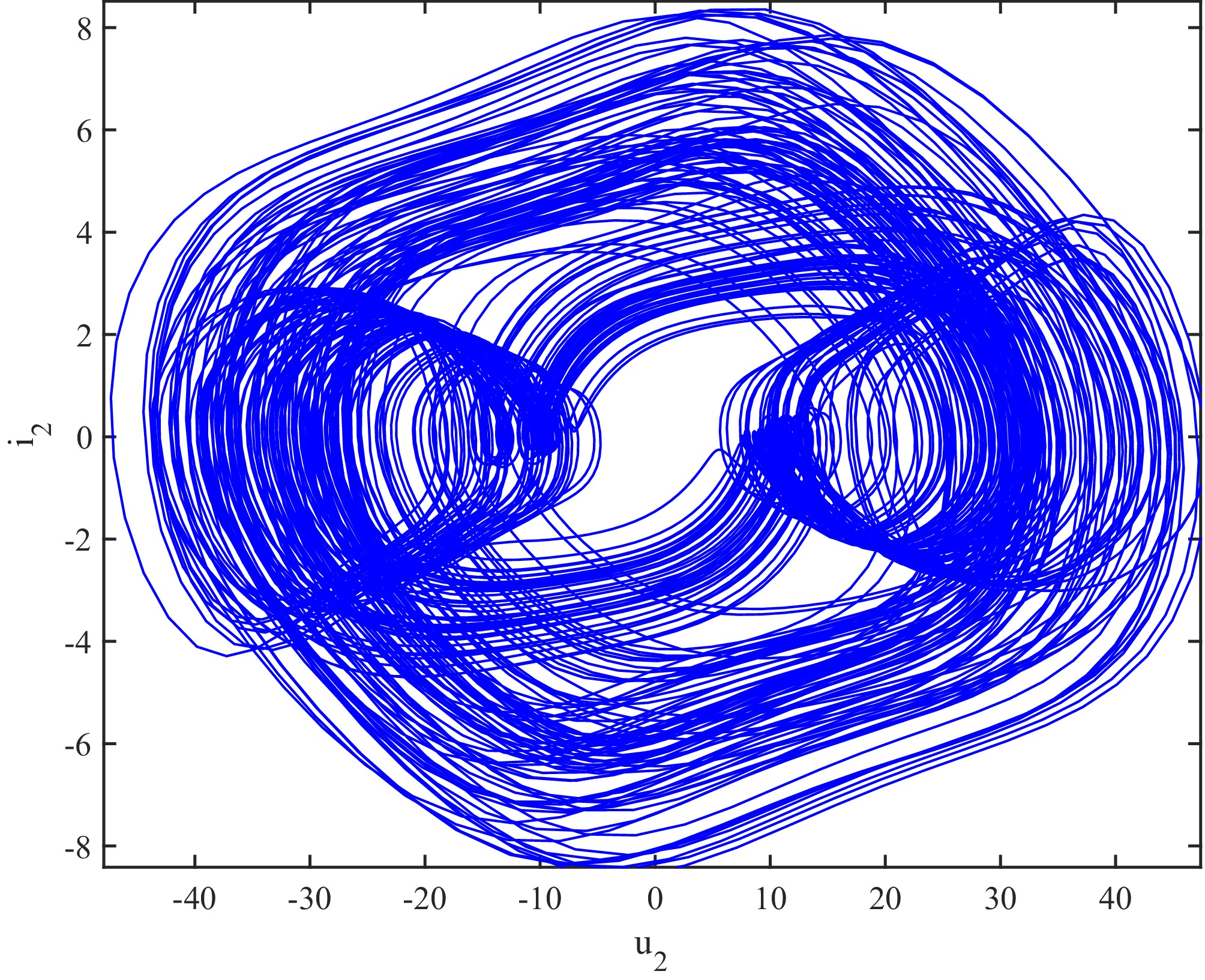
Figure 17.
Phase trajectory of receiver 2 with mutual inductance variation.
-
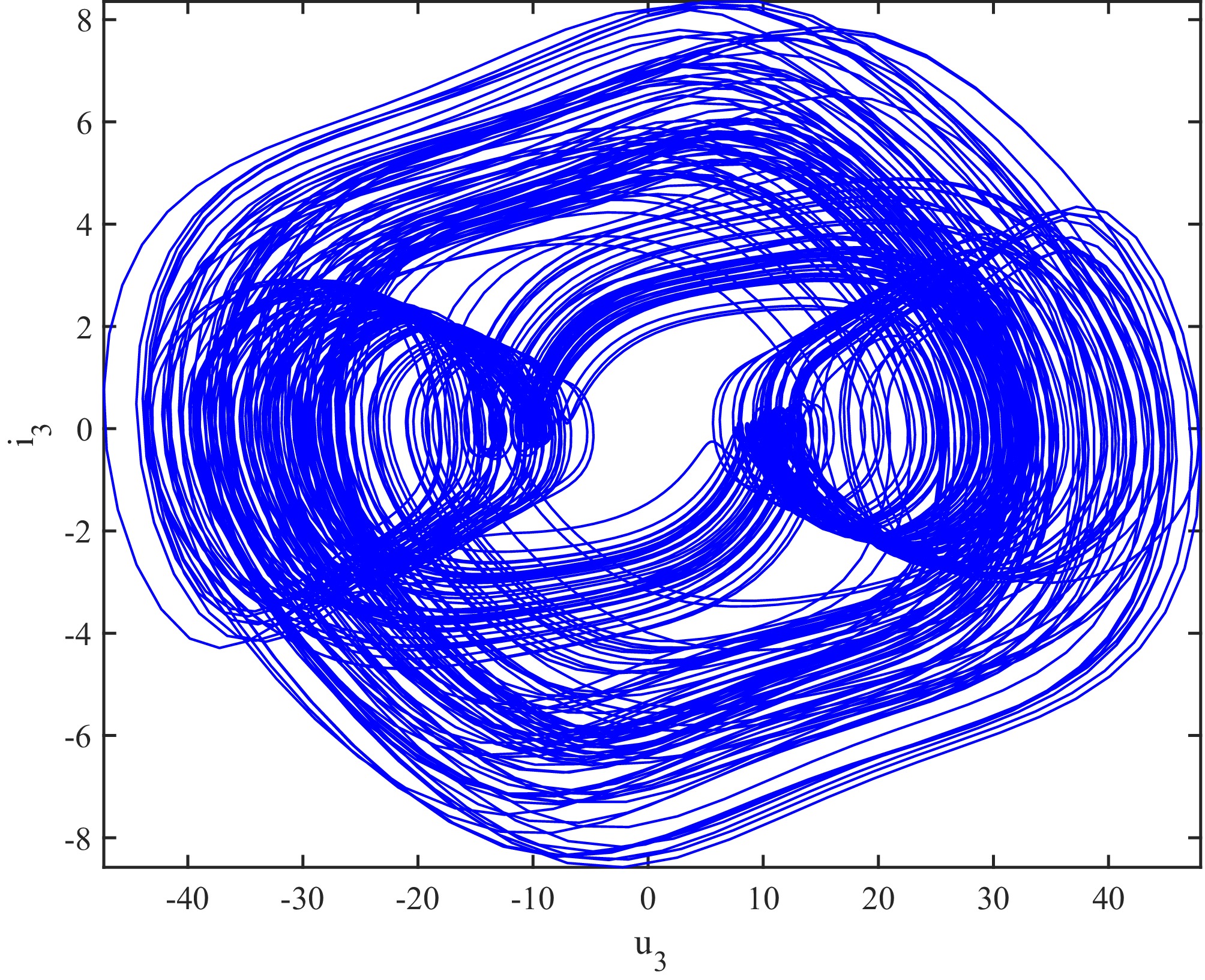
Figure 18.
Phase trajectory of receiver 3 with mutual inductance variation.
-
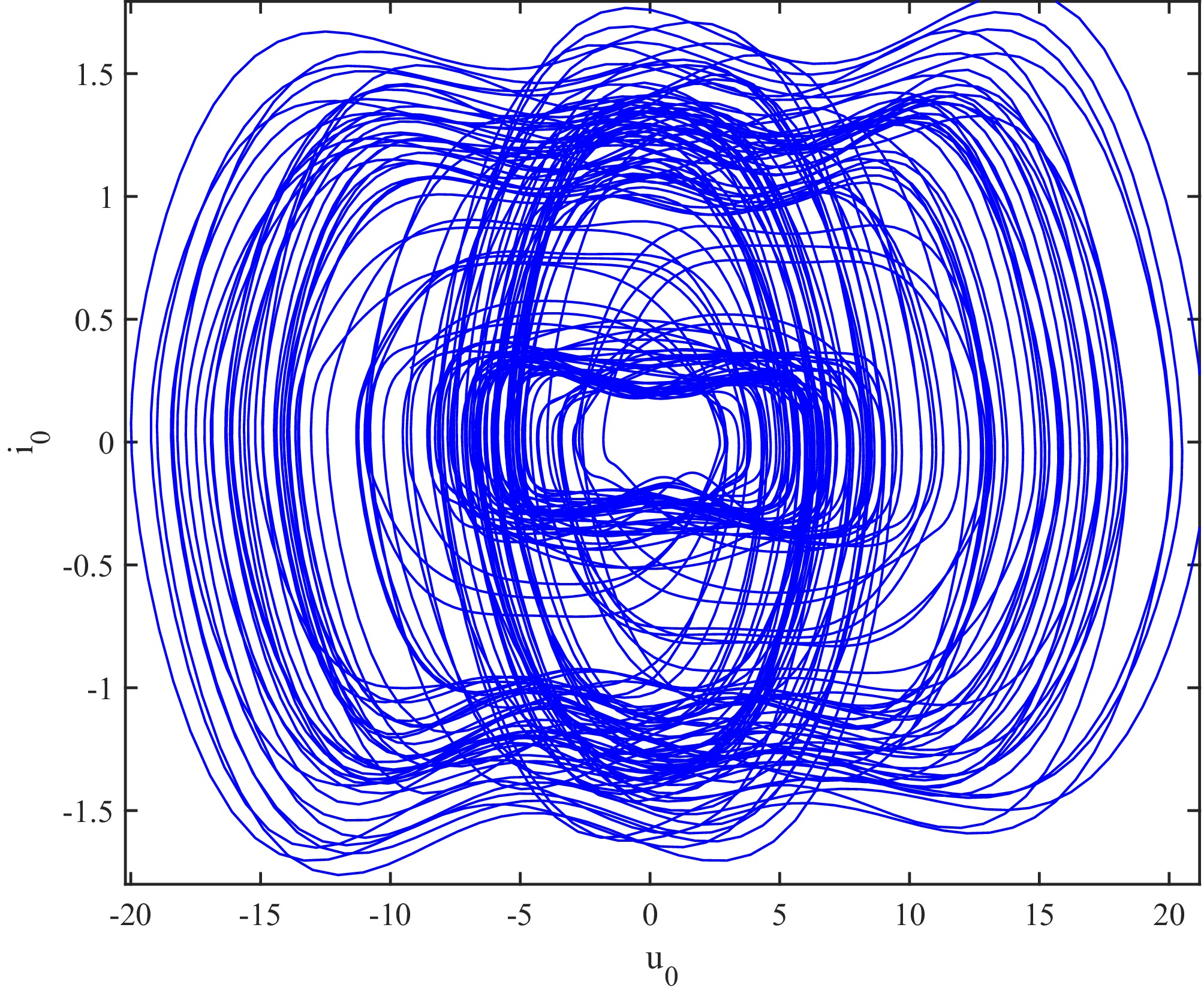
Figure 19.
Phase trajectory of the transmitter with load variation.
-
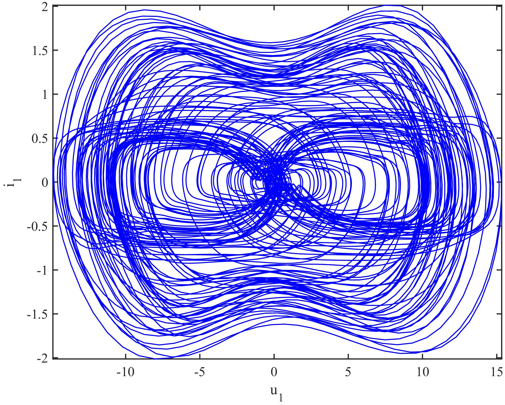
Figure 20.
Phase trajectory of receiver 1 with load variation.
-
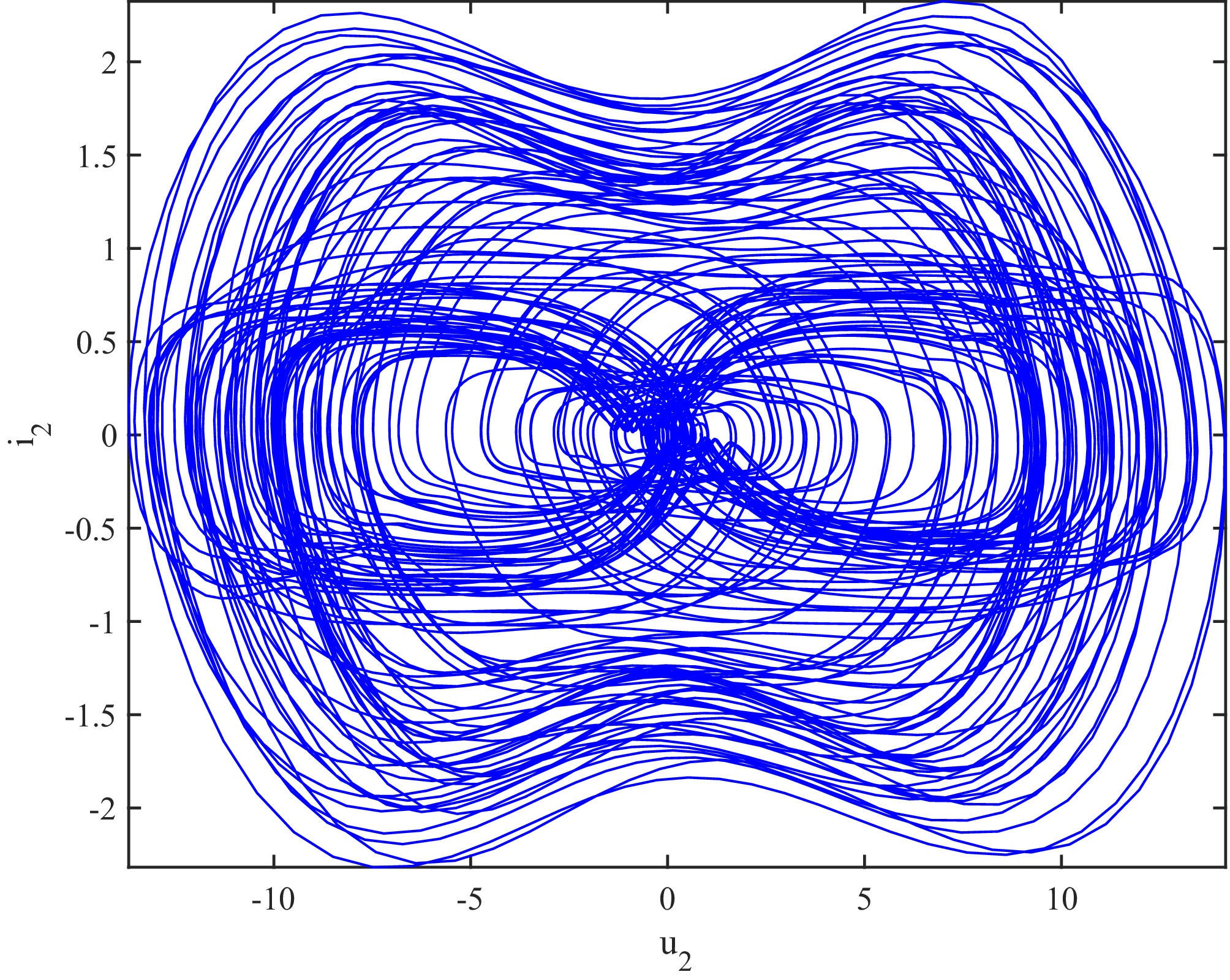
Figure 21.
Phase trajectory of receiver 2 with load variation.
-
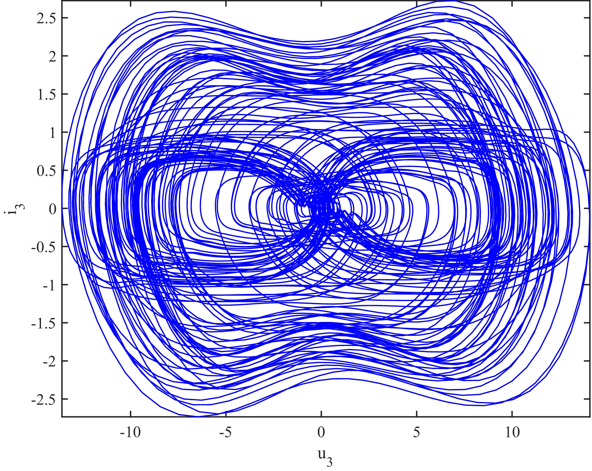
Figure 22.
Phase trajectory of receiver 3 with load variation.
Figures
(22)
Tables
(0)