-
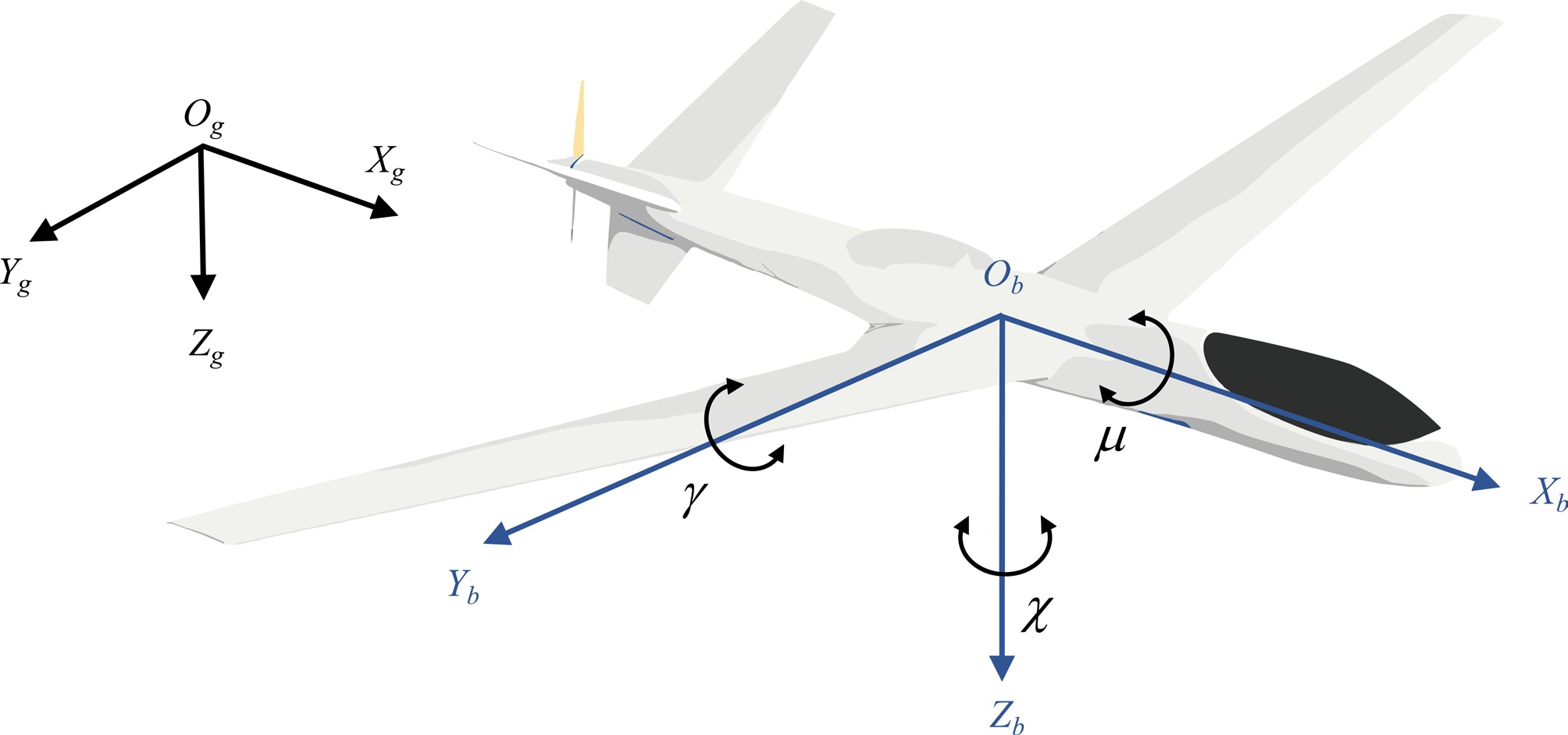
Figure 1.
The structure of fixed-wing UAV.
-
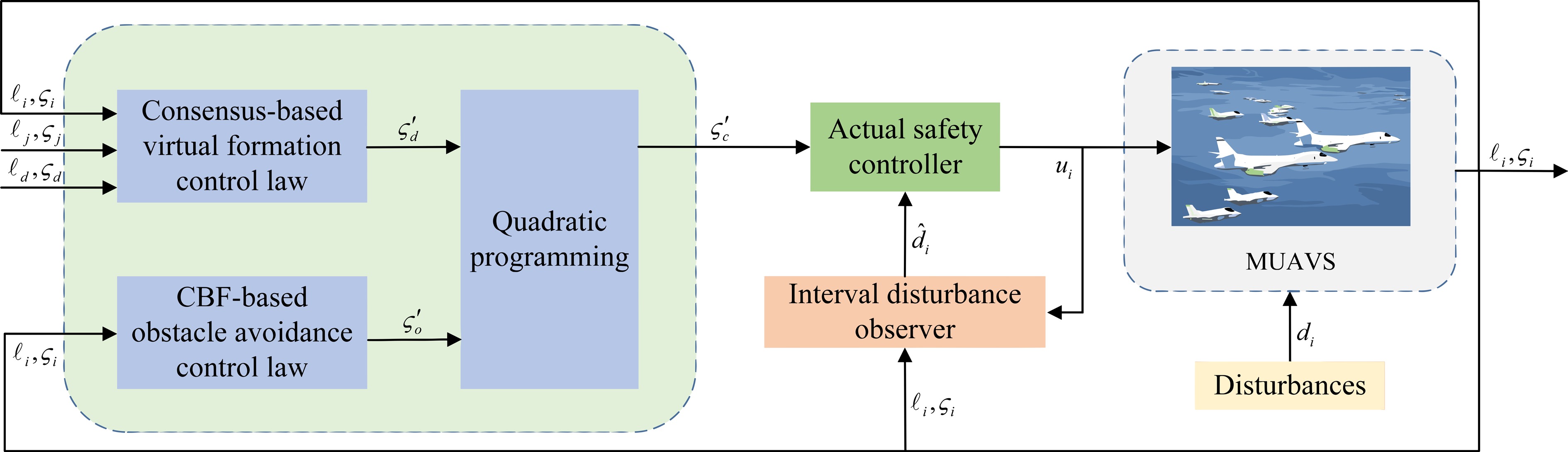
Figure 2.
Control flow block diagram of the proposed method.
-
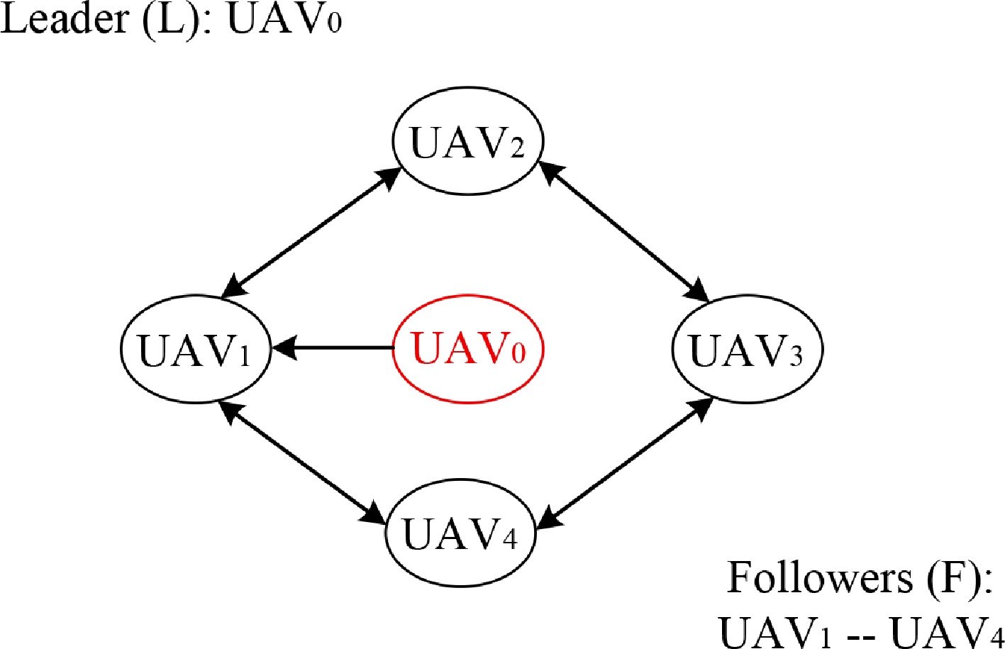
Figure 3.
MUAVS communication topology schematic diagram.
-
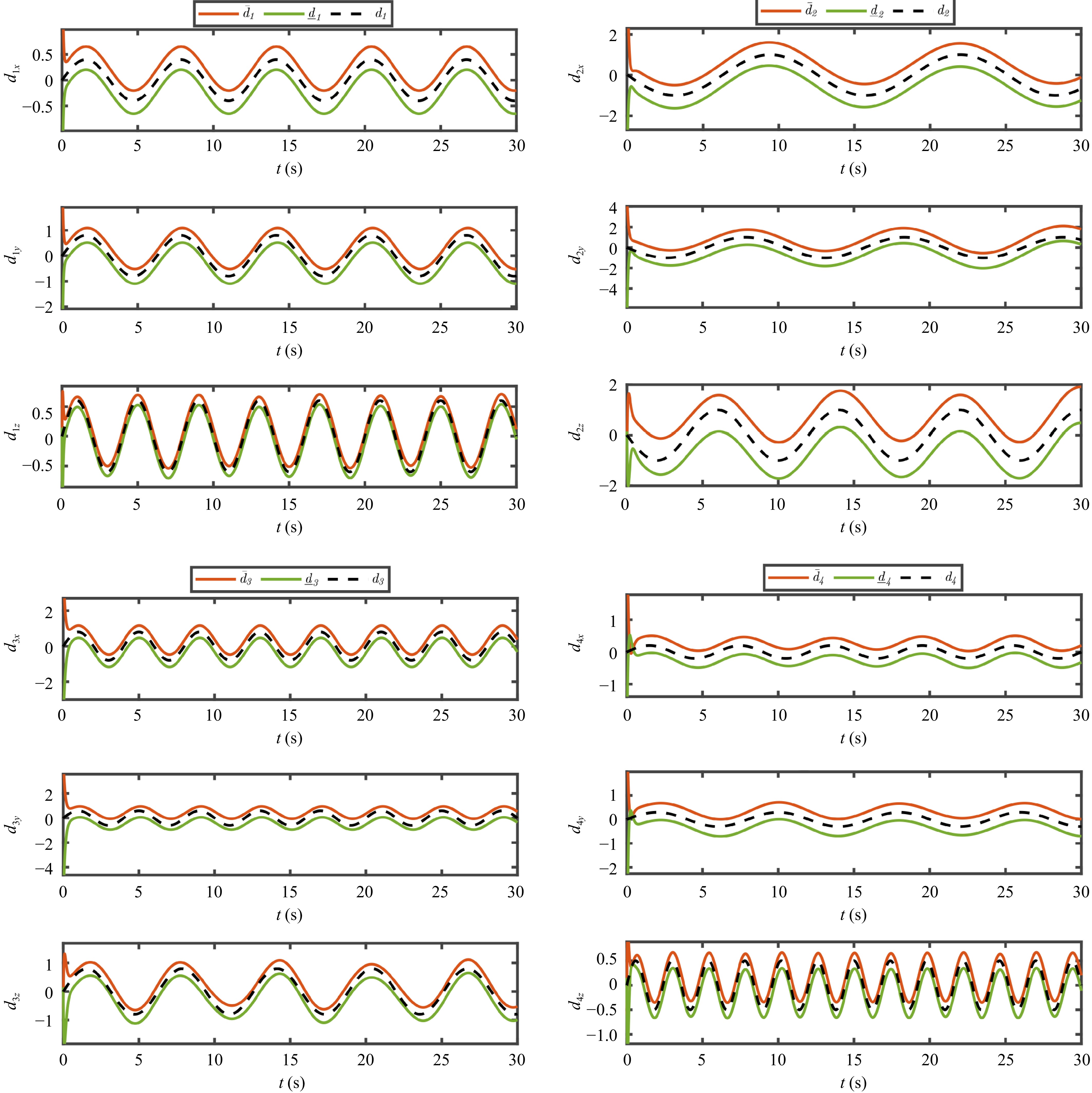
Figure 4.
Estimation results of unknown disturbance under the IDO.
-
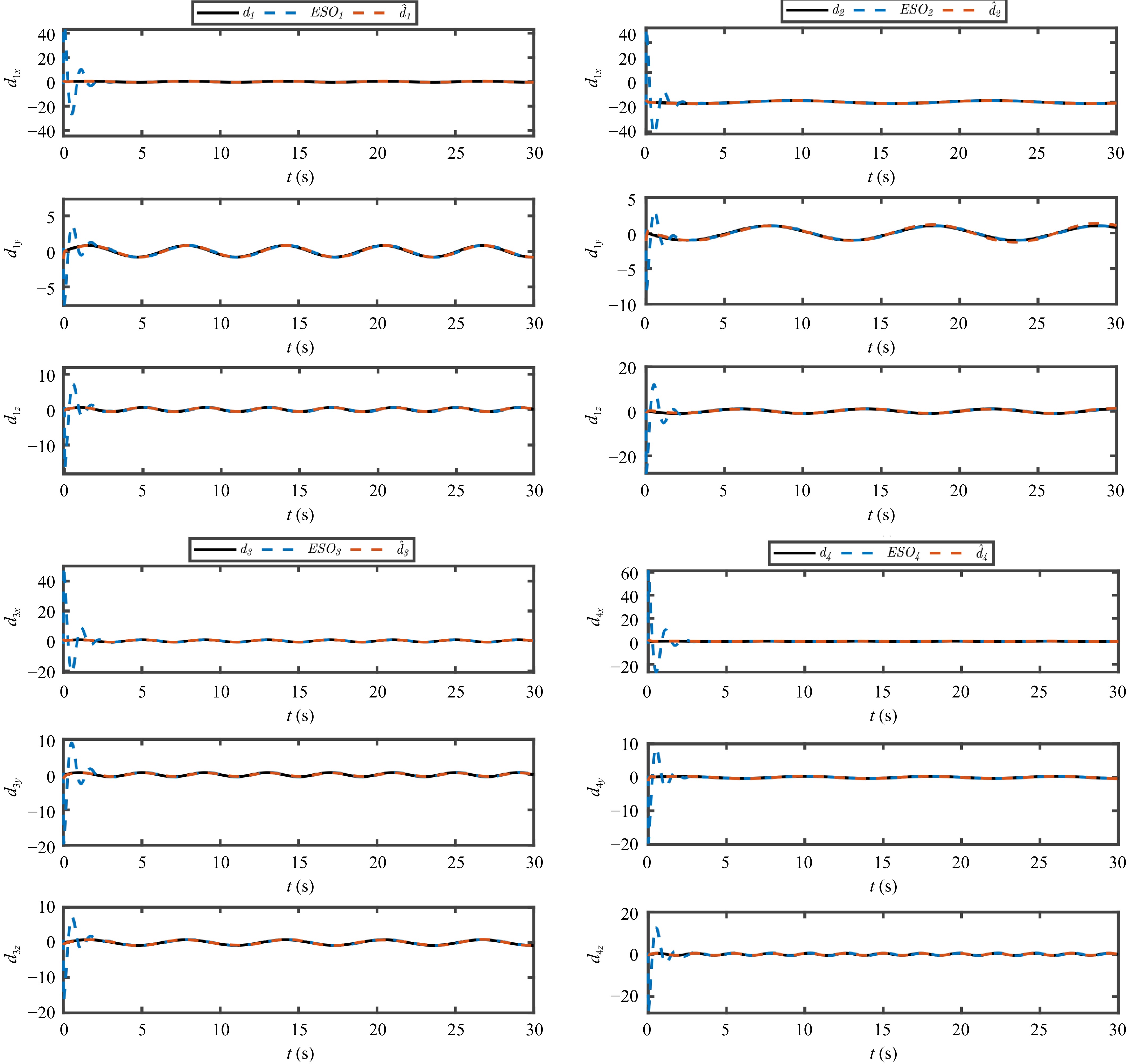
Figure 5.
Comparison of estimation results of unknown disturbance under the IDO and ESO.
-
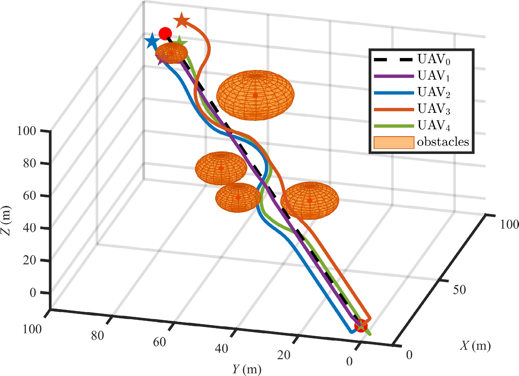
Figure 6.
3D diagram of APF-based rectangular formation obstacle avoidance.
-
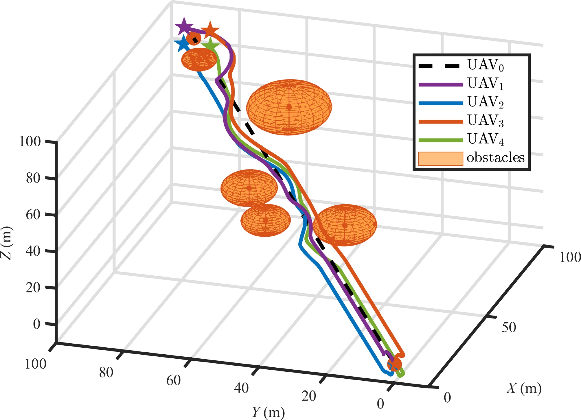
Figure 7.
3D diagram of CBF-based rectangular formation obstacle avoidance.
-
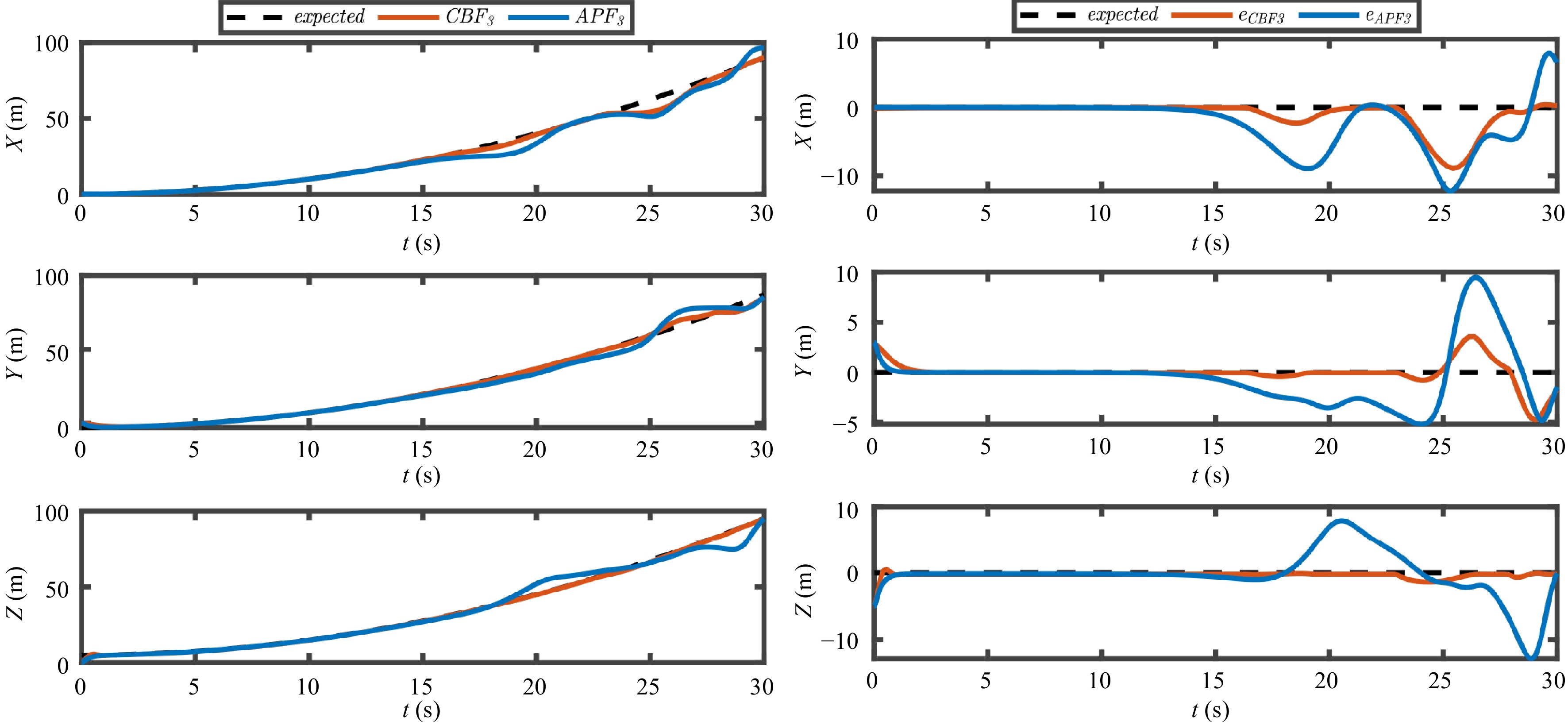
Figure 8.
Comparison tracking results and error for UAV3 under the CBF and APF.
-
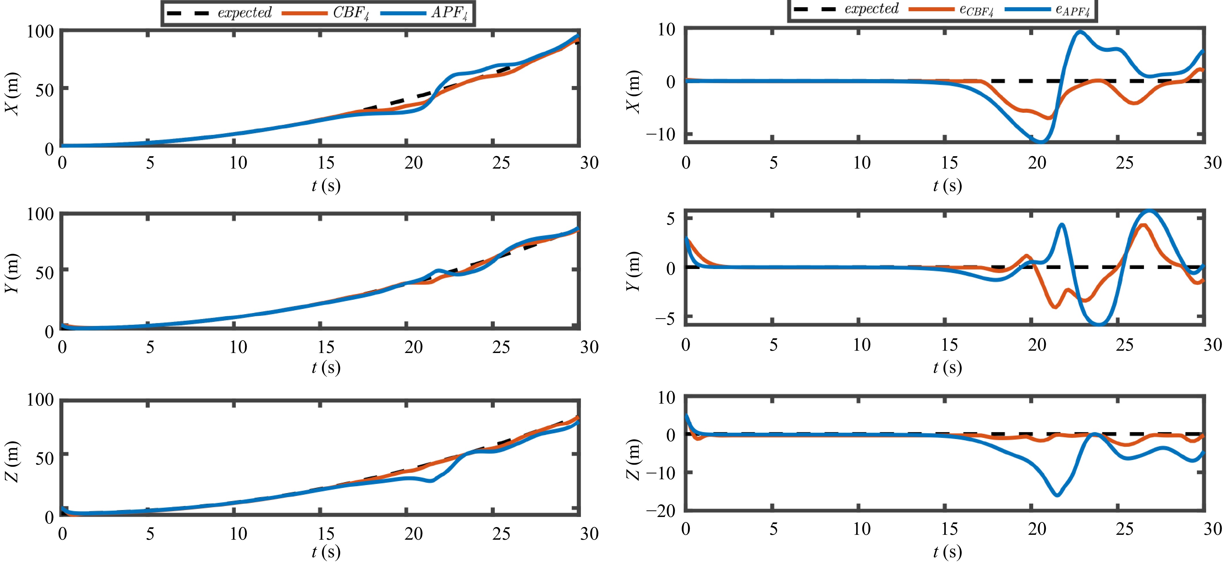
Figure 9.
Comparison tracking results and error for UAV4 under the CBF and APF.
-
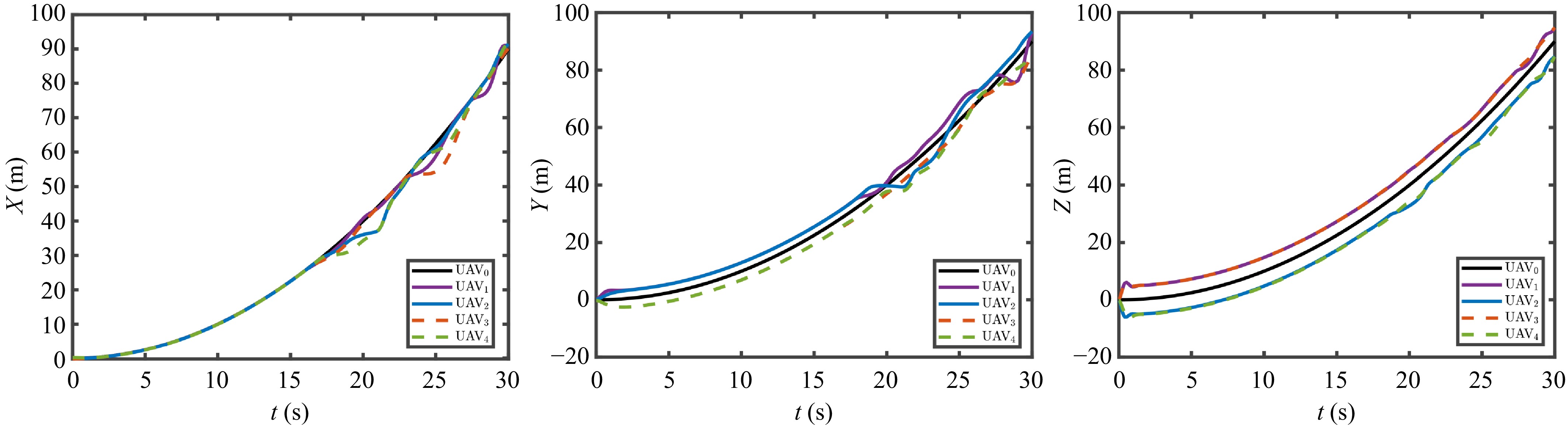
Figure 10.
Three-axis position tracking of UAV formation.
-
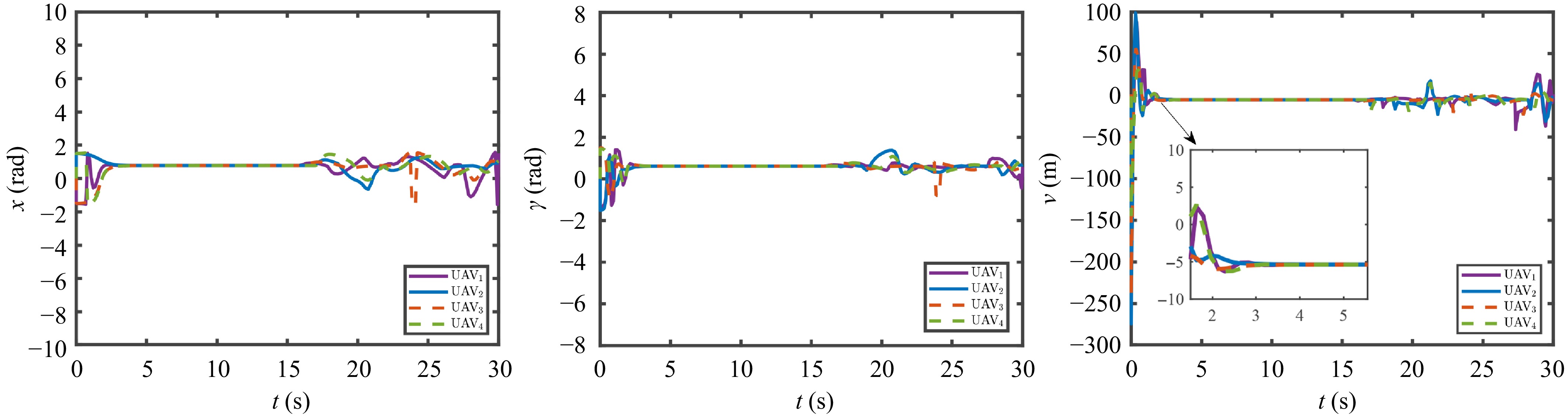
Figure 11.
Flight path angles and speed of the UAV formation.
-
Number X Y Z UAV1 0 3 5 UAV2 0 −3 5 UAV3 0 3 −5 UAV4 0 −3 −5 Table 1.
Relative position between UAV
$ _i $ $ _0 $ -
Number Obstacle position Obstacle radius Obstacle1 (30, 50, 41) 7 Obstacle2 (45, 30, 35) 9 Obstacle3 (50, 60, 45) 8 Obstacle4 (70, 55, 75) 12 Obstacle5 (80, 83, 85) 5 Table 2.
Parameter setting of the obstacles.
-
Method $ {e_{3x}} $ $ {e_{3y}} $ $ {e_{3z}} $ $ {e_{4x}} $ $ {e_{4y}} $ $ {e_{4z}} $ CBF 1.00 3.19 4.71 3.07 4.40 5.74 APF 4.15 6.23 8.41 2.74 3.73 11.92 Table 3.
Average MAE of three-axis position.
-
Method $ {e_{3x}} $ $ {e_{3y}} $ $ {e_{3z}} $ $ {e_{4x}} $ $ {e_{4y}} $ $ {e_{4z}} $ CBF 1.40 3.19 4.71 3.89 4.67 5.76 APF 5.29 6.27 8.89 7.69 4.54 12.81 Table 4.
Average RMSE of three-axis position.
Figures
(11)
Tables
(4)