-
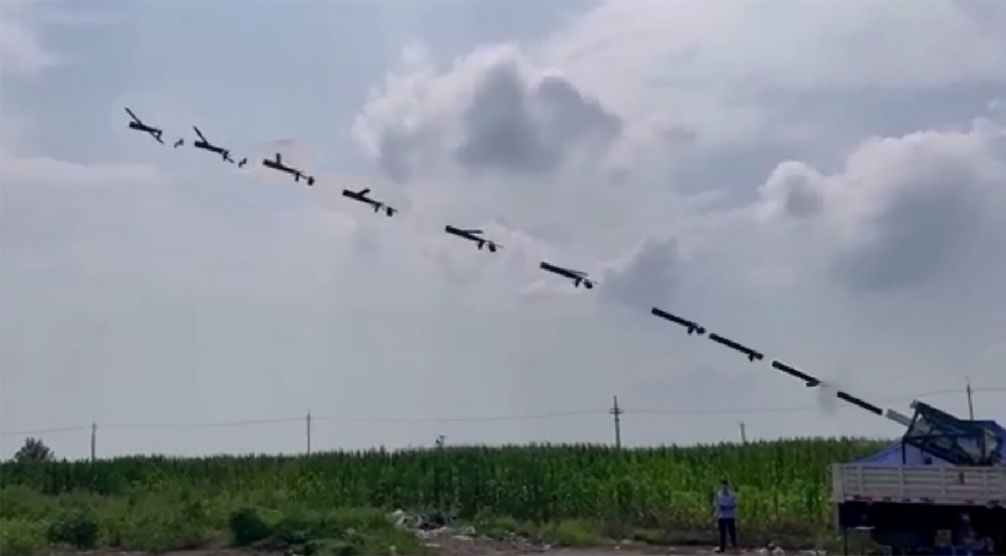
Figure 1.
Flight experiment of the launch process of this paper.
-
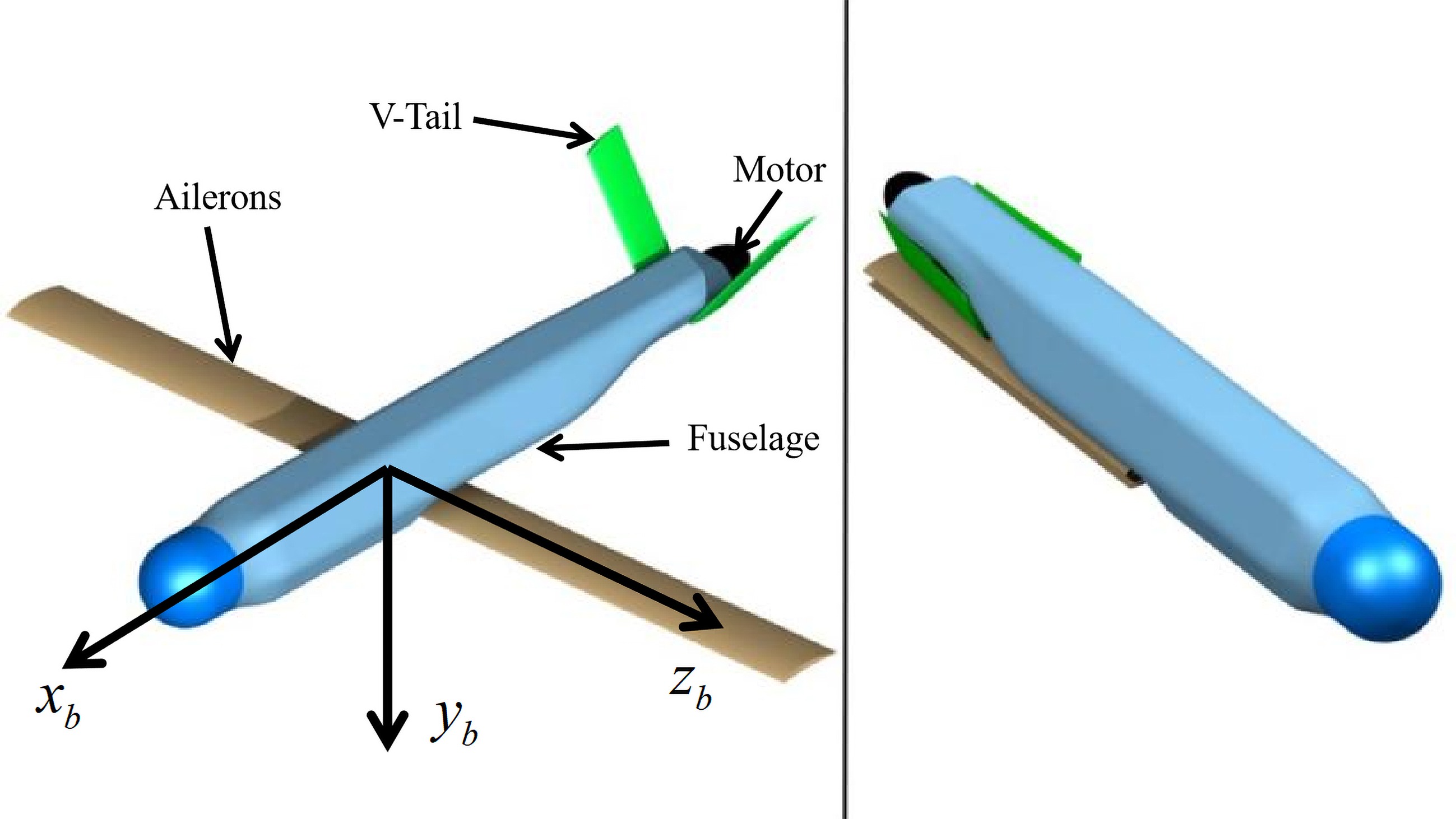
Figure 2.
The layouts of small variable-geometry UAV: left side, wings unfolded; right side, wings folded.
-
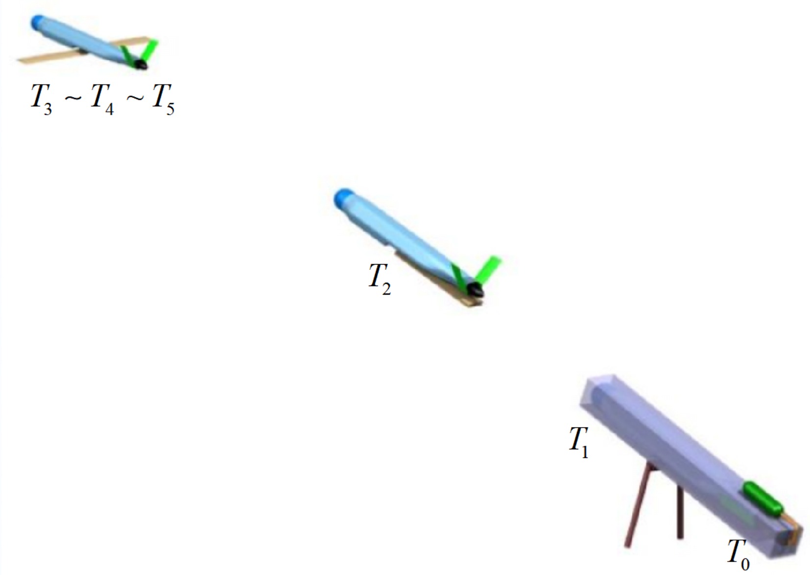
Figure 3.
Animation of launch process.
-
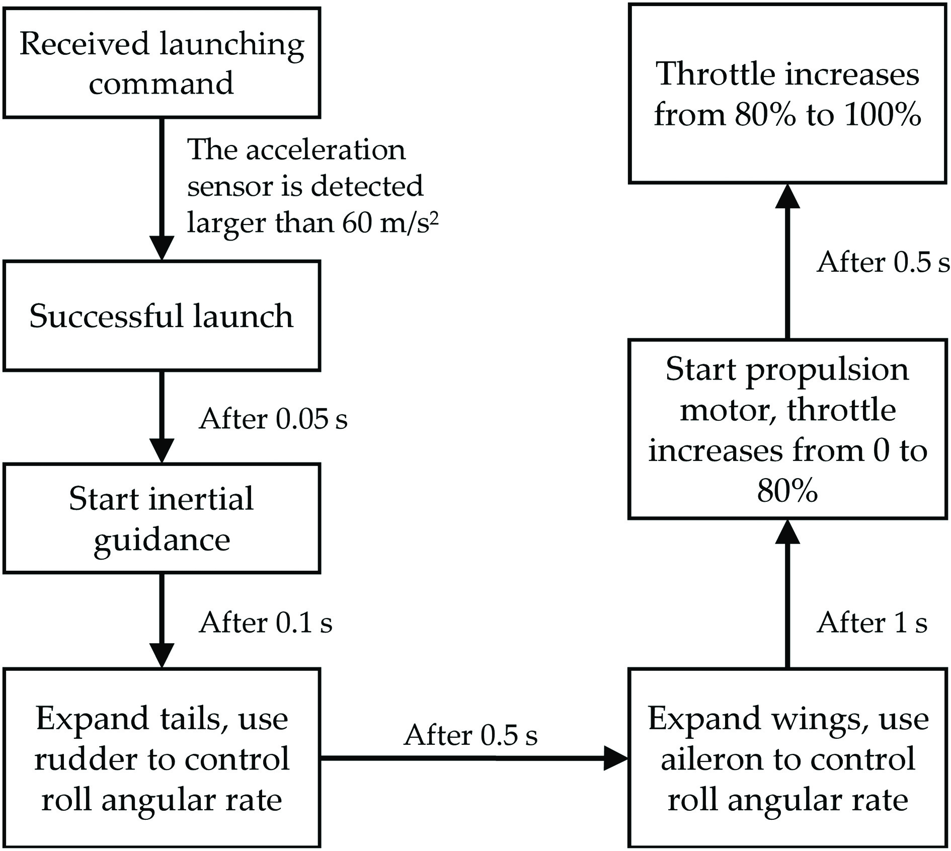
Figure 4.
Control strategy for the launch process. High-pressure gas firstly pushes the UAV out of the launcher, and then the wings and V-tails deploy and the propulsion motor is activated.
-
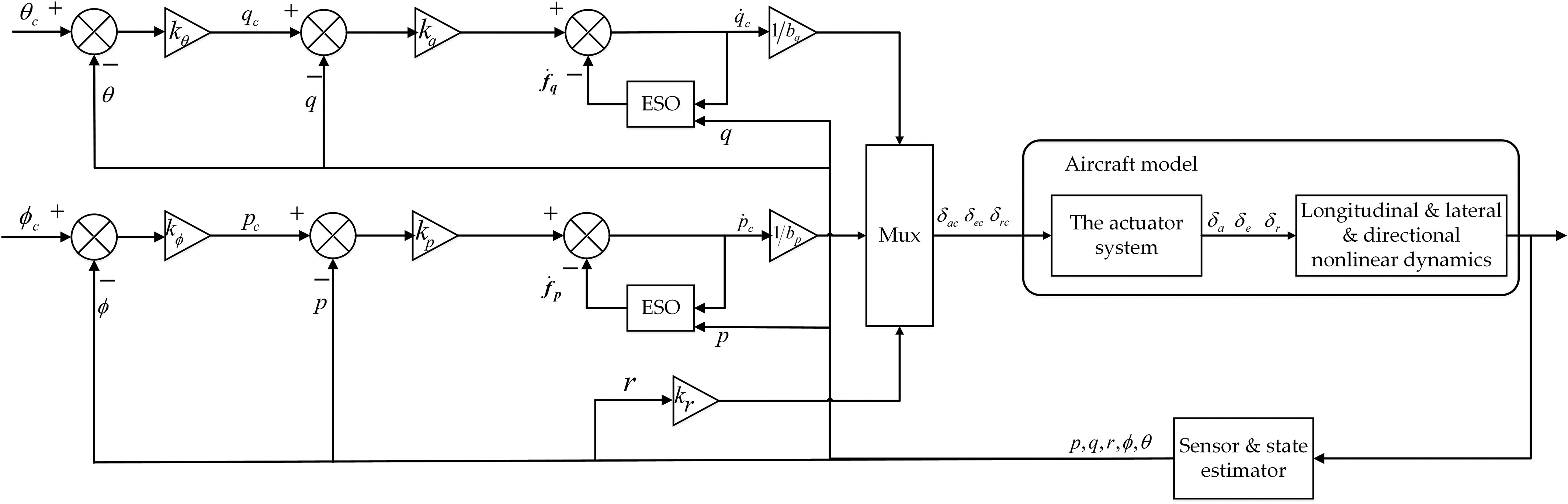
Figure 5.
Complete control architecture. Pitch and roll cascaded ESO-based control schemes to handle the control stabilization.
-
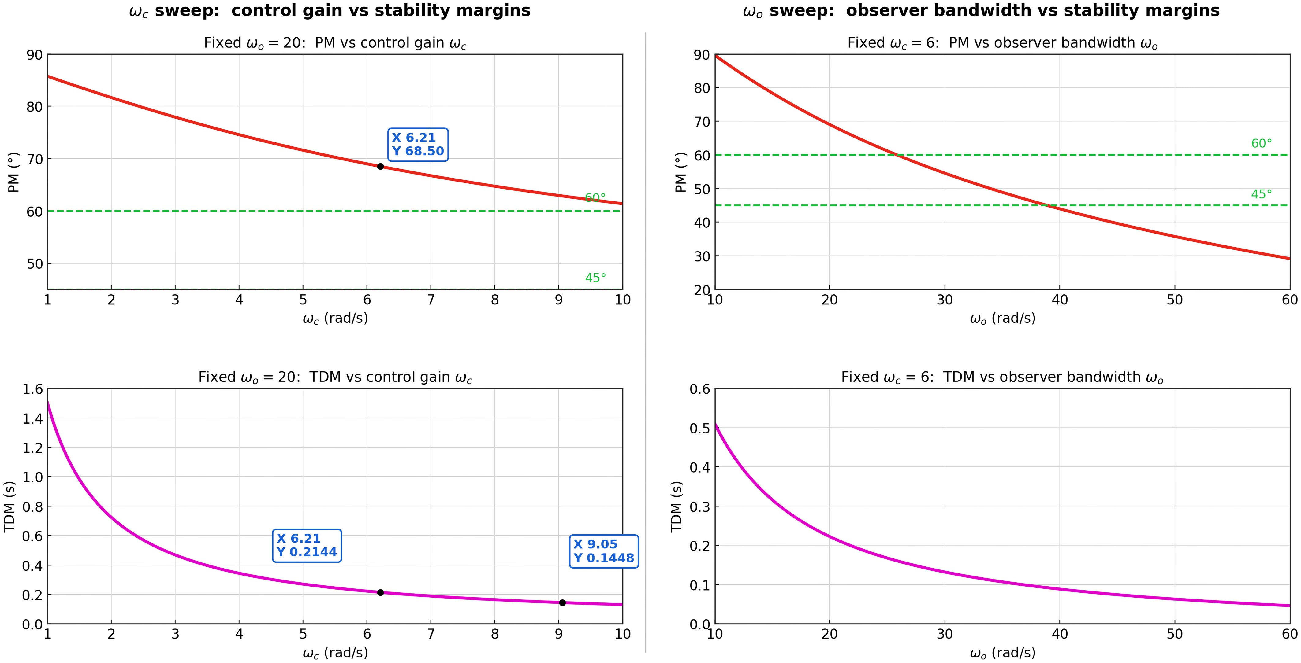
Figure 6.
Simulation verification of stability margins. Left: control-gain sweep (
$ \omega_c $ $ \omega_o $ $ \omega_o $ $ \omega_c $ -
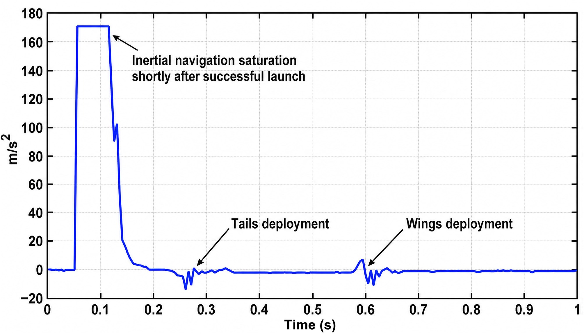
Figure 7.
The evolution of acceleration vs time throughout the whole launch process.
-
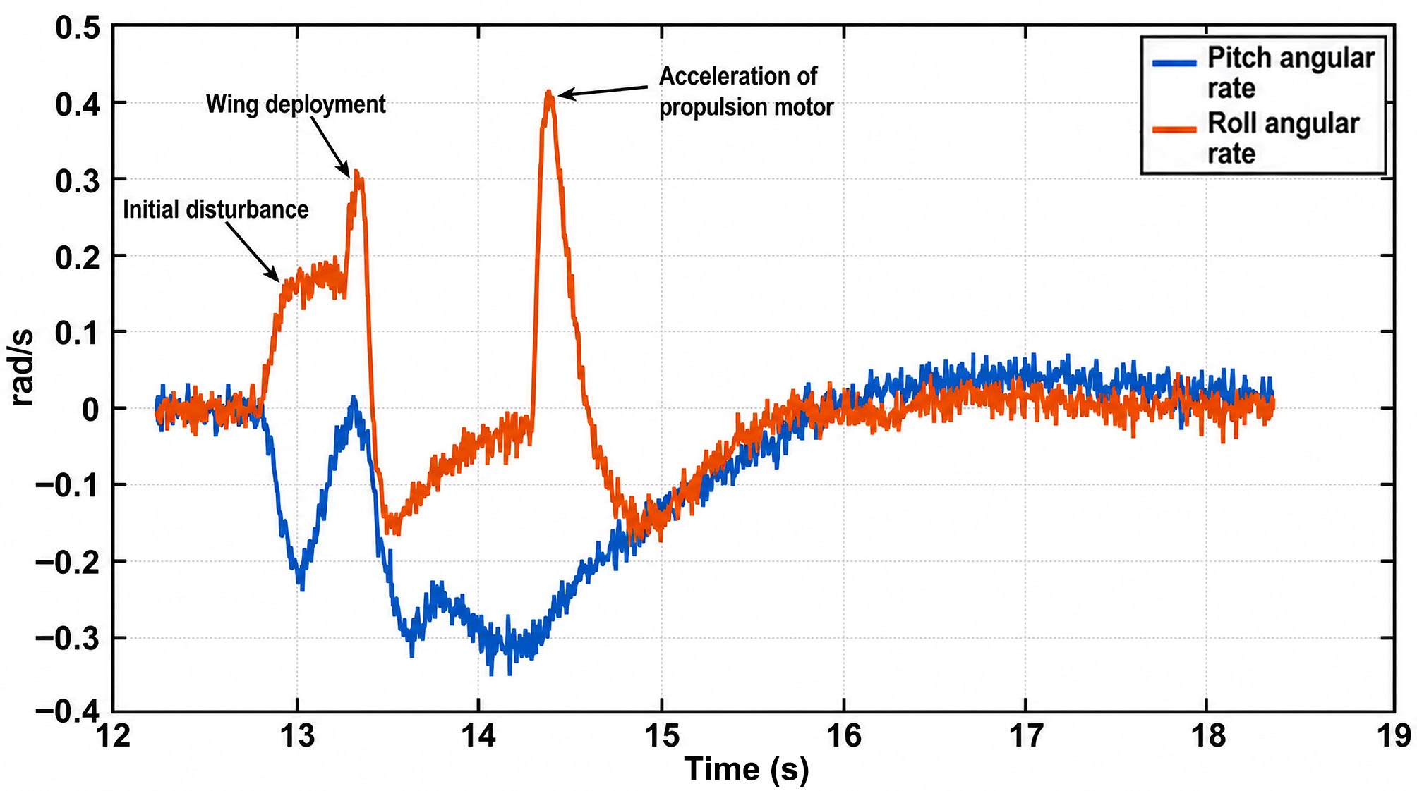
Figure 8.
Time histories of the roll angular rate without adopting segmental throttle control strategy.
-
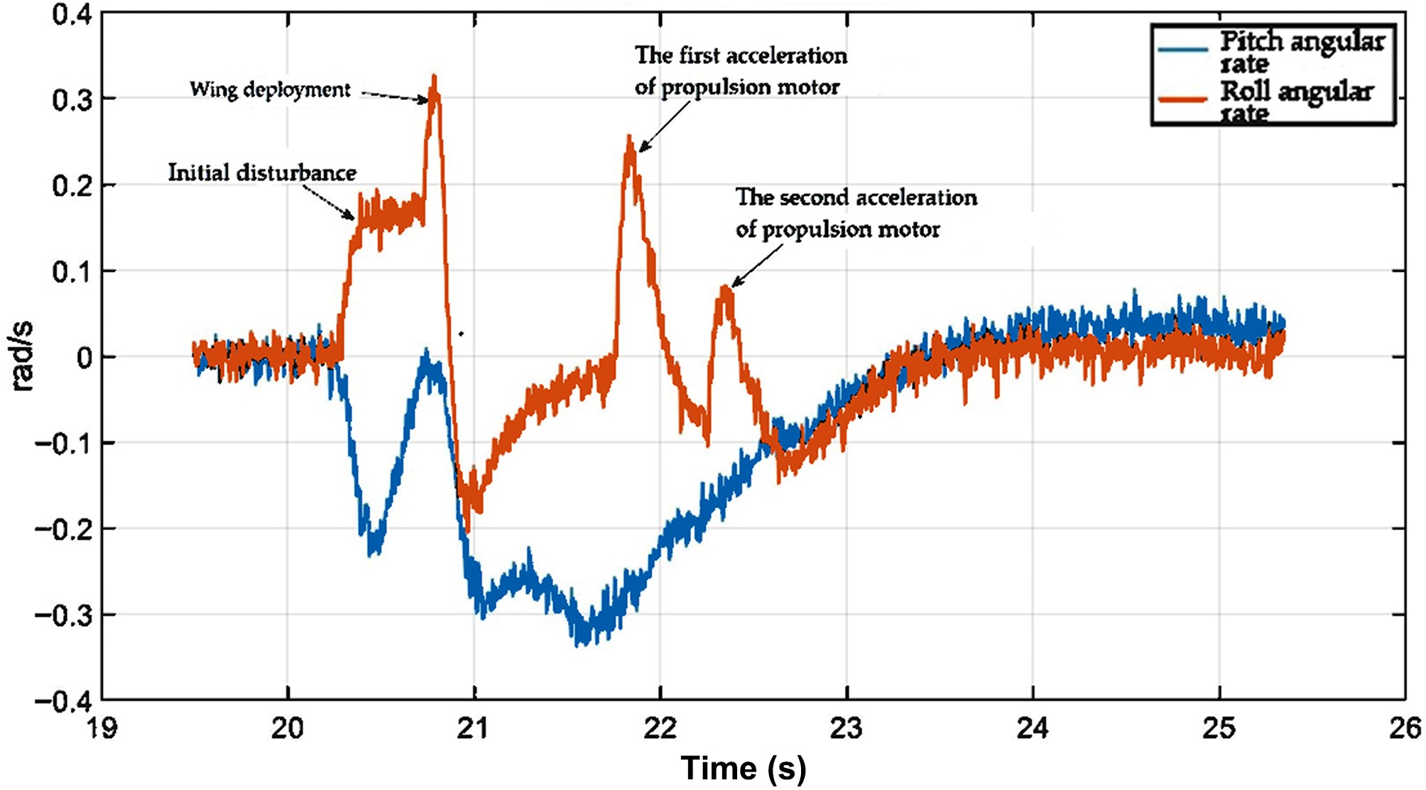
Figure 9.
Time histories of the roll angular rate adopting the segmental throttle control strategy.
-
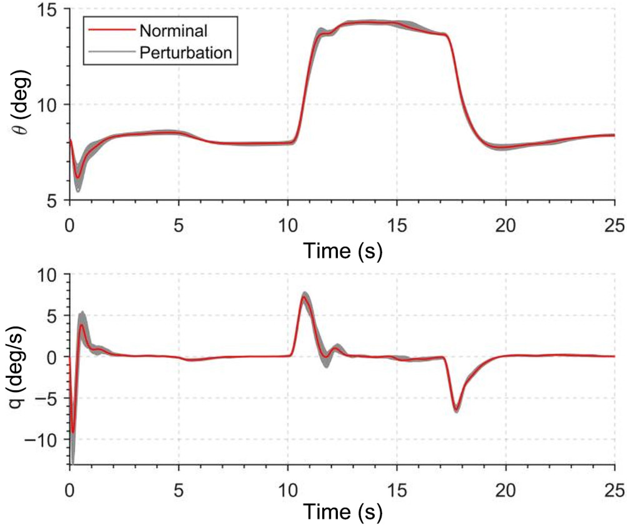
Figure 10.
Results of Monte Carlo simulations of the ESO-based pitch control.
-
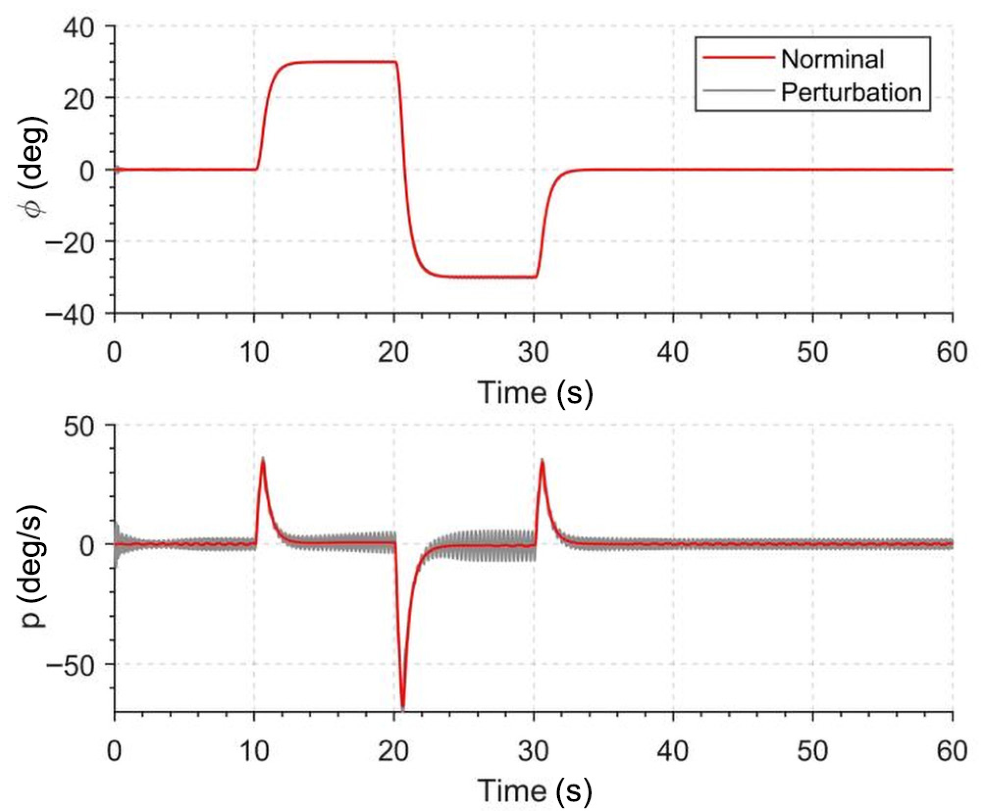
Figure 11.
Results of Monte Carlo simulations of the ESO-based roll control.
-
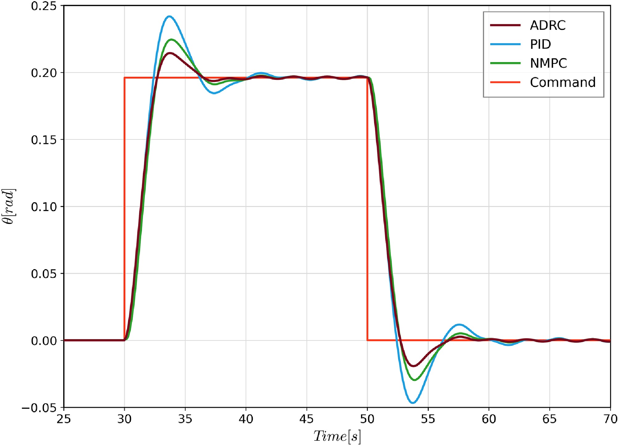
Figure 12.
The pitch angle tracking performance comparison among ADRC, PID, and NMPC.
-
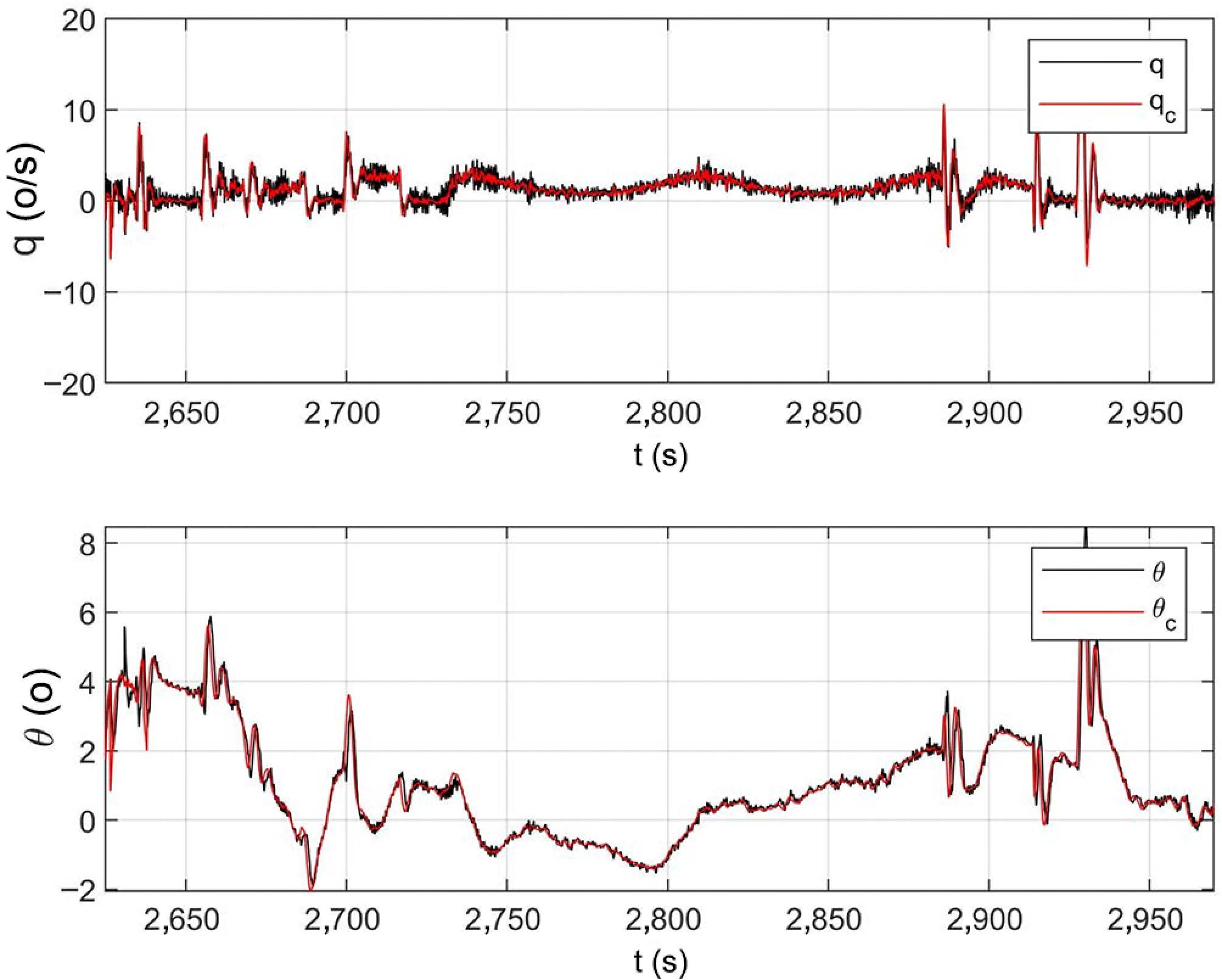
Figure 13.
Time histories of the pitch channel.
-
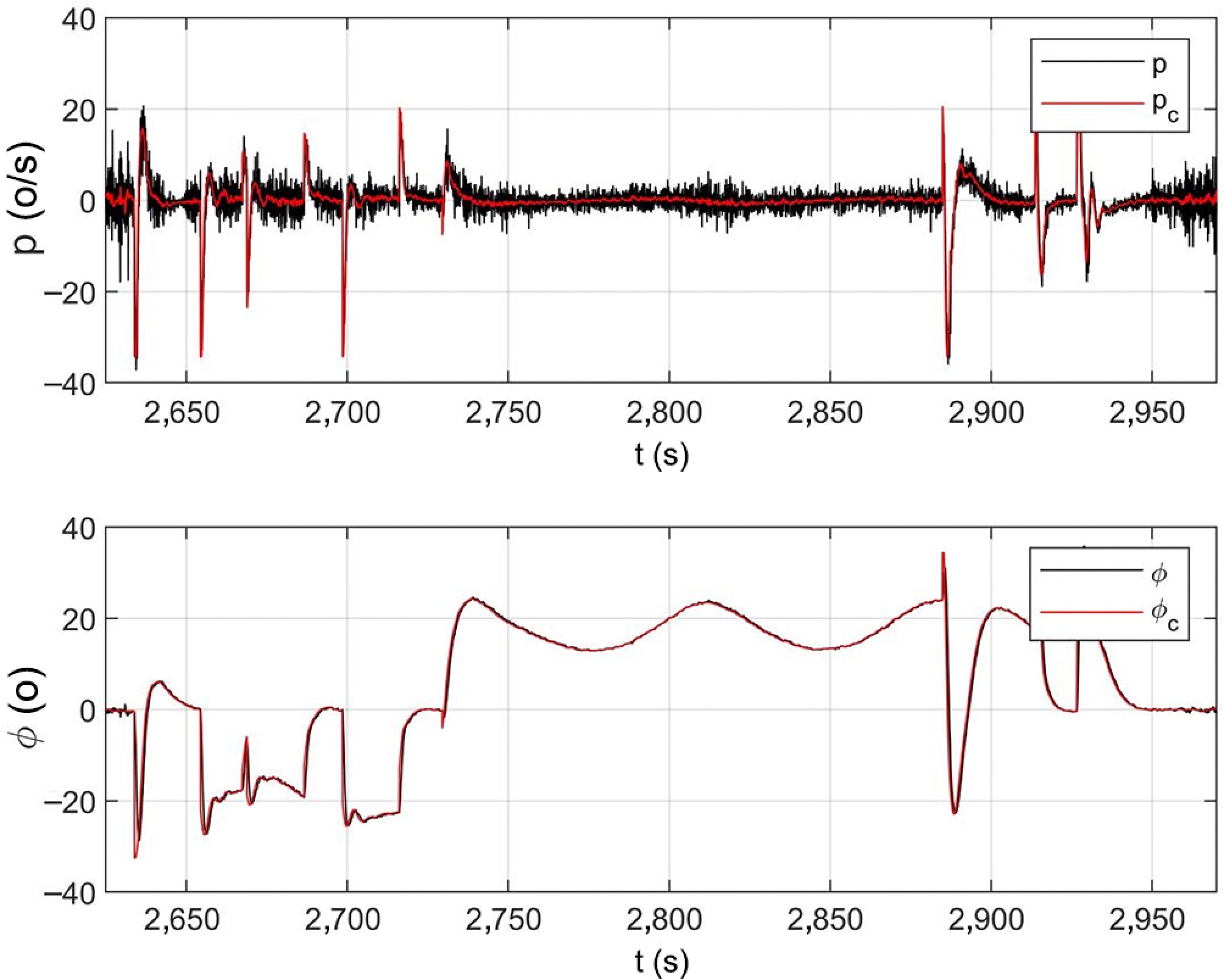
Figure 14.
Time histories of the roll channel.
-
Actuator Natural
frequency (Hz)Damping
ratioPosition
limitation (°)Position rate
limitation (°/s)Aileron 8 0.8 ± 25 ± 100 Elevator 8 0.8 ± 25 ± 100 Rudder 8 0.8 ± 25 ± 100 Table 1.
Characteristics of the actuators.
-
Parameter Value ESO fal function, $ \alpha $ 0.5 ESO fal function, $ \delta $ 0.01 Pitch angular rate ESO gain, $ \beta_{1q} $ 20 Pitch angular rate ESO gain, $ \beta_{2q} $ 100 Roll angular rate ESO gain, $ \beta_{1p} $ 20 Roll angular rate ESO gain, $ \beta_{2p} $ 100 Bandwidth of pitch inner-loop, $ k_q $ 6 Bandwidth of roll inner-loop, $ k_p $ 10 Bandwidth of pitch outer-loop, $ k_{\theta} $ 1.5 Bandwidth of roll outer-loop, $ k_{\phi} $ 2 Table 2.
ESO-related control parameters.
-
Operating point GM (dB)* PM TDM (ms) Level 1/margin spec $ \omega_c $ $ \omega_o $ ≥ 6 68.5° 214 Adopted design point—met $ \omega_o $ – = 45° ≈ 90 Observer-bandwidth ceiling $ \omega_o $ – < 45° < 90 Over-fast observer: margins eroded * The gain margin (GM) at the adopted design point is specified by design to be ≥ 6 dB. Table 3.
Stability margins at the design operating points (from the sweeps of Fig. 6).
-
Parameter Uncertainty (%) Inertial parameters ± 30 Control coefficients ± 20 Aerodynamic coefficients ± 40 Engine thrust ± 10 Table 4.
Parameter perturbations in Monte Carlo simulations.
-
Method Value ADRC 1.5 PID 3.9 NMPC 2.4 Table 5.
Tracking errors of different control methods.
Figures
(14)
Tables
(5)