


-
After the Second Industrial Revolution, humanity entered the electrical age, marking the beginning of the large-scale utilization of electrical energy. With the development of the power system, people can use at least two cables to form a loop to efficiently obtain electric energy from the power system within a certain range. Thus far, the transmission mode of two cables still dominates in practice. However, there are some inevitable shortcomings in the practical application of the power transmission mode of two cables.
In order to solve the problems of significant security risks, the great difficulty in troubleshooting, and high maintenance costs in wired transmission, wireless power transmission (WPT) technology has emerged as the times require, and has gradually become a hot spot in the current research direction of power transmission[1−4].
Although WPT technology has broken through the limitations of traditional wired power transmission and provided a new approach for power transmission, it also has drawbacks. The power transmission efficiency of electric and magnetic coupling methods can exceed 90%, but their transmission distance is limited to within tens of centimeters. Although the microwave transmission method can achieve a long transmission distance, its transmission efficiency is relatively low. Moreover, although it is difficult to achieve both long distance and high efficiency, the transmission distance of the aforementioned WPT methods is still far shorter than that of wired power transmission[5−8].
In fact, in the early 20th century, Tesla proposed a technical scheme for transmitting electricity using a single wire. The device is shown in Fig. 1.
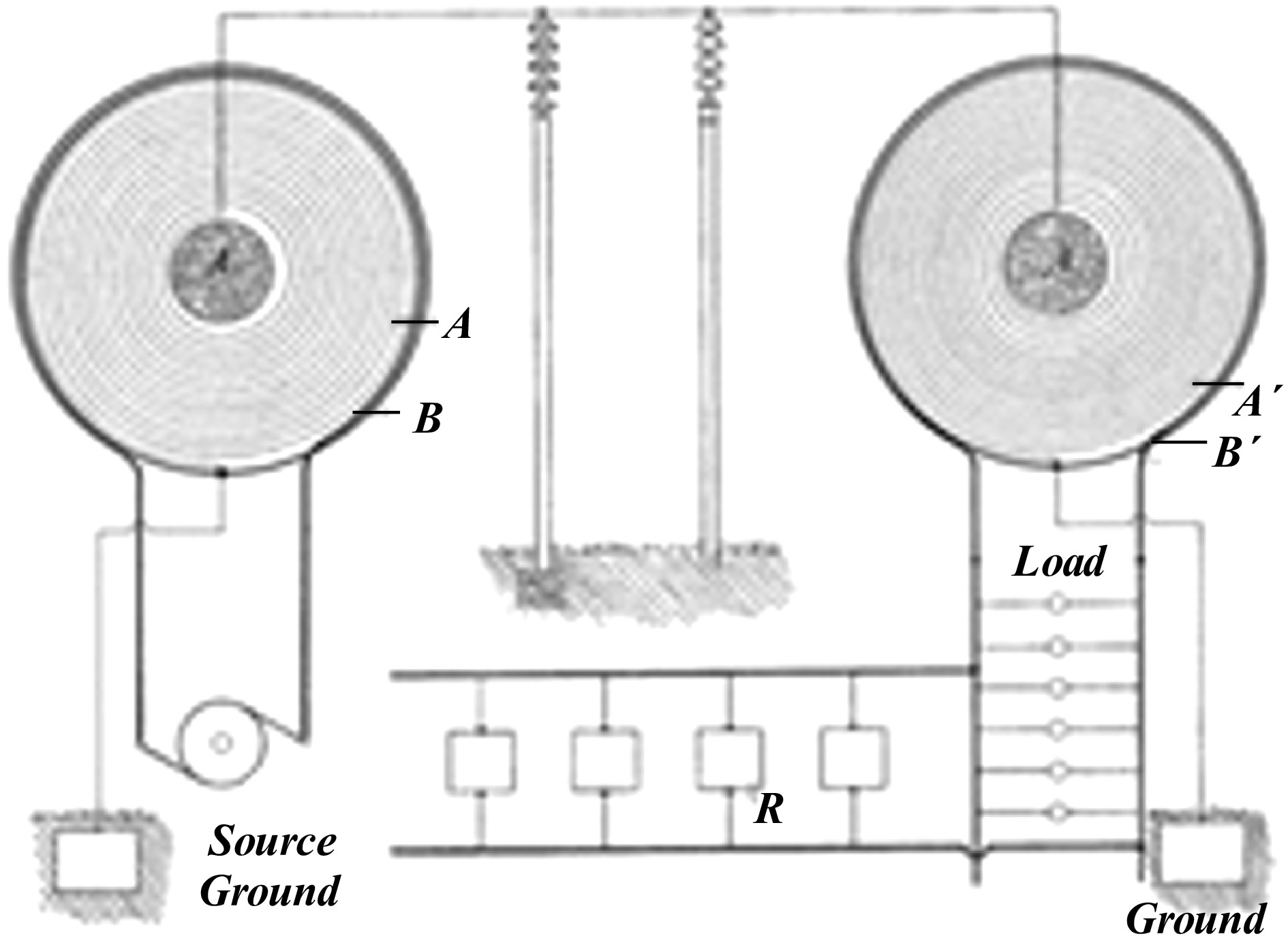
Figure 1.
Tesla's single-wire device.
Single-wire power transmission (SWPT) technology achieves power transmission through a single wire connection. The single "wire" can be a medium such as soil, seawater, or a metal plane. The unique characteristics of this technology make it a promising new research direction to break through the barriers of WPT technology, enabling efficient WPT.
To date, numerous studies on SWPT technology have been conducted, based on Tesla's concept, and attempts have been made to explain the principle of SWPT. One experimental study on SWPT[9] conducted an experiment on power transmission using a single wire. The single-line power transmission method and the related experimental study[10] simplified the device by connecting a coaxial cable to a single wire, proving that the coaxial cable, to a certain extent, works together with the single wire to constrain and guide the electric field. Research on high-frequency coupled resonant SWPT technology[11] used electromagnetic surface waves to explain the energy distribution and basic principles of the single wire, and built a SWPT device using a step-up coil. Another study on single-wire power transmission based on spatial electric field coupling[12] proposed an equivalent model for SWPT by using spatial capacitance to the equivalent air. The typical structure is shown in Fig. 2, where the red box indicates the large inductance used for boosting.
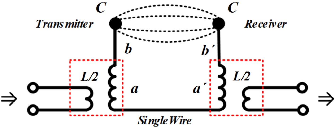
Figure 2.
Typical single-wire device.
According to the abovementioned literature, most of the existing single-line power transmission devices refer to the Tesla coil and spherical capacitor devices as envisaged in Tesla's technical scheme, and use similar external conductors such as axes or extension lines to transmit energy after boosting. This will make the system's volume larger, which is not conducive to practical application in actual scenarios. Traditional single line electrical energy transmission devices use open resonant circuits formed by large inductors and metal spheres or capacitor plates as coupling devices for energy transmission. There are problems, such asthe risks of high resonant voltage and significant environmental impact. When the resonant voltage exceeds the breakdown field strength of air, an arc discharge will form between the metal sphere or capacitor plate and the surrounding conductor or even the air, which not only causes additional energy loss and reduces the transmission efficiency, but also may burn the surrounding electronic components and insulation materials. In severe cases, it may even ignite nearby flammable media, causing fire or electrical hazards. Meanwhile, the open structure's electric and magnetic fields are directly exposed to the environment, and external factors such as humidity, dust, and foreign metal objects can significantly alter the resonance parameters. The topology proposed in this article adopts a resonant circuit composed of lumped inductors and capacitors, which concentrates the electric and magnetic fields generated during the resonance process mainly inside the circuit, greatly reducing the external electromagnetic radiation. The enclosed design restricts the resonance voltage inside the shell, avoiding the risk of air breakdown discharge and eliminating the potential impact of electromagnetic field exposure on the human body. When energy transmission is conducted through a single wire, the safety is greater. Enabling single-line energy transmission devices to adapt to more complex application scenarios enhances the flexibility and safety of practical applications.
In summary, this article proposes a new single-line transmission topology to address the potential safety issues associated with high-voltage transmission in SWPT systems. This article discusses the key factors that play a role in the SWPT system, simplifies the traditional structure, demonstrates the feasibility of removing the high-voltage link, and uses finite element software for simulation and verification by adopting a bilateral symmetric LCL topology to solve the problem of different load outputs under different single-wire connection modes after removing the high-voltage link. At the same time, an experimental setup was set up and experiments were conducted at different distances and with different connection methods. The load was still able to receive approximately 2 V of voltage energy even with an input of 12 V and 2 Mhz. After verification, the SWPT system could transmit energy without a pressurization device.
-
The system mainly studied in this paper is shown in Fig. 3. Unlike the LC resonance method used by Chen et al.[13], this system adopts the LCL resonance method. On the one hand, LCL resonance offers advantages over LC resonance in terms of harmonic suppression, impedance control, and load adaptability. On the other hand, the inductor L in the LCL can replace the Tesla coil used in the ordinary SWPT scheme to excite high-frequency electromagnetic waves in the transmission principle[13].
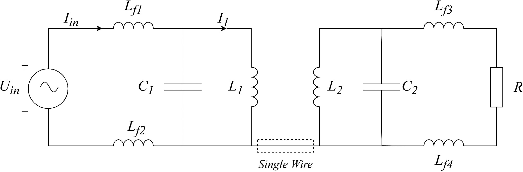
Figure 3.
Schematic diagram of the system.
To analyze the energy transmitted by the single wire, the transmitting end of the device with the LCL topology is extracted for separate analysis, as shown in Fig. 4. According to the basic principles of circuits, when the internal resistance of the wire is ignored, the total input impedance of the primary side is:
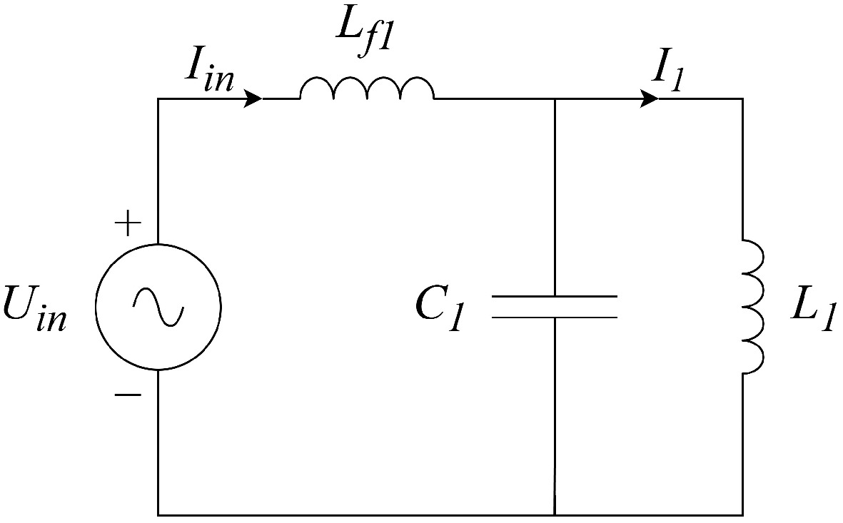
Figure 4.
Asymmetric LCL compensation topology.
$ {\dot{Z}}_{in}=j\omega {L}_{f1}+\dfrac{1}{j\omega {C}_{1}+\dfrac{1}{j\omega {L}_{1}}} $ (1) The input current
$ {\dot{I}}_{in} $ $ {\dot{I}}_{in}=\dfrac{{\dot{U}}_{in}}{{\dot{Z}}_{in}}=\dfrac{{\dot{U}}_{in}}{j\omega {L}_{f1}+\dfrac{j\omega {L}_{1}}{1-{\omega }^{2}{L}_{1}{C}_{1}}} $ (2) Therefore, the voltage across the primary compensation capacitor
$ {C}_{1} $ $ {L}_{1} $ $ {\dot{U}}_{{{C}_{1}}} $ $ {\dot{U}}_{{{L}_{1}}} $ $ {\dot{U}}_{{{C}_{1}}}={\dot{U}}_{{{L}_{1}}}=\dfrac{{L}_{1}{\dot{U}}_{in}}{{L}_{1}+{L}_{f1}-{\omega }^{2}{L}_{f1}{L}_{1}{C}_{1}} $ (3) The current
$ {\dot{I}}_{1} $ $ {L}_{1} $ $ {\dot{I}}_{1}=\dfrac{{\dot{U}}_{{{L}_{1}}}}{j\omega {L}_{1}}=\dfrac{{\dot{U}}_{in}}{({L}_{1}+{L}_{f1})j\omega -j{\omega }^{3}{L}_{f1}{L}_{1}{C}_{1}} $ (4) When the operating frequency of the system is
$\omega =1/\sqrt{{L}_{1}{C}_{1}}$ ${L}_{1}={L}_{f1} $ $ {\dot{I}}_{1}=\dfrac{{\dot{U}}_{in}}{j\omega {L}_{1}} $ (5) However, because of the asymmetry of the LCL topology, there are four connection methods for the single wire, as shown in Fig. 5.
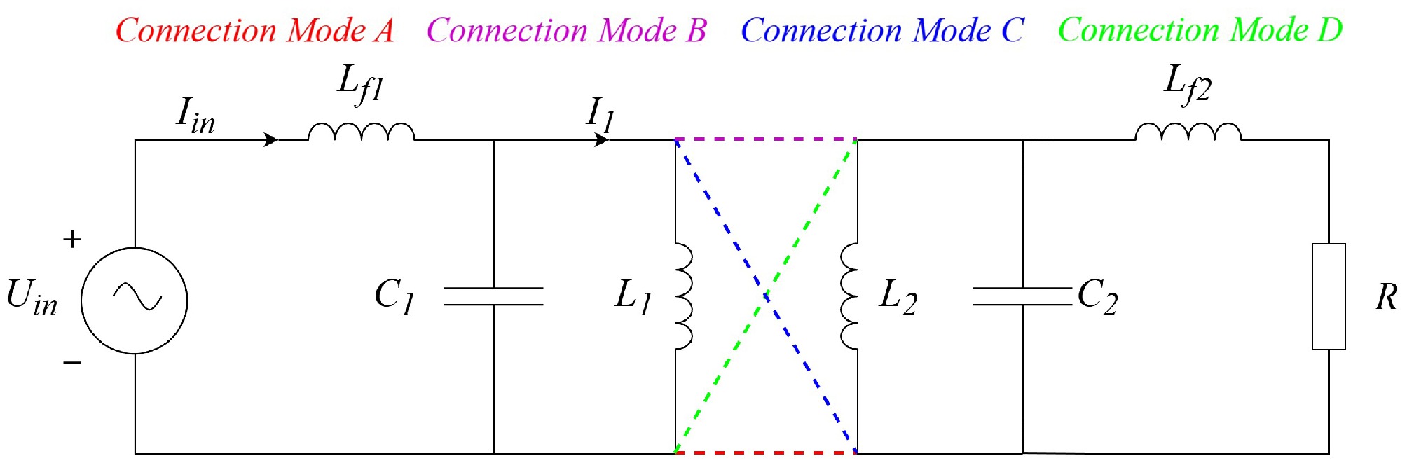
Figure 5.
Different connection positions of the single wire.
According to the analysis of the LCL topology in the previous text, the voltage across the inductor L1 is determined in a regular closed circuit. However, because of the special structure of a single wire, only one end of the single wire is connected to a certain endpoint in a closed circuit, which is fundamentally different from ordinary wires that transmit energy. The way a single wire is connected to only one endpoint means that it does not obtain voltage but constantly changing potential here.
Since one end of the single wire serves as the equivalent input source, the alternating current (AC) input obtained at different access points will vary, leading to differences in the transmitted energy. This also demonstrates that in an asymmetric LCL topology, the potentials at both ends of inductor L1 are not equal in absolute value at the same time. This introduces uncertainty into the system's analysis. To eliminate the impact caused by structural asymmetry, a comparison was made between the asymmetric LCL and the symmetric LCL systems, and their potential difference diagrams are shown in Fig. 6 According to circuit principles, in the asymmetric LCL topology,
$ {U}_{2}\neq {U}_{{{1}^{-}}} $ $ {U}_{2}={U}_{3} $ 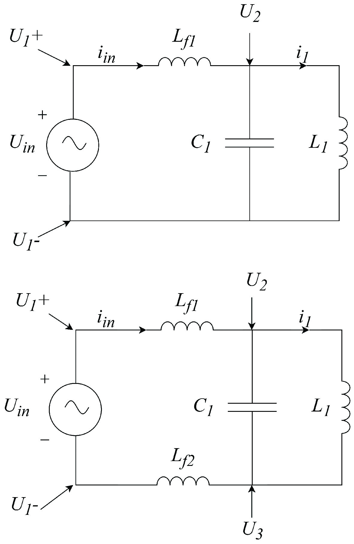
Figure 6.
Potential diagrams of different topologies.
For the symmetric LCL topology, the asymmetric LCL topology can be split
$ {L}_{f1} $ $ {L}_{1} $ Here, the inductor and the wire follow the basic laws of Maxwell's equations. When an alternating current is applied, an alternating magnetic field is excited in the surrounding space. According to Maxwell's extension of Faraday's law of electromagnetic induction, a changing magnetic field will excite an electric field in the surrounding space, thereby realizing the propagation of electromagnetic waves.
Guiding effect of the wire
-
Jin et al.[11] used electromagnetic surface waves to explain the energy distribution and basic principles of a single wire. By using Maxwell's equations, the boundary conditions
$ {k}_{\textit z}={k'_{\textit z}}={k''_{\textit z}} $ Here, eρ eφ ez are the basic unit vectors in the cylindrical coordinate system as the Fig. 7 showed;
$ \rho $ $ \phi $ $ {\textit z} $ 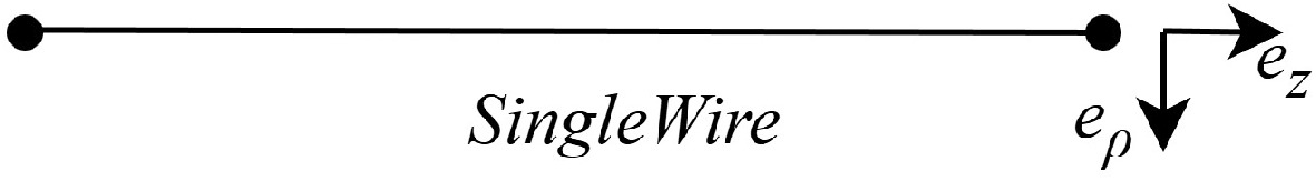
Figure 7.
The SWPT system in a cylindrical coordinate system.
$ \mathbf{S}=\dfrac{1}{2}{\overset{.}{\mathbf{E}}}_{s}\;\times\; \overset{.}{\mathbf{H}}_{s}^{*}=A{\mathbf{e}}_{\textit z}-B{\mathbf{e}}_{\rho } $ (6) $ \begin{split} & A=\dfrac{(\omega {\varepsilon }_{2}+\text{j}{\sigma }_{2}){\left| {\dot{H}}_{2}\right| }^{2}{k}_{1}\sin \theta }{2\sigma _{2}^{2}+2{\omega }^{2}\varepsilon _{2}^{2}}{\text{e}}^{-2\rho a}\\ & B=\dfrac{b\omega {\varepsilon }_{2}+g{\sigma }_{2}+\text{j}(b{\sigma }_{2}-g\omega {\varepsilon }_{2})}{2\sigma _{2}^{2}+2{\omega }^{2}\varepsilon _{2}^{2}}{\left| {\dot{H}}_{2}\right| }^{2}{\text{e}}^{-2\rho a}\\ & \left\{\begin{array}{l} b={\left[\left(m+\sqrt{{m}^{2}+{\omega }^{2}\mu _{2}^{2}\sigma _{2}^{2}}\right)/2\right]}^{\frac{1}{2}}\\ a={\left[{\omega }^{2}\mu _{2}^{2}\sigma _{2}^{2}/\left(2m+2\sqrt{{m}^{2}+{\omega }^{2}\mu _{2}^{2}\sigma _{2}^{2}}\right)\right]}^{\frac{1}{2}} \end{array}\right.\end{split} $ where,
$ \omega $ $ {\varepsilon }_{2} $ $ \nabla $ $ {\sigma }_{2} $ $ {\dot{H}}_{2} $ $ {k}_{1}\sin \theta $ $ {\mathbf{e}}_{\textit z} $ $ a $ $ {k}^{\prime\prime}=(b-ja){e}_{\rho }+{k}_{1}\mathrm{sin}\theta {e}_{\textit z} $ $ a $ $ b $ $ m={\omega }^{2}{\mu }_{2}{\varepsilon }_{2}-{k}_{1}{}^{2}{\sin }^{2}\theta $ $ g=a-1/\rho $ From the Poynting vector, it can be seen that the electromagnetic field transmits energy along the direction of the single wire ez. Because of the presence of the vector in the direction ep, a portion of the energy is also dissipated into the surrounding space. The exponential term in the formula
$ {\text{e}}^{-2\rho a} $ $ \rho $ In contrast to the traditional SWPT theory, we give our own understanding. From a macroscopic perspective, the principle by which a single wire constrains electric field lines is similar to electrostatic induction. A high-frequency alternating electric field will cause a similar charge induction phenomenon, which manifests as an induced current that changes with time, unlike the stable distribution of static charges in electrostatic induction. If a small segment of the single wire is taken as shown in Fig. 8, the charge distribution is analyzed at a specific moment, connecting one end to an AC power source will excite an alternating magnetic field inside the conductor. The green lines represent the induced current, the blue curves represent the electric field lines, and the red curves represent the magnetic field lines. The electric and magnetic fields excite each other, easily forming electromagnetic waves, which achieves the effect of energy transmission along the wire.
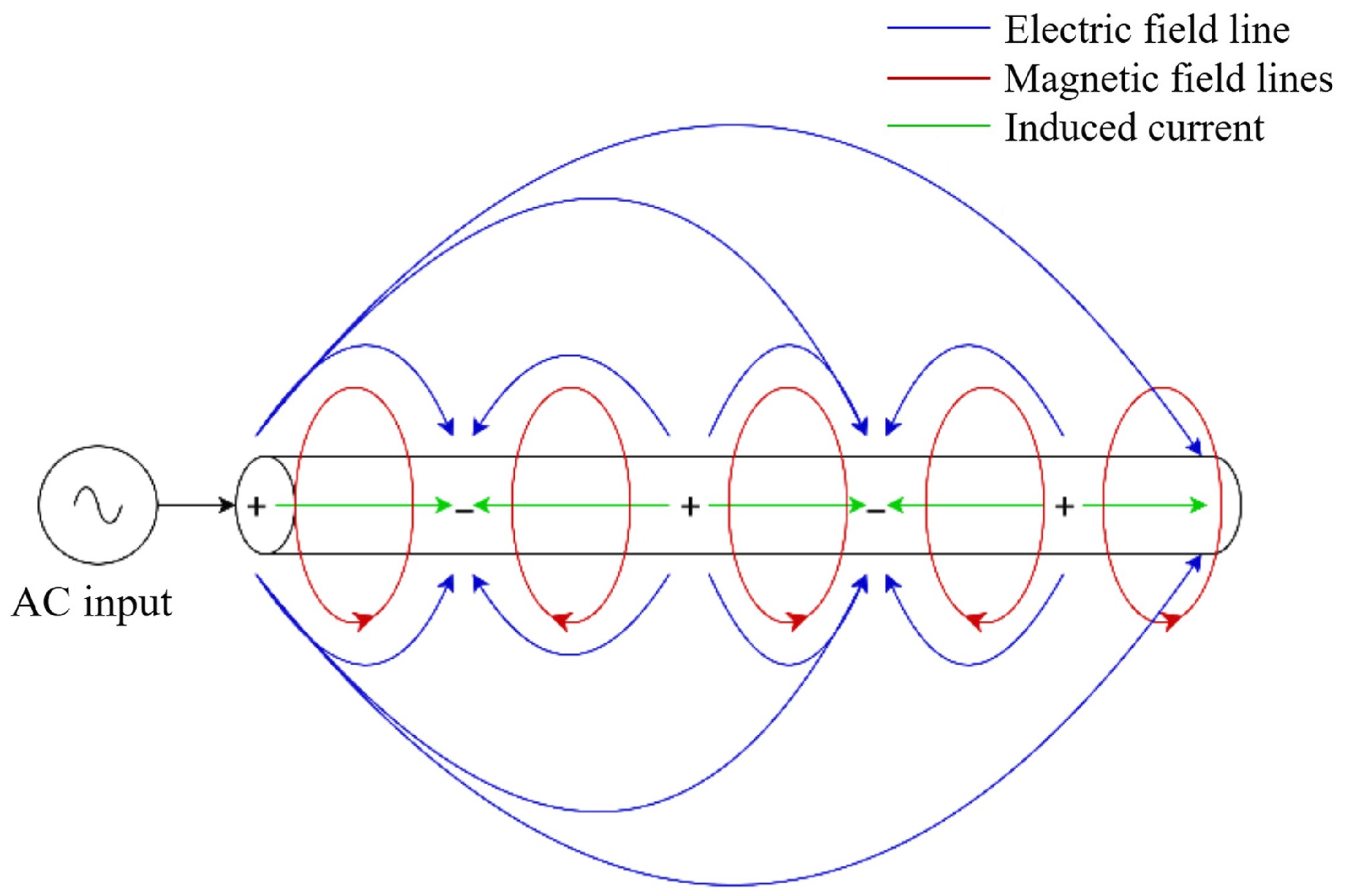
Figure 8.
Schematic diagram of electromagnetic induction in a single wire.
On the single line, the electromagnetic field is mainly concentrated in the area outside the single line. The variable electric field outside the single line will also generate current, mainly in the form of displacement current. The mathematical expression of the displacement current is:
$ {I}_{D}=\dfrac{d{\Phi }_{D}}{dt}=\dfrac{d}{dt}{\int}_{S}\mathbf{D}\cdot d\mathbf{S} $ (7) The direction of ID is related to the direction of the electric field. When it is greater than 0, they have the same direction; when it is less than 0, they have opposite directions.
According to the boundary conditions of the ideal conductor surface, the linear density K of the displacement current on the surface of a single conductor is related to the magnetic field's intensity, i.e.,
$ \mathbf{K}={\mathbf{e}}_{n}\times \mathbf{H} $ (8) where, en is the unit vector of the direction found on the outer surface of the single wire, and H is the intensity of the magnetic field on the surface of the single wire. At the same time, according to the classical Maxwell wave equation, when the system does not consider the influence of the source (that is, the system is in an electrostatic field or quasi-electrostatic field), the
$ \nabla \times \mathbf{E} $ $ {\nabla }^{2}u=\dfrac{1}{{c}^{2}}\dfrac{{\partial }^{2}u}{\partial {t}^{2}} $ (9) However,
$ {\nabla }^{2}=\dfrac{{\partial }^{2}}{\partial {x}^{2}}+\dfrac{{\partial }^{2}}{\partial {y}^{2}}+\dfrac{{\partial }^{2}}{\partial {z}^{2}} $ The general form of Maxwell wave equation can be obtained as follows:
$ {\nabla }^{2}\mathbf{E}(x,y,z,t)=\dfrac{1}{{c}^{2}}\dfrac{{\partial }^{2}\mathbf{E}(x,y,z,t)}{\partial {t}^{2}} $ (10) According to the formula above, when a high-frequency alternating potential is generated at a particular end of a closed circuit, electromagnetic waves will be transmitted according to Maxwell's equations, resulting in displacement currents along the single wire's direction to achieve energy flow.
-
According to the energy transmission principle explained above, the single wire is the key carrier for energy transmission. Therefore, in theory, energy transmission can still be achieved even after removing the external conductor parts such as the step-up coil and the spherical capacitor. In this section, finite element simulation software is used to verify the theory and propose a new SWPT system constructed using lumped-component LCL resonance. The parameters used in the simulation are shown in Table 1.
Table 1. Simulation parameters.
Parameter Value Length of the single wire 200 m Radius of the single wire 0.53 mm Input power supply 100 V Load 50 Ω In finite element simulation, the single wire, power supply, load, air domain, perfect matching layer, and so on are constructed as shown in Fig. 9. We can add the relevant physical field and select the 'electromagnetic wave, frequency domain' physical field in the RF module. In order to discuss the role of a single wire separately, copper is used as the material to construct a long wire in the model, the power supply and load use the lumped port, and the port's voltage is changed to form an excitation. The load has no excitation and the impedance is set to 50 Ω. Referring to Li et al.[10], a frequency of 2 MHz was selected for the simulation.
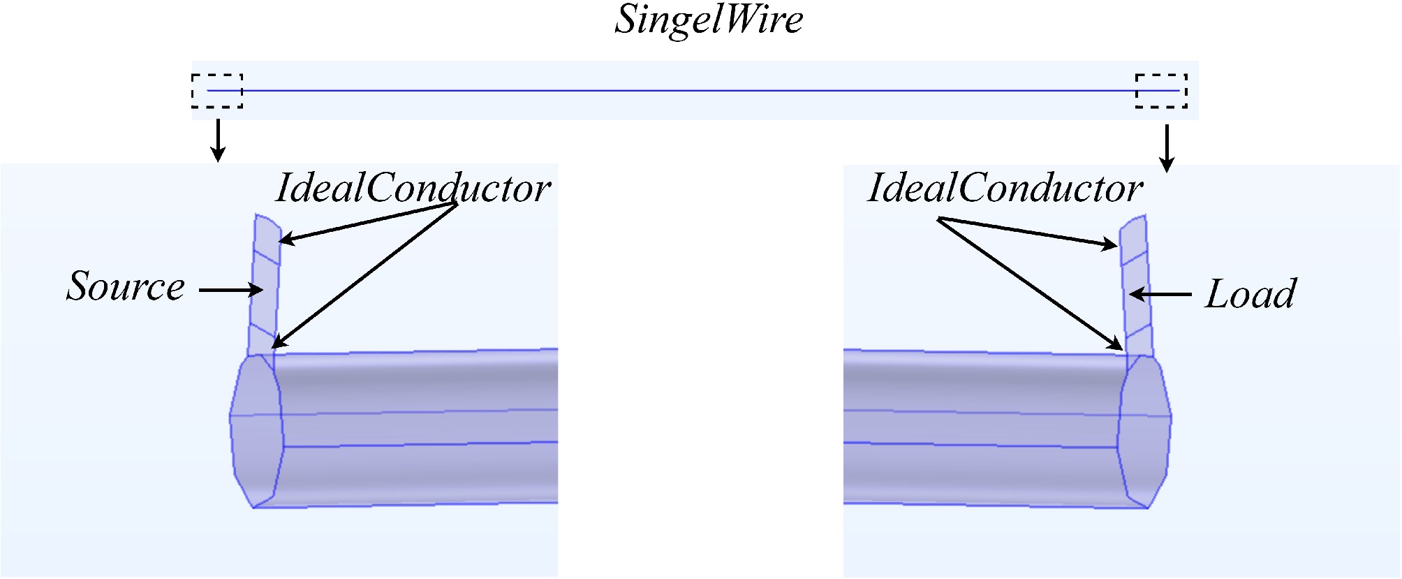
Figure 9.
Schematic diagram of the single-wire simulation.
A simulation experiment was conducted under the abovementioned conditions, and the results shown in Figs 10−12 were obtained.
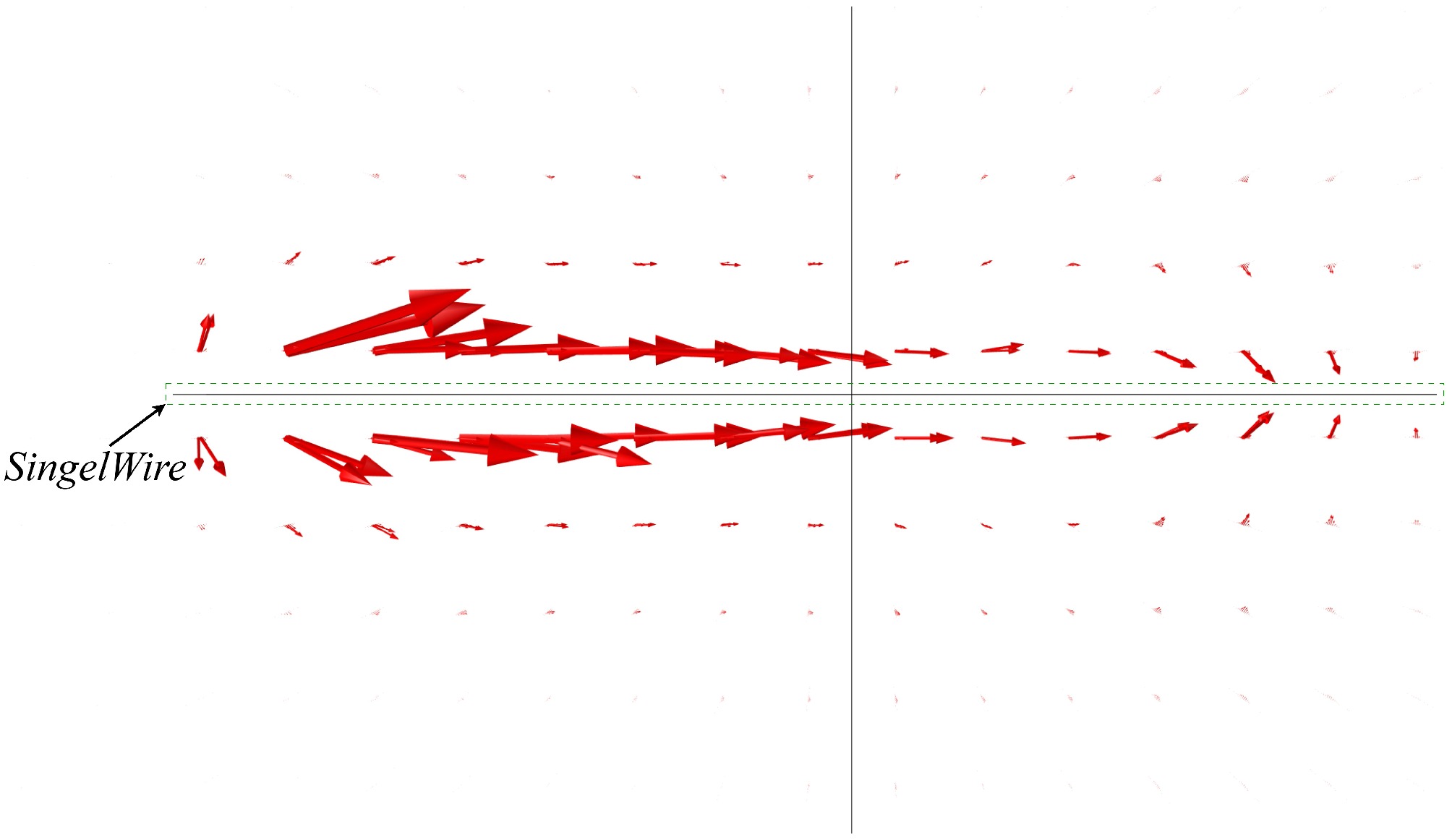
Figure 10.
Simulation result of the Poynting vector.
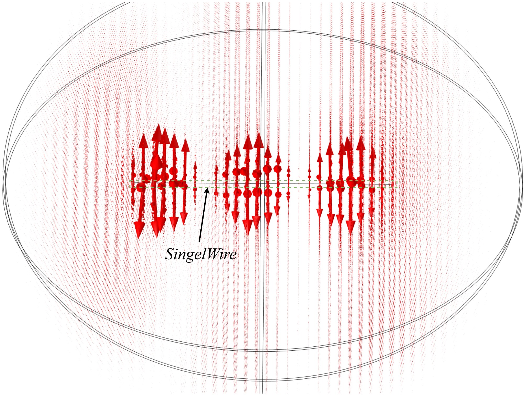
Figure 11.
Simulation result of the magnetic field.
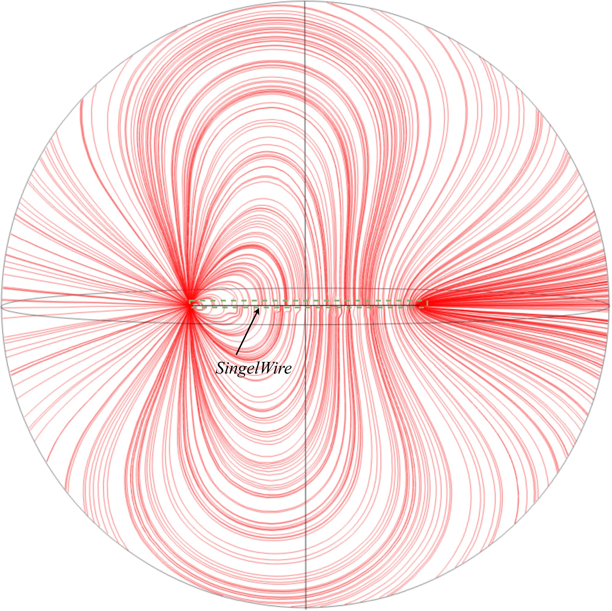
Figure 12.
Simulation result of electric field lines.
Analysis of the simulation results shows that even without coaxial cables or Tesla coils, the Poynting vector still moves along the direction of the wire, and the single wire can still conduct energy to the load end. Therefore, for short-distance SWPT applications, considering volume and safety issues and to eliminate the impact of redundant stray parameters on the system, Tesla coils or coaxial cables can be removed. This reduces the system's volume, improves safety, and facilitates the discussion of the role of different topologies on the single wire.
-
On the basis of the abovementioned theoretical analysis and simulation, we can confirm that the simulation's results conform to the distribution of electric and magnetic field lines in the theoretical analysis. Therefore, the energy flow in a single wire conforms to the theoretical analysis. In order to confirm whether the load energy under an asymmetric topology is affected by the connection method, we conduct comparative experiments with different connection methods one by one. The inverter plays the role of the AC source for the whole system and provides the basis for creating the electromagnetic environment of electrostatic induction. It does not play a unique and irreplaceable role in energy transmission.
Topology improvement verify
-
With a 15-V power supply connected to an inverter to obtain a 2-MHz AC input, experiments were conducted by adding aluminum plates to hinder magnetic coupling. The load voltage data were recorded in different connection states, and it was found that the load voltage would change differently when using different connection methods. The root mean square value showed two states: The load voltage was about 500 mV for connection methods B and D, and about 1.9 V for connection methods A and C.
It can be clearly seen that the connection methods B and D are affected by the asymmetric LCL topology, resulting in the load end not being able to effectively receive energy.
Therefore, according to the theoretical analysis, the topology is improved to a symmetrical form, as shown in Fig. 3. The use of a symmetric LCL ensures that, in theory, there is no significant difference in the energy received at the receiving end regardless of the connection method used for the single wire. We maintained the same experimental conditions, only changing the topology, and conducted experiments with different connection methods again. The experimental diagram of the different connection modes after using a symmetrical LCL coil is shown in Fig. 13 and Fig. 14 below.
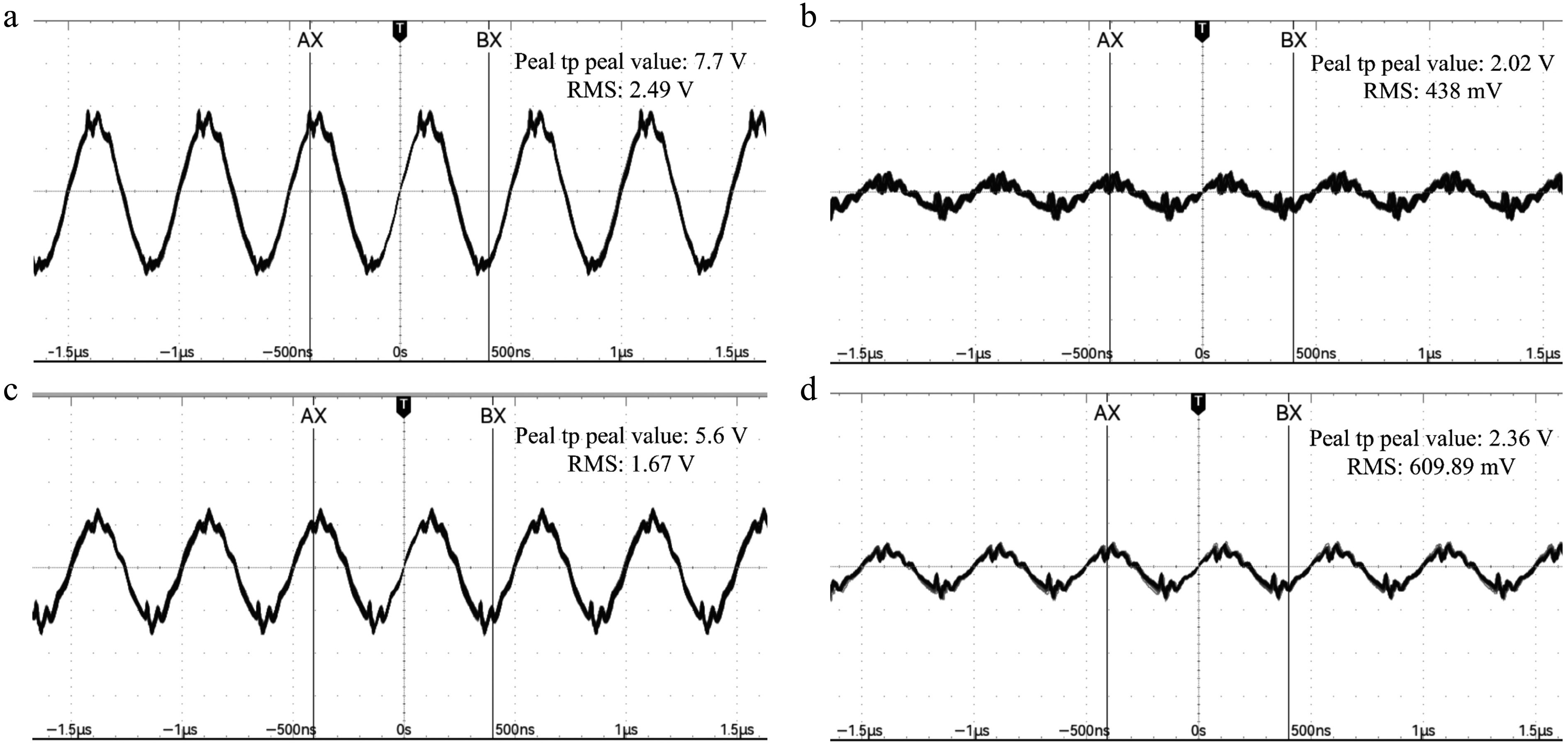
Figure 13.
Experimental schematic diagram of different connection methods for asymmetric LCL coils. (a) Connection mode A; (b) connection mode B; (c) connection mode C; (d) connection mode D.
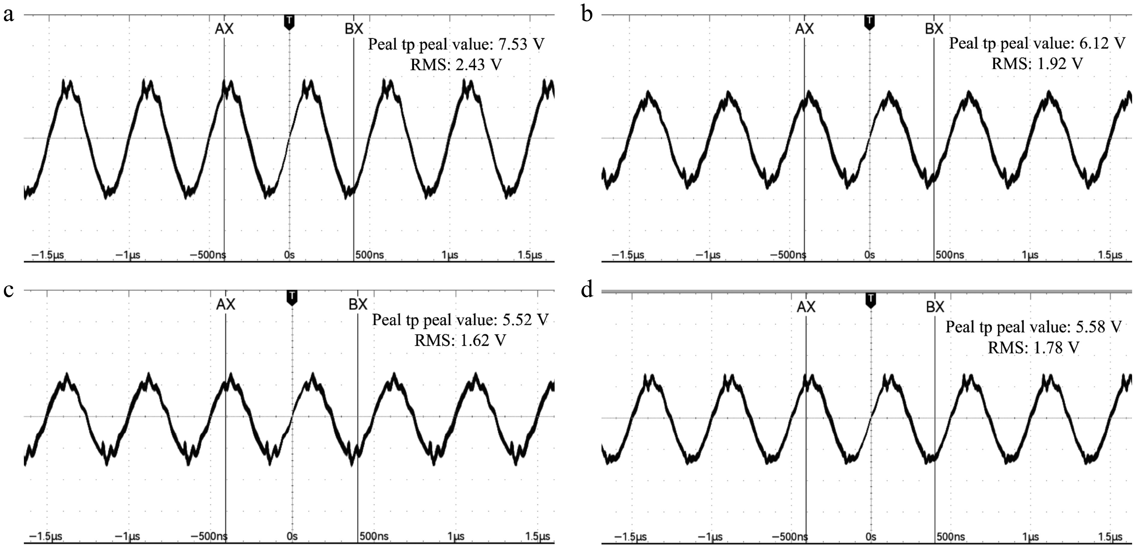
Figure 14.
Experimental diagram of different connection modes with a symmetrical LCL coil. (a) Connection mode A; (b) connection mode B; (c) connection mode C; (d) connection mode D.
Compared with the asymmetric LCL structure, it can be clearly observed that the load output in Modes B and D has improved, increasing from about 500 mV to around 1.9 V, reflecting the advantages of the symmetrical structure in a single line and solving the problem of different load outputs caused by the removal of high-voltage links as a result of different connection points.
Experimental equipment
-
According to the schematic diagram in Fig. 3, an experimental device was built as shown in Fig. 15 The input end used an inverter to obtain 12 V AC, with
$ {U}_{in} $ $ {U}_{R} $ $ {U}_{{{C}_{1}}} $ $ R $ 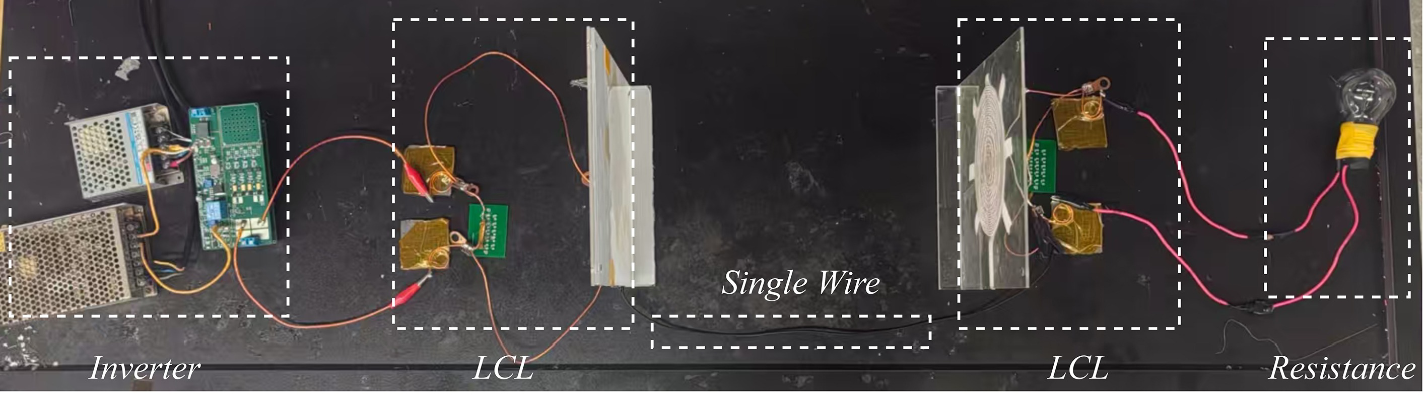
Figure 15.
Schematic diagram of the experimental device.
As shown in Fig. 16 is the voltage of the inverter. Fig. 17 illustrates the voltage across the primary capacitor, while Fig. 18 presents the voltage obtained at the load side, which is about 2V. The experiment proves that the relevant LCL topology can transmit energy on a single wire. However, because of the removal of the voltage boosting segment, the transmission efficiency is affected to a certain extent. In the future, the transmission efficiency can be improved by analyzing the operating frequency of the system and redetermining the topological tuning. LCL resonance can greatly improve the attenuation ability of higher harmonics through the cooperative filtering of two inductors. In LCL resonance, two inductors share the task of energy storage and filtering. Compared with LC resonance, a single inductor needs to store all the magnetic field energy, which can significantly reduce the rated current, volume, and loss of a single inductor. And the system's paramaeters are showed in Table 2.
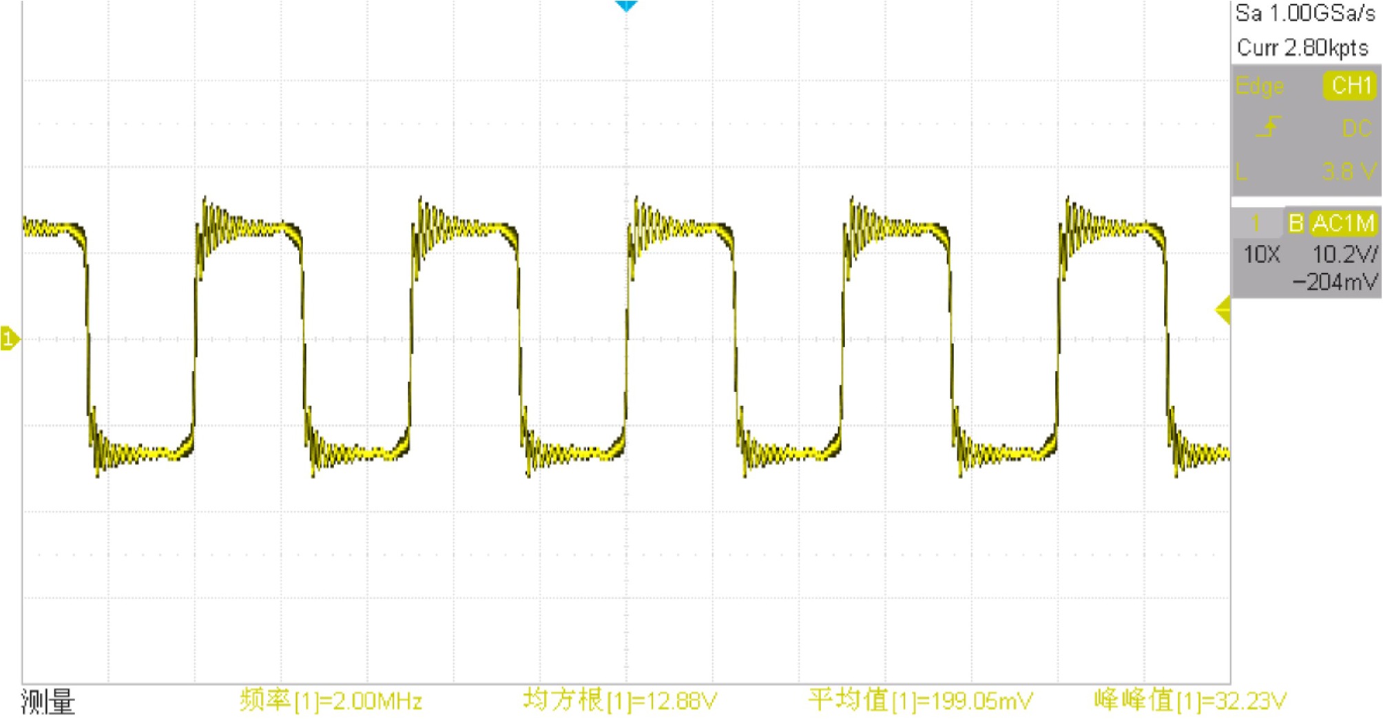
Figure 16.
Inverter voltage $ {U}_{in} $.
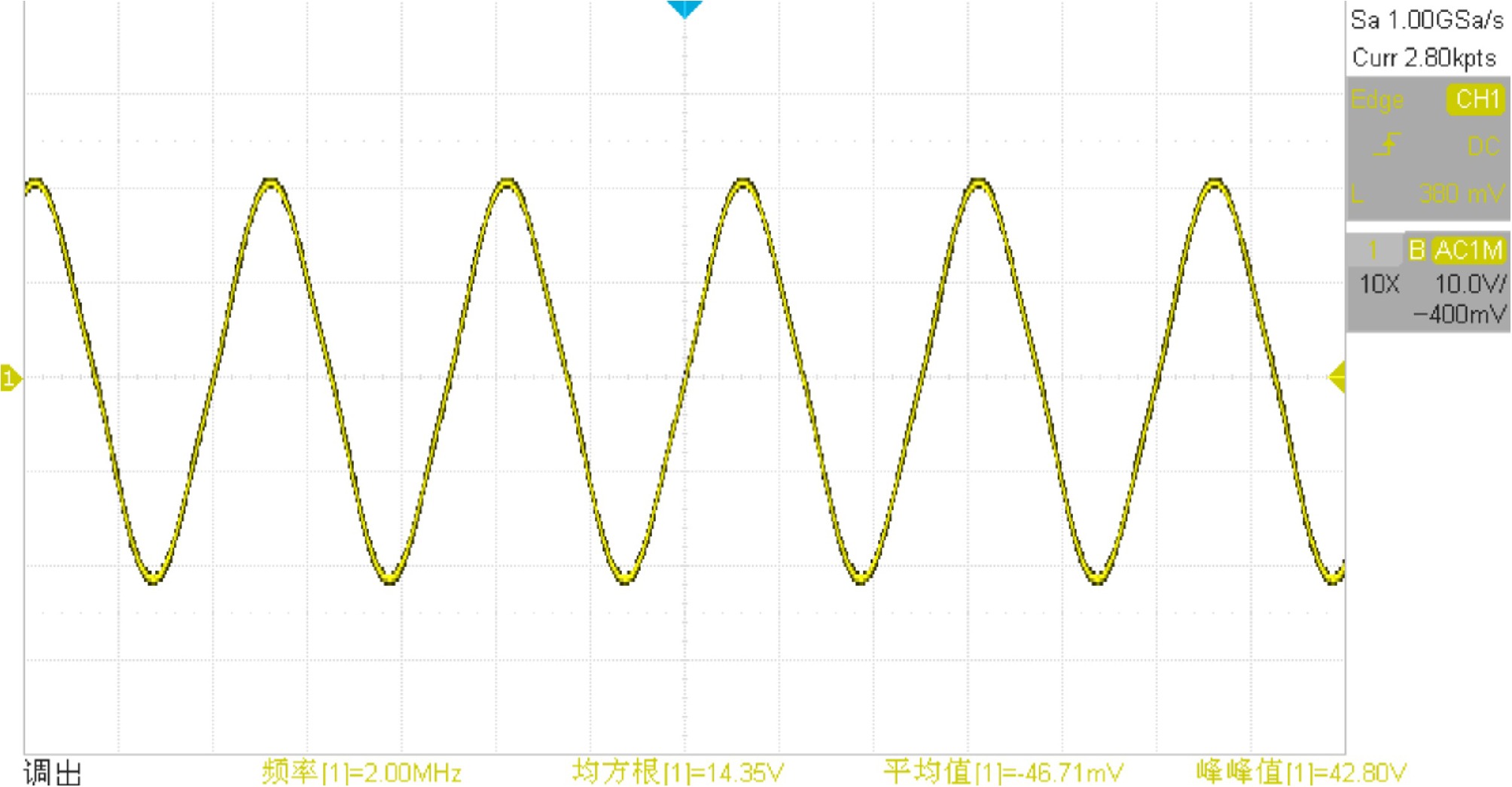
Figure 17.
Primary capacitor voltage $ {U}_{{{C}_{1}}} $.
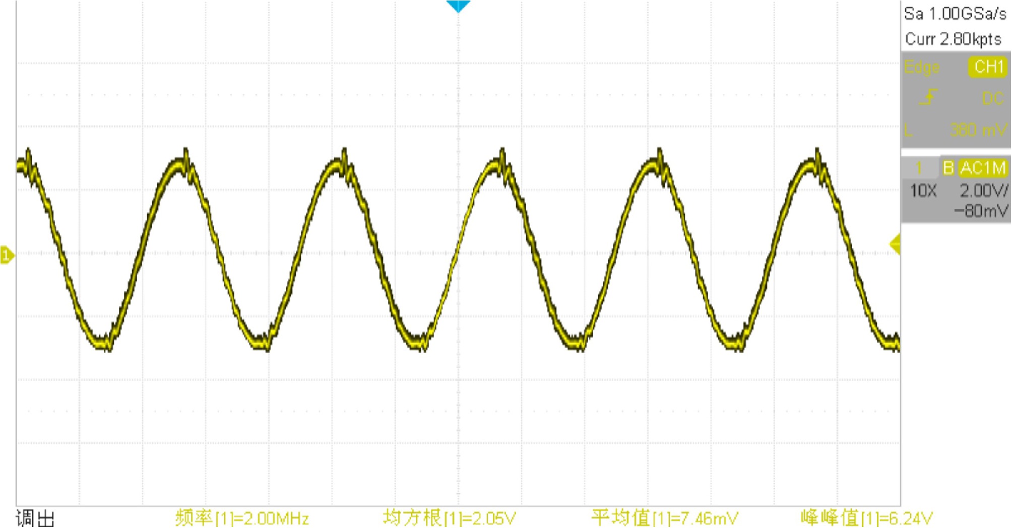
Figure 18.
Load voltage $ {U}_{R} $.
Table 2. The system's parameters.
Parameter Value LCL inductance 1.2 μH LCL capacitance 5.28 nF Diameter of the single line 2 mm Load resistance 50 Ω Effective value of the inverter's output voltage 12 V Working frequency 2 Mhz Effective value of load voltage 2 V Length of the single line 15 cm The core objective of this study is not to pursue high-power, high-efficiency energy transmission but to verify the guiding mechanism and feasibility of single-line energy. The use of 2 V of low-voltage AC output in the experiment is to eliminate the complexity of the circuit caused by high power and high voltage, such as increased difficulty in impedance matching and interference factors, in order to focus on verifying the core principle of single-line transmission and avoid the interference of noncore variables on the conclusions, providing new ideas for SWPT energy transmission. This principle can serve as the theoretical basis for engineering and power expansion of subsequent single-line energy transmission systems, rather than directly pursuing high-power output. The research focus is on the excitation and reception of single-line energy, and safety hazards such as unknown radiation can be controlled during the experiment. On this basis, the power can be gradually increased.
In the experimental verification phase of this study, we collected several groups of measured data under different experimental conditions. These data mainly cover the two core categories of single-wire energy transmission experimental data under different transmission distances and load terminal voltage data under different modes of connection. The datas are showed in Table 3.
Table 3. Experimental data chart.
Experimental scenario Peak to peak value Root mean square Load voltage under asymmetric connection method A 7.7 V 2.49 V Load voltage under asymmetric connection method B 2.02 V 438.05 mV Load voltage under asymmetric connection method C 5.6 V 1.67 V Load voltage under asymmetric connection method D 2.36 V 609.89 mV Load voltage under symmetrical connection method A 7.53 V 2.43 V Load voltage under symmetrical connection method B 6.128 V 1.92 V Load voltage under symmetrical connection method C 5.52 V 1.62 V Load voltage under symmetrical connection method D 5.58 V 1.78 V Single line length = 5 cm in Mode A 7.5 V 2.43 V Single line length = 10 cm in Mode A 7.7 V 2.42 V Single line length = 15 cm in Mode A 7.764 2.44 V Single line length = 20 cm in Mode A 7.88 V 2.49 V Single line length = 25 cm in Mode A 7.83 V 2.46 V Output under no load condition 9.6 V 3.32 V Discussion
-
In the analysis of the current in the experimental section, the energy in a single wire is not transmitted in the form of a traditional conduction current, but through electrostatic induction and a displacement current. This transmission mechanism has also been explained in other studies as magnetic surface waves, electric dipole coupling, and other forms. The measurement principle of traditional current probes is based on electromagnetic induction to detect changes in the magnetic field generated by the conducted current. However, in this system, there is no significant flow of conducted current within a single wire, and only the displacement current dominates the changes in the electric field. Therefore, when directly using a current probe to measure a single wire, effective readings cannot be detected. To ensure the authenticity and reliability of the experimental data, meaningless current data were not collected in the original experiment.
To address the issues of low power and efficiency in SPWT systems, a precise quantitative relationship between input and output has not yet been obtained in current research, making it difficult to directly determine the factors that affect efficiency. Therefore, we can improve transmission efficiency by readjusting or changing the topological structure. We can attempt to optimize the field distribution of electric field coupling by comparing and analyzing different topological characteristics and to explore the resonance frequency offset law of a single line transmission system on the basis of the change in the equivalent impedance of the system after removing the boosting link. Ultimately, an attempt can be made to obtain the optimal resonant frequency of the system.
Alternatively, we can explore the impact of various factors on transmission efficiency by changing the circuit's topology and using different wire materials. We can investigate the transmission efficiency of different wire materials under the same conditions, and combine the surface conductivity, dielectric constant, and other parameters of the related materials to analyze the correlation between material properties and related laws such as electrostatic induction and displacement current transmission[14,15].
Finally, we can refer to similar antenna methods to try to improve the efficiency and distance of electromagnetic wave transmission, drawing on the ideas of antenna impedance matching and radiation pattern optimization, and attempt to adjust the impedance to reduce energy loss[16].
According to the experiment described above, compared with other traditional single-line electric energy transmission devices, most of the devices mentioned in the introduction section use boosting devices or power amplifiers to amplify the energy at the transmitting end. In Li et al.[10], power amplifiers were used to enhance the energy intensity. In Jin et al.[11], the peak value of the voltage to ground on the single line reached 2.31 kV. In Chen et al.[13], Tesla boost coils were used. These other authors also believe that high voltage is a necessary condition for single-line energy transmission. This paper explains its non-necessity from the perspective of theoretical analysis, simulation, and an experiment.
-
In this paper, a single-wire energy transmission system with a symmetrical LCL topology based on lumped elements is proposed. The system uses a single wire to conduct electromagnetic waves to transmit energy, and realizes energy transmission via the single-wire energy transmission topology without Tesla coils. The simulation results are in good agreement with the theoretical results, which proves the guiding effect of a single line on electrical energy. The feasibility of energy transmission is verified by the actual device. Improving the LCL topology to a symmetrical form has improved the phenomenon of energy harvesting differences caused by different connection points in single lines.The disadvantage is that the transmission efficiency is not ideal.
The device has been improved again on the basis of Tesla's patents, which makes SWPT more compact and improves its feasibility in practical applications. In future research, the focus will be on how to obtain a specific quantitative relationship between the energy-conducting effect of wires. After clarifying the relevant theorems, we can improve transmission efficiency and power in a targeted manner while maintaining a small system volume and improve its applicability in practice.
-
The authors confirm their contribution to the paper as follows: study conception and design, draft manuscript preparation: Liu Q, Xiao J; data collection: Mo Yu, Wu X, Wu N; analysis and interpretation of the results: Liu Q, Xiao J; draft preparation: Mo Y, Wu X, Wu N. All authors reviewed the results and approved the final version of the manuscript.
-
The datasets generated during and/or analyzed in the current study are available from the corresponding author on reasonable request.
-
This project is supported by Guangxi Power Grid for its research GXKJXM20240162.
-
The authors declare that they have no conflict of interest.
- Copyright: © 2026 by the author(s). Published by Maximum Academic Press, Fayetteville, GA. This article is an open access article distributed under Creative Commons Attribution License (CC BY 4.0), visit https://creativecommons.org/licenses/by/4.0/.
-
About this article
Cite this article
Liu Q, Xiao J, Mo Y, Wu X, Wu N. 2026. A single-wire power transmission system based on LCL resonant circuits. Wireless Power Transfer 13: e013 doi: 10.48130/wpt-0026-0002 

A single-wire power transmission system based on LCL resonant circuits
- Received: 26 October 2025
- Revised: 14 December 2025
- Accepted: 19 December 2025
- Published online: 30 May 2026
Abstract: This paper presents a method to solve the problems of excessive system volume and security risks caused by the use of voltage-boosting devices in single-wire power transfer (SWPT) systems. The main contributions include putting forward the interpretation and understanding of the new SWPT principle, discussing the non-necessity of the boosting device as the theoretical basis, verifying the feasibility of non-high voltage energy transfer through finite element simulation, and optimizing the inductor-capacitor-inductor (LCL) topology to be symmetrical, which solves the problem of the different load output caused by different single-line connection modes while canceling the booster link. This method reduces the security risks and reduces the system's volume, which is more conducive to the application of engineering practice. Finally, a small-scale low-power SWPT experimental device was built to verify the feasibility of this method. The experiment shows that the load can receive about 2 V of voltage under the input condition of 12 V, which verifies the feasibility of this method.
-
Key words:
- Single-wire power transfer /
- LCL topology