


-
As a revolutionary technology, wireless power transfer overcomes the physical connection limitations of wired charging through non-contact energy transmission[1,2]. However, when applied to lightweight and thin scenes such as drones, traditional Litz wires based on magnetic structures face major challenges due to their volume and weight limitations[3]. Therefore, the key method of reconfiguring magnetic structures with PCB technology was born. However, replacing the Litz line with PCB winding still faces multiple bottlenecks: First, the encroachment of the insulating material on the window area reduces the cross-sectional area of the equivalent copper, increases the current density, and brings the risk of local overheating. Secondly, under high-frequency operation, the skin effect and proximity effect significantly aggravate the winding[4,5]. In view of these characteristics, PCB-based winding design requires systematic and collaborative research on core material selection, coil structure optimization, and thermal management strategies.
Aiming at the problem of high frequency eddy current loss in PCB windings, the concept of PCB Litzization in magnetic structure is innovatively proposed[6], and the performance of PCB Litz wire, multi-strand and solid PCB configurations is compared. This solution effectively reduces the high-frequency eddy current losses in PCB windings, although the complex layout increases the design difficulty. Professor Fred C. Lee improved the PCB-Litz winding layout and introduced a PCB-Litz structure with balanced magnetic field and current distribution for solid-state transformers[5,7]. However, these studies mainly focus on planar transformers and inductors, and the targeted research on optimizing the high-frequency loss of planar spiral coils in wireless charging systems is limited.
In this paper, a design of low-loss PCB Litz wire with a planar spiral coil is proposed. This structure combines the current distribution advantage of Litz wire with PCB technology by using a three-dimensional magnetic field balance layout and multi-layer current interaction design. Firstly, the coupling characteristics, core loss, and current loss of the proposed structure are analyzed. Then the finite element software is used to improve the parameters such as the number of conductor strands and the parallel turns of the coil. Finally, compared with traditional PCB coils, it was found that the resistance and loss were significantly reduced.
-
In the wireless charging system of consumer electronics products, the transmitter and receiver coils usually adopt a planar spiral coil structure. In this structure, the performance of the magnetic structure can be comprehensively evaluated according to k × Q (where k is the coupling coefficient and Q is the quality factor). When k remains constant, the Q value directly determines the performance of the coil. The Q value of the commonly used series-series (S-S) resonant network is as follows[8]:
$ Q=\dfrac{\omega L}{R} $ (1) Among these parameters, ω denotes the operating angular frequency of the system; L represents the self-inductance of the coil; and R stands for the total loss resistance, which encompasses the DC resistance, AC resistance, and core loss.
At high frequencies, the eddy current effect within conductors leads to a significant increase in winding AC losses. To quantify this phenomenon, a one-dimensional current density model is hereby introduced. For a single-turn winding, assuming that the magnetic field strengths on its two sides are H1 and H2, the D is winding width, and its σ and μ represent conductivity and permeability respectively, the winding loss P at an angular frequency ω can be computed using the following equations:
$ \begin{cases} J(x)=\lambda \dfrac{{H}_{1}\cosh [\lambda (D-x)]-{H}_{2}\cosh (\lambda x)}{\sinh (\lambda D)}\\ \lambda =\sqrt{j\omega \sigma \mu } \end{cases} $ (2) $ P=\dfrac{1}{2\sigma }\int\nolimits_{0}^{D}\left| J\left(x\right)\right|^{2}\mathrm{d}x $ (3) Skin loss and proximity loss constitute the predominant components of high-frequency AC losses in windings. Skin loss is primarily governed by the operating frequency and conductor dimensions, whereas proximity loss is contingent upon the magnetic field intensity induced by adjacent windings. Proximity loss escalates with increasing magnetic field intensity and is further modulated by winding width and operating frequency.
For core losses, the ferrite loss per unit volume can be characterized by the Steinmetz formula:
$ {P}_{\mathrm{v}}={C}_{T}\eta {f}^{\alpha }{B}^{\beta } $ (4) where, Pv is the ferrite core loss per unit volume, η is the material coefficient, α = 1.2−1.7, β = 2.2−4, and CT is the temperature coefficient of the ferrite loss. In planar spiral coils, the distribution of core loss varies with magnetic flux density B, which is itself influenced by winding distribution. Therefore, optimizing the winding layout is essential for minimizing core loss.
Notably, the magnetic field within a planar spiral coil is predominantly confined to the core region and is contingent upon the winding layout. In turn, the resulting magnetic field exerts a direct impact on winding loss. This mutual coupling among core loss, winding loss, and magnetic flux density highlights the necessity of a systematic optimization strategy to maximize the quality factor (Q) of the planar spiral coil.
In the following design, a ferrite shielding layer made of TDG's TPW33 material was selected, with a size of 50 mm × 50 mm × 1 mm. Within the working range defined by the Qi wireless power transfer standard, the PCB uses 4 oz of copper foil[9]. In this paper, the working frequency is 150 kHz, and the current through the PCB is set to 5 A. According to the IPC-2221 specification, the line width is designed to be 2 mm, and the spacing between adjacent coil lines is set to 1 mm. Each side of the PCB can accommodate six turns; taking into account the two-way winding configuration, a total of 12 turns can be accommodated. The inner diameter of the coil is 7 mm, and the outer diameter is 24 mm. The coil loss is mainly divided into core loss and winding loss. Firstly, the core loss is analyzed, and the scheme of minimum core loss is selected by changing the gap between coils. According to this, the core loss is mainly affected by the distribution of magnetic flux density B. The B value itself is controlled by the current flowing through the coil and the configuration of the coil winding. Therefore, this paper first ignores the resistance loss of PCB coils to isolate and study how different coil arrangements affect the distribution of core loss. Specifically, according to the standard PCB design guidelines, the minimum spacing between adjacent coil turns is set to 0.2 mm.
$ \begin{cases} 0.2 \lt ({l}_{1},{l}_{2},{l}_{3},{l}_{4},{l}_{5}) \lt 1\\ {l}_{1}+{l}_{2}+{l}_{3}+{l}_{4}+{l}_{5}\leq 5 \end{cases} $ (5) The position of each spacing parameter relative to the coil layout is shown in Fig. 1a. Taking Eq. (5) as the constraint condition, the relationship between coil spacing and core loss is analyzed by finite element simulation software, as shown in Fig. 1b. According to the simulation results, when the core loss is the smallest, l1, l2, l3, l4, and l5 are 0.2, 0.2, 0.2, 4.2, and 0.2 mm, respectively.
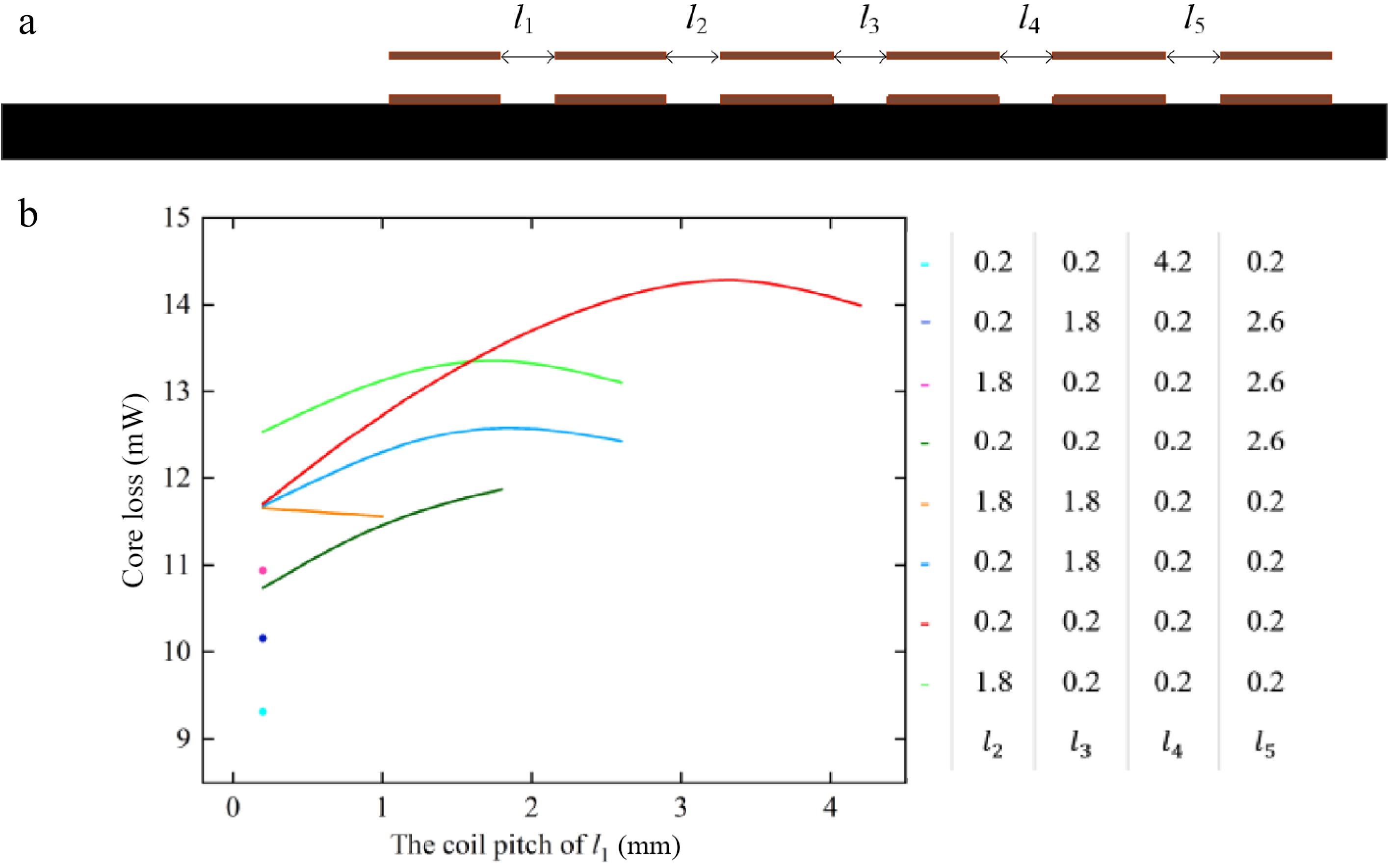
Figure 1.
Core loss optimization. (a) Coil spacing diagram. (b) Core loss and coil pitch characteristic curve.
From the above characteristics, it can be seen that when the coil distribution is shown in Fig. 2a, there is a small core loss. Therefore, the planar spiral coil based on PCB winding can be divided into two Litz regions. Given the typical circular arrangement of planar spiral coils, it is crucial to ensure equal length of each split copper strip to achieve balanced current distribution among post-photolithography conductors. This paper employs a grouped annular winding approach, leveraging the core design principles[3,5], to effectively balance core loss and achieve uniform current distribution throughout the coil. The proposed structure is shown in Fig. 2b, where the outer region denotes Region 1, and the inner region denotes Region 2. Within each group, a set of arc-shaped single-turn coils is constructed from the inner edge to the outer edge, with red lines representing top-layer conductors and blue lines representing bottom-layer conductors. For the setting of the Litz wire: let M denote the number of conductor strands, N the parallel turns, and P the winding turns. The rotation angle directly influences the spacing between coils and is constrained by PCB fabrication limitations. Specifically, each stranded wire is rotated by an angle θ1 to form a multi-stranded Litz coil with specific current-carrying capacity, followed by a unified rotation of θ2 to extend the structure from a single turn to a multi-turn configuration.
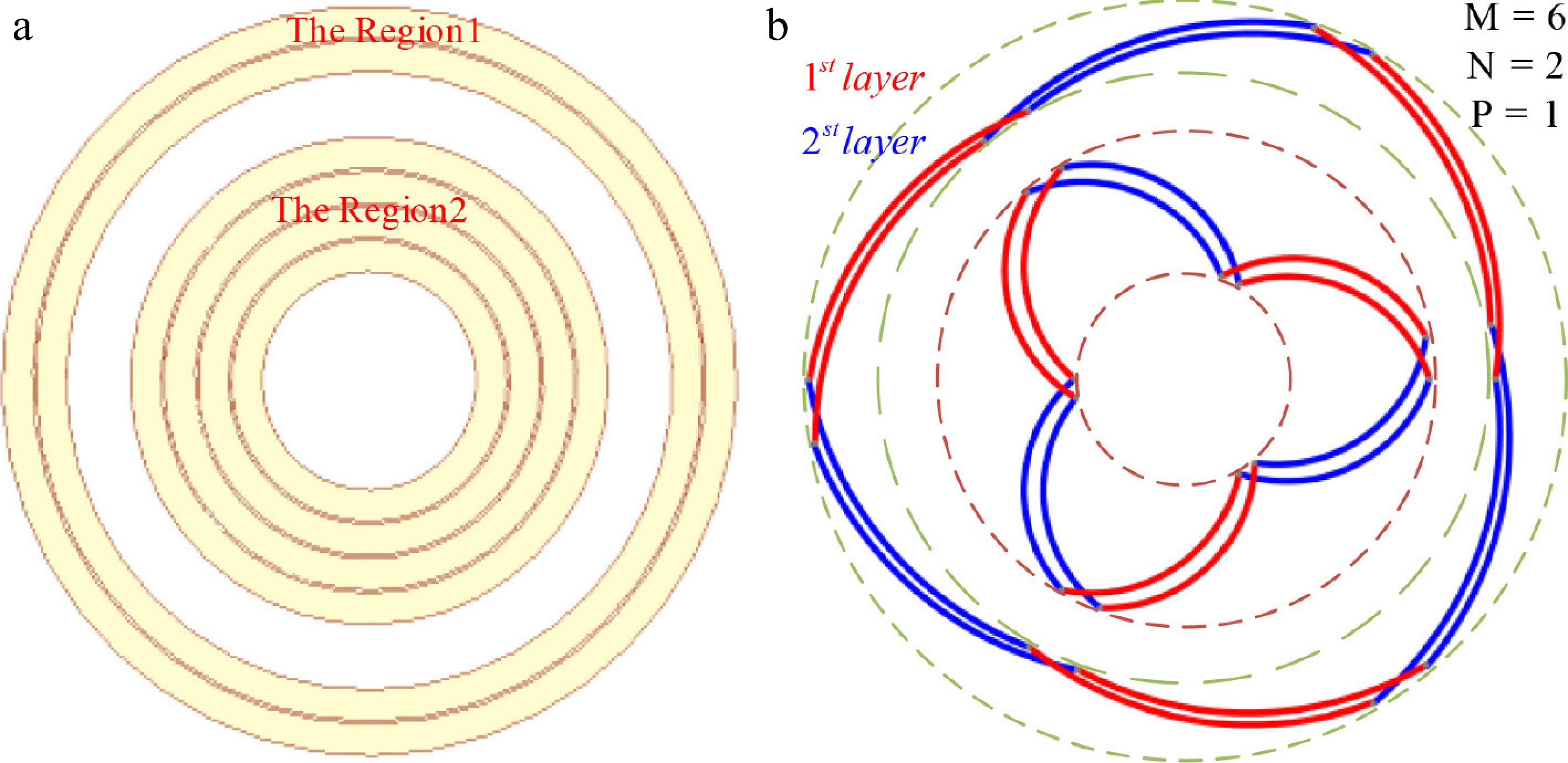
Figure 2.
The design Litz wire version of PCB for planar spiral coils. (a) The regions for PCB. (b) The grouped annular winding strategy for Litz wire version of planar spiral coils PCB.
$ {\theta }_{1}=\dfrac{{2}{\text{π}}}{M} $ (6) $ {\theta }_{{2}}=\dfrac{{2}{\text{π}} }{\dfrac{M}{{2}}\times N\times P} $ (7) Based on this design, a planar spiral coil based on PCB winding with Litz characteristics can be constructed, which can effectively reduce the loss of the coil and improve the efficiency of power transmission.
-
It can be seen from the previous section that the core content of the design scheme described in this paper is the Litz design of PCB. In addition, due to the limitation of the transmitting coil space in the wireless charging system, the width of the Litz configuration plane spiral coil must strictly conform to the size design specifications of Region 1 and Region 2. Specifically, under a fixed winding width, the maximum number of parallel strands in the wireless charging system is dictated by its spatial position. Concurrently, subject to the minimum line spacing requirements in PCB design, the variations in single-strand width and strand count exhibit an inverse relationship under the constraint of coil width.Under these characteristic influences, the DC resistance of the Litz-configured PCB winding increases with an increasing number of parallel strands (owing to reduced effective copper area), while the AC resistance decreases with an increasing number of parallel strands (attributable to high-frequency eddy current loss characteristics). To analyze the impact of strand count on coil impedance, finite spatial widths of Region 1 and Region 2 are utilized as illustrative examples. To control for a single variable and minimize errors, when Region 1 undergoes Litz wire segmentation, Region 2 remains unchanged; similarly, when Region 2 undergoes Litz wire segmentation, Region 1 remains unchanged.
Firstly, the number of conductor strands is optimized. It can be seen from Fig. 2 that Region 1 includes four rings, with an inner diameter/outer diameter of 19.8/24 mm, while Region 2 includes eight rings, with a diameter of 7/15.6 mm. The equivalent simulation of the Litz wire shown in Fig. 3a, b shows that with the increase of the parallel strands, the AC resistance decreases monotonously and the DC resistance increases monotonously. The total impedance shows a non-monotonic trend, reaching a minimum at three parallel chains in the two regions, as verified by the impedance optimization curve.
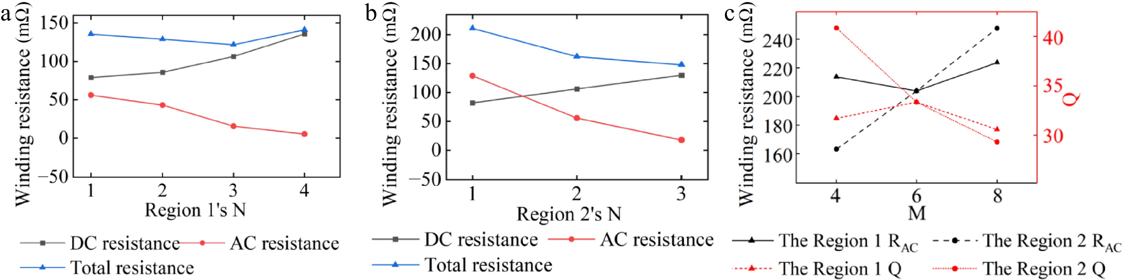
Figure 3.
Optimized winding resistance in both regions. (a) Region 1 resistance optimization. (b) Region 2 resistance optimization. (c) The influence of the number of conductor segments on resistance.
Further segmentation, analysis as shown in Fig. 3c, determines the best conductor segmentation: six segments for Region 1 and four segments for Region 2 at their respective minimum resistance conditions. This multi-parameter optimization demonstrates a systematic methodology for minimizing AC resistance in PCB-based inductive components while adhering to fabrication tolerances.
-
Based on the FEM analysis results, the final parameters of the adopted PCB Litz wire scheme in this paper are as follows: Region 1 features an outer diameter of 24 mm, an inner diameter of 19.8 mm, with three strands, each subdivided into four segments; Region 2 has an outer diameter of 15.6 mm, an inner diameter of 7 mm, with three strands, each subdivided into six segments. The thickness of the PCB is 0.6 mm.
Furthermore, FEM were conducted to evaluate the inductance and AC resistance of the conventional PCB layout, the structurally-optimized PCB design, and the proposed Litz-style PCB scheme across various frequencies. The corresponding quality factors were determined, as illustrated in Fig. 4.
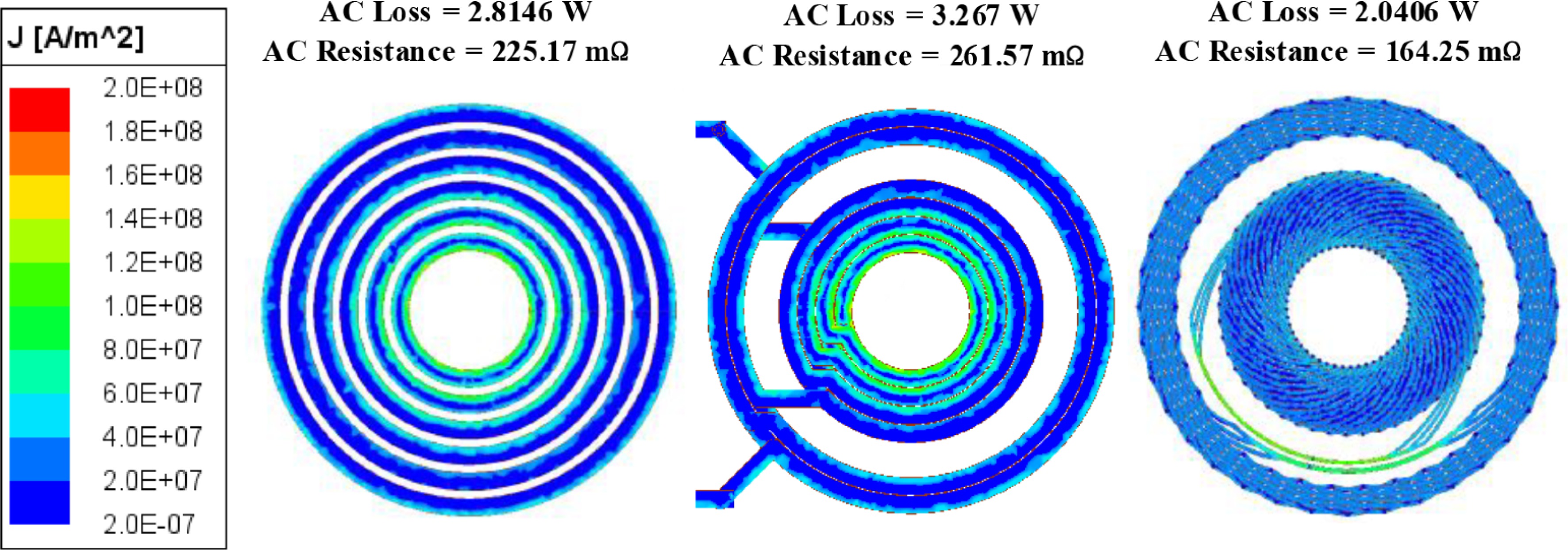
Figure 4.
Comparison of current density cloud diagram.
As observed from the illustrated current density contour, the Litz-style PCB exhibits a more uniform current density distribution, resulting in minimized AC losses and resistance at the operating frequency.
The inductance and AC resistance across various frequencies are subsequently simulated, and the Q is determined, as depicted in Fig. 5.
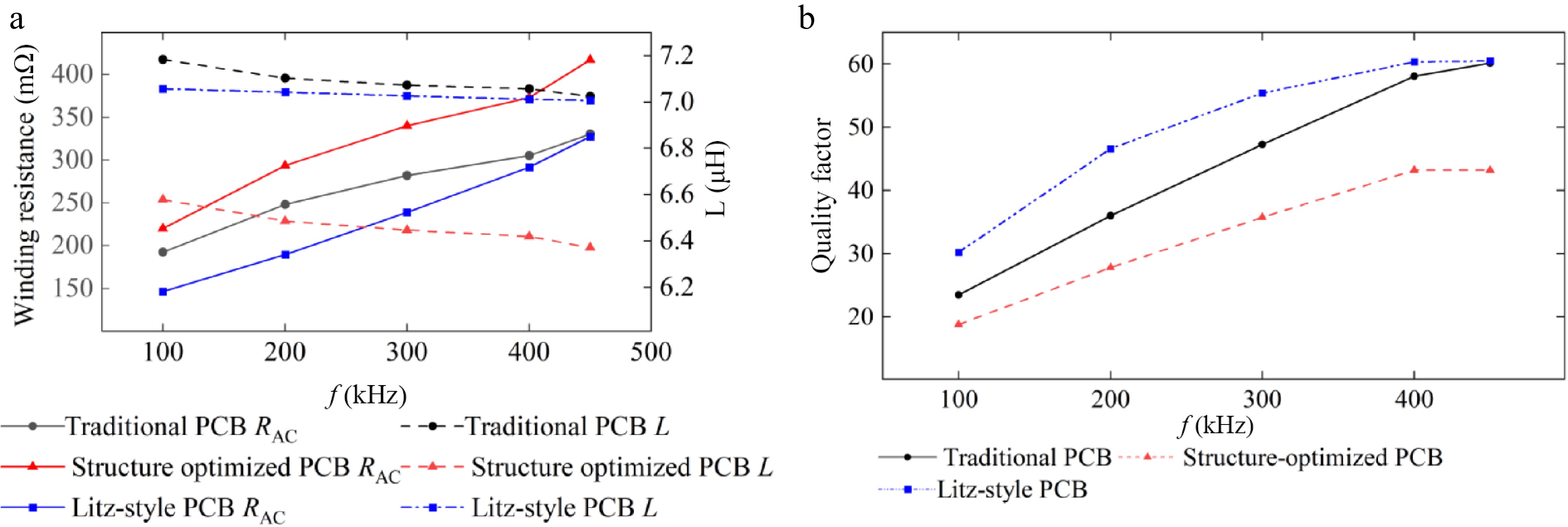
Figure 5.
FEM analysis inductance L, RAC, and quality factor data. (a) The inductance L and RAC. (b) Quality factor.
The results can be obtained from the FEM results described in Fig. 5. Under the constraint of an identical number of coil turns, the inductance of the proposed Litz-configured PCB coil falls in the medium range. Notably, with the smallest AC resistance among the three configurations, these results reveal that the coil’s AC resistance is not only dependent on winding width but also constrained by operating frequency and winding layout. Furthermore, the Litz-configured PCB coil achieves the optimal Q. Specifically, at the rated operating frequency of 150 kHz, its Q is 37% higher than that of the equal-width line spacing PCB scheme and 74% higher than that of the structurally optimized PCB scheme.
-
This paper addresses the issue of optimizing coil AC loss and quality factor by proposing a planar PCB coil design based on a Litz wire structure. Simulation results demonstrate that the proposed scheme effectively suppresses the skin effect and proximity effect in planar coils, significantly reducing the AC loss in wireless charging systems. Furthermore, the proposed circular coil design exhibits robust tolerance to rotational misalignment, thereby enhancing the energy transfer efficiency of the wireless charging system.
This work was supported by Basic Scientific Research Project of Liaoning Provincial Department of Education (Grant No. JYTMS20230799) and Major Research Projects of Ordos Institute of Liaoning Technical University (Grant No. YJY-ZD-2025-C-005).
-
The authors confirm contribution to the paper as follows: study conception and design: Huang W, Wang Q, Chen W; data collection: Wang Q, Guo R; analysis and interpretation of results: Huang W, Wang Q; draft manuscript preparation: Wang Q, Bai T, Zhang B. All authors reviewed the results and approved the final version of the manuscript.
-
The data that support the findings of this study are available from the corresponding author upon reasonable request.
-
The authors declare that they have no conflict of interest.
- Copyright: © 2026 by the author(s). Published by Maximum Academic Press, Fayetteville, GA. This article is an open access article distributed under Creative Commons Attribution License (CC BY 4.0), visit https://creativecommons.org/licenses/by/4.0/.
-
About this article
Cite this article
Huang W, Wang Q, Guo R, Chen W, Zhang B, et al. 2026. Design of low-loss PCB Litz wire with planar spiral coil for wireless power transfer. Wireless Power Transfer 13: e007 doi: 10.48130/wpt-0026-0004 

Design of low-loss PCB Litz wire with planar spiral coil for wireless power transfer
- Received: 10 October 2025
- Revised: 21 November 2025
- Accepted: 13 January 2026
- Published online: 09 March 2026
Abstract: Planar spiral coils in high-frequency wireless power transfer systems suffer from increased loss due to skin and proximity effects. The PCB Litz wire structure is proposed to suppress eddy current losses and improve the quality factor. Optimized design parameters are obtained through theoretical analysis and electromagnetic simulations. Simulation results confirm reduced AC resistance in the kilohertz range and a higher quality factor compared with conventional solid-wire coils. The proposed approach provides an effective solution for high-performance and compact WPT systems.