


-
Wireless power transfer (WPT) technology enables energy transmission from power sources to terminal devices without physical cable connections, offering significant advantages over traditional plug-in charging methods in terms of flexibility and safety[1,2]. With deepening research in academia and industry, WPT systems have been widely applied across various fields, including wireless charging for electric vehicles[3,4], smartphones[5], and drones[6,7]. However, WPT systems still face the critical challenge of insufficient output robustness, which limits further technological advancement. Specifically, variations in the relative position between transmitting and receiving coils cause significant fluctuations in output power and efficiency[8], posing risks to battery safety in terminal devices.
To address power stability issues in complex coupling environments[9], parity-time symmetric wireless power transfer (PT-WPT) systems have emerged as a research hotspot due to their ability to maintain constant power and efficiency despite changes in the coupling coefficient κ[10]. Originating from quantum physics, PT symmetry theory was initially applied to series/series (S/S) resonant WPT systems controlled by self-oscillating inverters[11]. Within the exact PT-symmetric region (κ ≥ κc), a balance between source gain and load loss is achieved. When κ exceeds the critical coupling coefficient κc, both output power and transmission efficiency theoretically remain invariant to κ variations—an ideal characteristic for WPT systems. In this region, the system's operating frequency automatically adjusts to maintain constant power output across varying transmission distances[12]. Additionally, PT-WPT systems offer practical advantages: detection and control circuits can be implemented solely on the primary side without wireless communication links, enhancing real-time responsiveness and stability while facilitating lightweight designs for charging devices. Despite achieving robust power output in the exact PT-symmetric region, conventional PT-WPT systems face limitations, including a narrow constant-power region[13,14] and inflexible power adjustment capabilities, restricting their widespread application. Specifically, in the PT-symmetry-broken region (κ < κc), output power varies significantly with κ. Therefore, expanding the constant-power region to accommodate diverse application scenarios remains a driving force for related research.
To extend the transmission distance of WPT systems, traditional approaches include parameter optimization[15]. Some studies have explored the use of magnetic materials[16] or relay coils to construct multi-coil PT-WPT systems. The three-coil PT-WPT system based on an S/S/PS compensation network[17] utilizes the PS compensation network to increase system order, achieving a smaller critical coupling coefficient and higher output power, thereby significantly enhancing performance in long-distance transmission scenarios.
However, the constant-power output of traditional PT-WPT systems is fixed and determined by their topological parameters[18], making it unable to meet power demands across diverse application scenarios. For example, in many wireless charging applications, such as smartphones and drones, adjustable output power is required to satisfy different power requirements. If traditional regulation methods such as altering loads or topological parameters are employed to change the output power, for example by adding DC-DC converters[19], additional losses will be incurred. This can easily disrupt the PT-symmetric state of the system, causing the constant-power characteristic to fail[20].
Meanwhile, in power regulation strategies for WPT systems, pulse density modulation (PDM), pulse frequency modulation (PFM), and phase shift modulation (PSM) are among the more common approaches. PFM adjusts power by changing operating frequency but risks deviating from resonance points, reducing efficiency[21]. PSM enables fixed-frequency power control but struggles with soft-switching in light-load conditions and generates high harmonic content[22]. In contrast, PDM modulates power by varying the density of energy transfer pulses within a fixed cycle. This approach maintains resonant operation, achieves soft-switching across wide load ranges, and improves system efficiency[23,24]. However, traditional PDM suffers from uneven pulse sequence distribution, resulting in large output current fluctuations and high harmonic content in high-frequency inverters. Under light-load or low-quality-factor conditions, it may even cause current interruption[25], which not only increases switching losses but also fails to meet the current stability and symmetry requirements of PT-WPT systems[26,27]. These limitations restrict the direct application of traditional PDM in PT-WPT systems.
To address the aforementioned limitations, this paper proposes an autonomous pulse density modulation (APDM) scheme for PT-WPT systems, targeting dynamic power demand scenarios such as in-flight drone charging. After applying this method to the PT-WPT system, it not only eliminates additional loads on the receiver side and simplifies control complexity, but also preserves the PT-symmetric state while enabling more flexible constant-power regulation, thereby expanding the application scope of PT-WPT systems.
In summary, the main contributions of the proposed scheme are as follows:
(1) A high-order topology with primary-series (S) and secondary-single-inductor-double-capacitor (SLDC) compensation is proposed, significantly expanding the constant-power region of the PT-WPT system.
(2) An APDM modulation strategy compatible with PT-WPT systems is introduced. By optimizing the pulse sequence to eliminate DC components and reduce current ripple, flexible regulation of constant-power output is achieved solely by adjusting the primary-side pulse density while maintaining system symmetry. This approach requires no additional topologies or hardware on the receiver side[28], and supports multi-mode power regulation, such as fast/slow charging for drones.
(3) The scheme integrates the zero-voltage switching capability of APDM with the autonomous frequency-tuning feature of PT-WPT. This enables soft-switching across the entire operating range, reduces switching losses, decreases the power consumption of in-flight drones, and extends their endurance, while enhancing system real-time performance and reliability.
-
The core advantage of PT-WPT systems lies in their ability to maintain constant output power within the strong coupling region. However, traditional S/S topologies exhibit a high critical coupling coefficient, resulting in a narrow constant-power region that struggles to meet long-distance transmission requirements. Thus, expanding the constant-power region is essential. This paper adopts the S/SLDC topology illustrated in Fig. 1a, which significantly expands the constant-power range. The system comprises a DC source with a GaN inverter, a primary S topology, a secondary SLDC topology, a load, and signal processing circuits. Here, Lp, Ls, and Lr denote the transmitting coil, receiving coil, and additional inductor, respectively; Cp, Cs1, and Cs2 represent compensation capacitors; while Rp, Rs, and RL correspond to the primary circuit internal resistance, secondary circuit internal resistance, and load resistance, respectively. The derivation of the output power formula for the PT-WPT system in the strong coupling region is presented as follows.
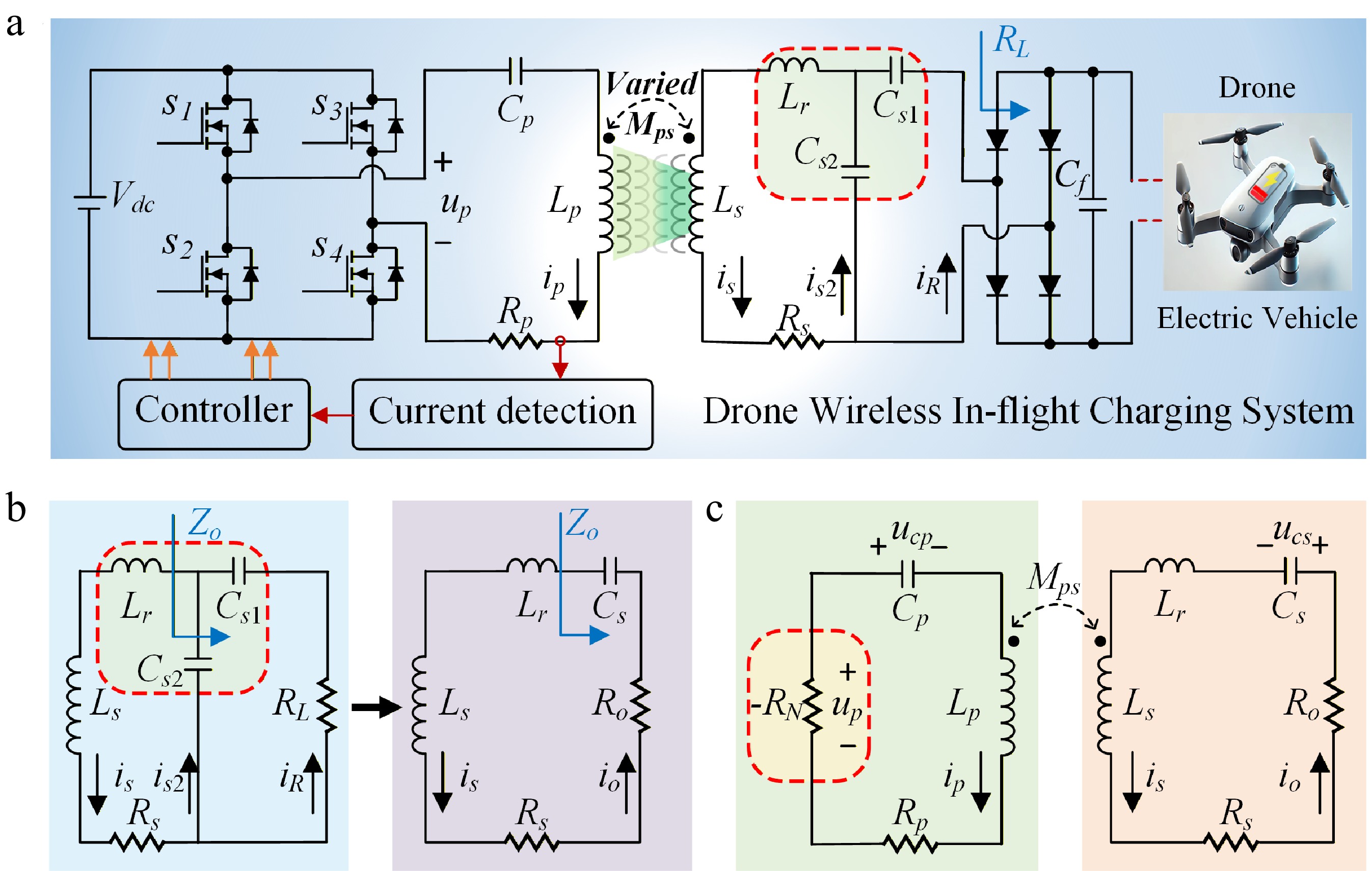
Figure 1.
Schematic of (a) the proposed drone wireless in-flight charging system. (b) Equivalent transformation of the SLDC topology. (c) Equivalent transformation of the system.
Figure 1b shows the equivalent circuit of the secondary side. The equivalent output impedance Zo can be expressed as:
$ \begin{split}{Z}_{o}=\;&\dfrac{1}{j\omega {C}_{s}}+{R}_{o}=\dfrac{1}{j\omega {C}_{s2}}//\left(\dfrac{1}{j\omega {C}_{s1}}+{R}_{L}\right)\\=\;&\dfrac{\left[{C}_{s1}+{C}_{s2}+{\omega }^{2}C_{s1}^{2}{C}_{s2}R_{L}^{2}\right]/(j\omega )+C_{s1}^{2}{R}_{L}}{{\left({C}_{s1}+{C}_{s2}\right)}^{2}+{\omega }^{2}C_{s1}^{2}C_{s2}^{2}R_{L}^{2}} \end{split}$ (1) Here, Cs and Ro represent the equivalent compensation capacitance and equivalent load resistance, respectively, which can be expressed as:
$ \begin{cases} {C}_{s}=\dfrac{{\left({C}_{s1}+{C}_{s2}\right)}^{2}+{\omega }^{2}{C}_{s1}{}^{2}{C}_{s2}{}^{2}R_{L}^{2}}{{C}_{s1}+{C}_{s2}+{\omega }^{2}{C}_{s1}{}^{2}{C}_{s2}R_{L}^{2}}\\ {R}_{o}=\dfrac{{C}_{s1}{}^{2}{R}_{L}}{{\left({C}_{s1}+{C}_{s2}\right)}^{2}+{\omega }^{2}{C}_{s1}{}^{2}{C}_{s2}{}^{2}R_{L}^{2}}\\ \end{cases} $ (2) This paper and the common PT-WPT system parameters satisfy ω2Cs12Cs22RL2 << (Cs1 + Cs2)2 and ω2Cs12Cs2RL2 << Cs1 + Cs2. Therefore, by defining the capacitance ratio λ, according to Eq. (2) we obtain:
$ \left\{ \begin{array}{l} C_{s}={C}_{s1}+{C}_{s2}\\ {R}_{o}=\dfrac{C_{s1}^{2}{R}_{L}}{{\left({C}_{s1}+{C}_{s2}\right)}^{2}}={\lambda }^{2}{R}_{L}\\ \lambda ={C}_{s1}/({C}_{s1}+{C}_{s2})\end{array}\right. $ (3) where, λ is the capacitance ratio with a value ranging from 0 to 1.
Therefore, based on the equivalent circuit method, the higher-order SLDC topology can be simplified to an LC topology. The equivalent circuit of the system is illustrated in Fig. 1c. Based on Fig. 1c, the circuit equations of the PT-WPT system can be expressed as:
$ \begin{cases} {L}_{p}\dfrac{d{i}_{p}}{dt}+{M}_{ps}\dfrac{d{i}_{s}}{dt}+{u}_{cp}+{i}_{p}{R}_{p}={u}_{p}\\ {M}_{ps}\dfrac{d{i}_{p}}{dt}+\left({L}_{s}+{L}_{r}\right)\dfrac{d{i}_{s}}{dt}+{u}_{cs}+{i}_{s}\left({R}_{s}+{R}_{o}\right)=0\\ {C}_{p}\dfrac{d{u}_{cp}}{dt}={i}_{p}\\ {C}_{s}\dfrac{d{u}_{cs}}{dt}={i}_{s}\\ \end{cases} $ (4) According to the coupled-mode theory, the energy modes ψp and ψs of the transmitting and receiving resonators can be described as:
$ \begin{cases} {\psi }_{p}={\Psi }_{p}{e}^{j\left(\omega t+{\theta }_{p}\right)}=\sqrt{\dfrac{{L}_{p}}{2}}{i}_{p}+j\sqrt{\dfrac{{C}_{p}}{2}}{u}_{cp}\\ {\psi }_{s}={\Psi }_{s}{e}^{j\left(\omega t+{\theta }_{s}\right)}=\sqrt{\dfrac{{L}_{s}+{L}_{r}}{2}}{i}_{s}+j\sqrt{\dfrac{{C}_{s}}{2}}{u}_{cs}\\ \end{cases} $ (5) where, ω represents the system operating angular frequency, Ψp and Ψs denote the amplitudes of the energy modes, and θp and θs are their corresponding phases.
The circuit state variables in the energy model can be expressed as:
$ \begin{cases} {i}_{p}={\Psi }_{p}\sqrt{\dfrac{2}{{L}_{p}}}\cos \left(\omega t+{\theta }_{p}\right)\\ {u}_{cp}={\Psi }_{p}\sqrt{\dfrac{2}{{C}_{p}}}\sin \left(\omega t+{\theta }_{p}\right)\\ {i}_{s}={\Psi }_{{s}}\sqrt{\dfrac{2}{{L}_{s}+{L}_{r}}}\cos \left(\omega t+{\theta }_{s}\right)\\ {u}_{cs}={\Psi }_{s}\sqrt{\dfrac{2}{{C}_{s}}}\sin \left(\omega t+{\theta }_{s}\right)\\ \end{cases} $ (6) Additionally, the resonant frequencies of the primary and secondary sides, along with the coupling coefficient, are given by the following expressions:
$ \begin{cases} {\omega }_{p}=1/\sqrt{{L}_{p}{C}_{p}}\\ {\omega }_{s}=1/\sqrt{\left({L}_{s}+{L}_{r}\right){C}_{s}}\\ {\kappa }^{\prime}={M}_{ps}/\sqrt{{L}_{p}\left({L}_{s}+{L}_{r}\right)} \end{cases} $ (7) Typically, the resonant frequencies of the primary and secondary sides are designed to be identical. After substituting Eqs. (5)–(7) into Eq. (4), ignoring high-frequency terms and applying the averaging method, we obtain:
$ \dfrac{d}{dt}\left[\begin{array}{c}\psi_p \\ \psi_s \\ \end{array}\right]=\left[\begin{array}{cc}j\omega_0+\dfrac{1}{\Psi_p}\dfrac{2V_{dc}}{\pi\sqrt{2L_p}}-\dfrac{R_p}{2L_p} & -j\kappa'^{\frac{\omega_0}{2}} \\ -j\kappa'^{\frac{\omega_0}{2}} & j\omega_0-\dfrac{R_s+R_o}{2\left(L_s+L_r\right)} \end{array}\right]\left[\begin{matrix}\psi_p \\ \psi_s \\ \end{matrix}\right] $ (8) Therefore, the frequency characteristic equation of the system is:
$ \left|\begin{array}{cc}j\left(\omega_0-\omega\right)+\dfrac{1}{{ }\Psi_p}\dfrac{2V_{\text{dc}}}{\pi\sqrt{2L_p}}-\dfrac{R_p}{2L_p} & -j\kappa'^{\frac{\omega_0}{2} }\\ -j\kappa'^{\frac{\omega_0}{2}} & j\left(\omega_0-\omega\right)-\dfrac{R_s+R_o}{2\left(L_s+L_r\right)} \end{array}\right|=0 $ (9) By separating the real and imaginary parts of the characteristic equation, Eq. (9) can be expressed as:
$ \begin{cases} \dfrac{{\kappa }^{'2}\omega _{0}^{2}}{4}-{\left(\omega -{\omega }_{0}\right)}^{2}+\left(\dfrac{{R}_{p}}{2{L}_{p}}-\dfrac{1}{{{\Psi }}_{p}}\dfrac{2{V}_{\text{dc}}}{\pi \sqrt{2{L}_{p}}}\right)\times \dfrac{{R}_{s}+{R}_{o}}{2\left({L}_{s}+{L}_{r}\right)}=0\\ \left(\omega -{\omega }_{0}\right)\left(\dfrac{1}{{{\Psi }}_{p}}\dfrac{2{V}_{\text{dc}}}{\pi \sqrt{2{L}_{p}}}-\dfrac{{R}_{p}}{2{L}_{p}}-\dfrac{{R}_{s}+{R}_{o}}{2\left({L}_{s}+{L}_{r}\right)}\right)=0\\ \end{cases} $ (10) Thus, the steady-state solution for the operating frequency ω can be expressed as Eq. (11), and the amplitudes of the energy modes in the proposed system can be expressed as Eq. (12).
$ \omega ={\omega }_{1,2}={\omega }_{0}\pm \sqrt{{\left(\dfrac{{\kappa }^{\prime}{\omega }_{0}}{2}\right)}^{2}-{\left[\dfrac{{R}_{s}+{R}_{o}}{2\left({L}_{s}+{L}_{r}\right)}\right]}^{2}} $ (11) $ \Psi_p=\Psi_s=\dfrac{2\sqrt{2L_p}\left(L_s+L_r\right)V_{dc}}{\pi\left[R_p\left(L_s+L_r\right)+\left(R_s+R_o\right)L_p\right]} $ (12) According to Eq. (11), when the operating frequency ω = ω0, the critical coupling coefficient κc of the proposed S/SLDC topology-based PT-WPT system is:
$ {\kappa }_{c}=\dfrac{{R}_{s}+{\lambda }^{2}{R}_{L}}{{\omega }_{0}\sqrt{{L}_{s}\left({L}_{s}+{L}_{r}\right)}} $ (13) In the PT-symmetric region, according to Eq. (11), the system's operating frequency can automatically stabilize at ω1 or ω2, rather than ω0. Meanwhile, the output power Pout and system efficiency η of the proposed system can be expressed as:
$ P_{out}=\dfrac{u_p^2R_oL_p\left(L_s+L_r\right)}{\left[R_p\left(L_s+L_r\right)+\left(R_s+R_o\right)L_p\right]^2} $ (14) $ \eta=\dfrac{R_o}{R_p\left(L_s+L_r\right)/L_p+R_s+R_o} $ (15) Figure 2 illustrates the relationship between the coupling coefficient κ and transmission distance for the proposed PT-WPT system based on the S/SLDC topology. Compared with the conventional S/S topology, the S/SLDC topology introduces an additional inductor and capacitance ratio, providing two extra degrees of freedom. This allows flexible design of system parameters to reduce the critical coupling coefficient κc, enabling APDM to maintain constant power regulation over a wider κ range and enhancing the flexibility and robustness of the in-flight charging system for drones. With the parameters selected in this scheme, the critical coupling coefficient is reduced from 0.2630 for the conventional S/S topology to 0.0715, and the constant-power region is extended from 0–60 to 0–140 mm.
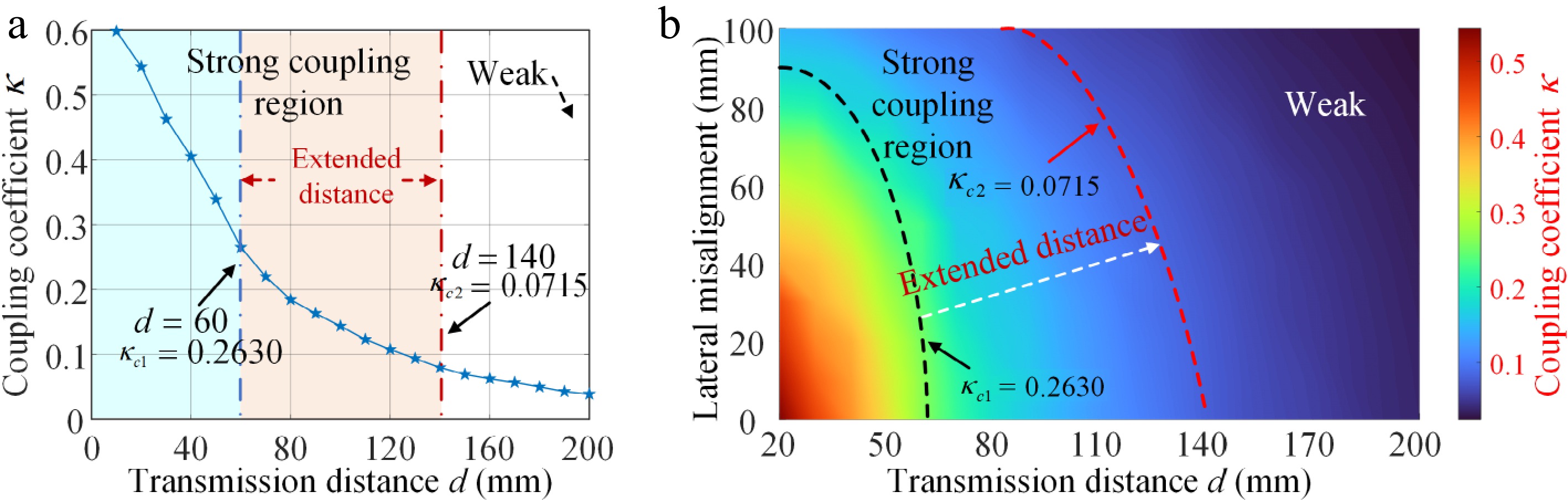
Figure 2.
(a) Effect of coupling coefficient κ on transmission distance. (b) Effect of κ on transmission distance and lateral misalignment.
Figure 3 shows the curves of output power and efficiency vs κ for the PT-WPT system. It can be observed that, compared with the common S/S topology, the proposed higher-order topology expands the constant-power region. In the exact PT-symmetric region, the power source gain and load loss reach a balance, and the output power is determined solely by the voltage and fixed topological parameters, independent of the coupling coefficient κ. When the coupling coefficient changes, the system maintains constant output power and efficiency.
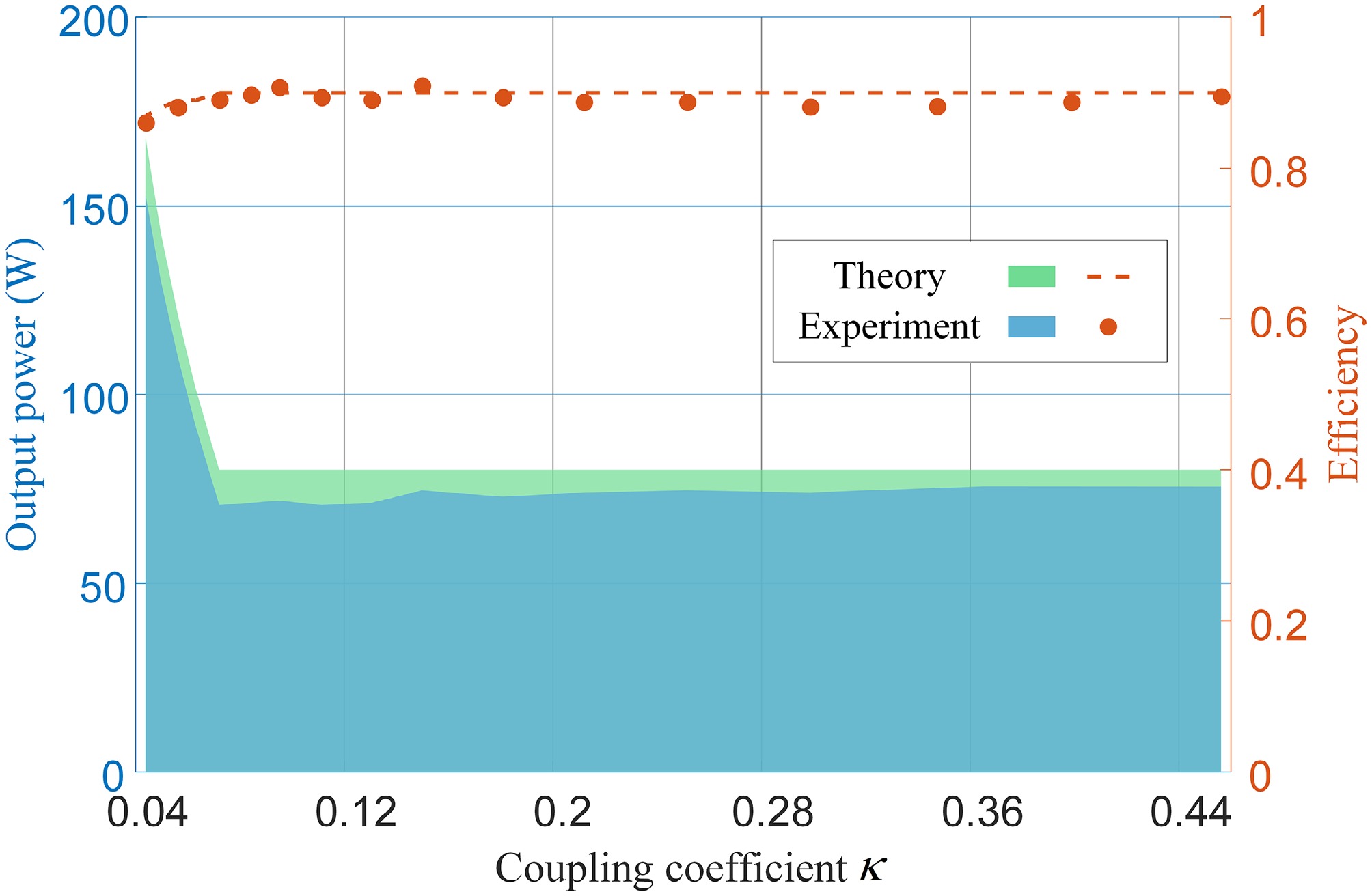
Figure 3.
Relationship between output power, transmission efficiency and coupling coefficient in the PT-WPT system.
PDM power regulation mechanism based on the PT-WPT system
-
Pulse density control is a modulation method where both the pulse frequency and duty cycle remain constant, while the output voltage RMS value is controlled by adjusting the pulse density (i.e., the number of pulses) within each modulation cycle (composed of multiple resonant cycles). The principle is illustrated in Fig. 4.
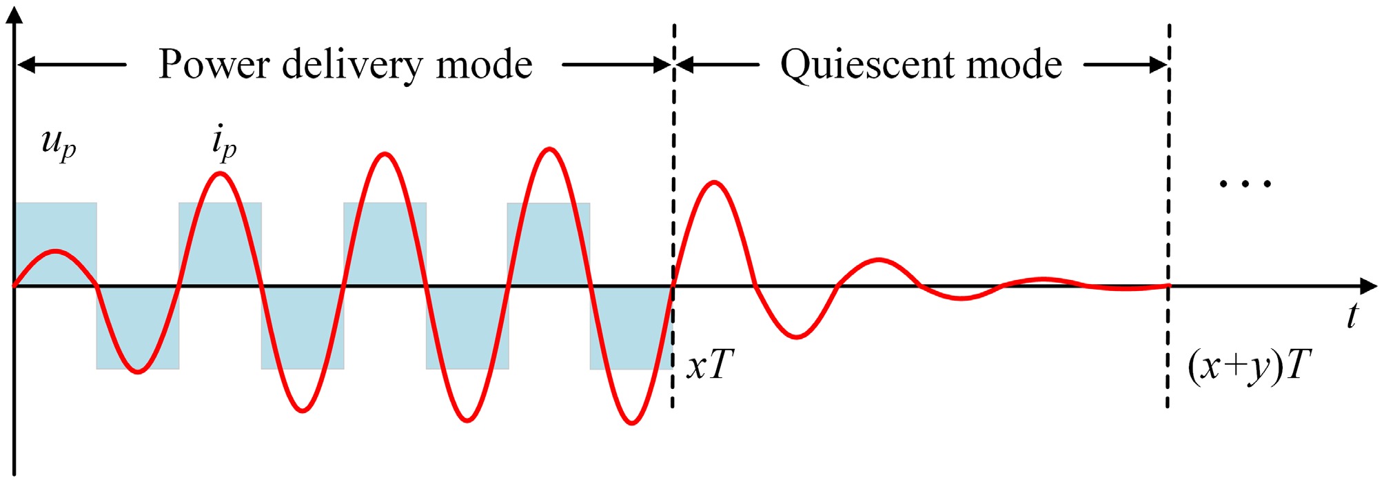
Figure 4.
Schematic diagram of PDM.
In the power delivery mode, the inverter triggers the switching devices at the resonant frequency f with a 100% duty cycle. The output voltage is a square-wave pulse with an amplitude of ± Udc, which injects energy into the WPT system, causing the output current to gradually increase. In the quiescent mode, the output voltage remains zero, and no energy is injected into the WPT system. The current within the resonant cavity oscillates freely, and due to continuous energy consumption on the output side, the current gradually decreases. By adjusting the proportion of these two modes within the modulation cycle—i.e., regulating the pulse density—the RMS value of the inverter output voltage can be precisely controlled.
As shown in Fig. 4 depicting the PDM output voltage waveform, let the modulation period consist of N = x + y resonant cycles, where x cycles correspond to the power delivery mode and y cycles to the quiescent mode. Defining the pulse density as m = x/(x + y), the fundamental RMS value of the inverter output voltage is given by:
$ {u}_{p}=m\dfrac{2\sqrt{2}}{\pi }{V}_{dc} $ (16) Therefore, the output power of the PT-WPT system under PDM modulation is expressed as:
$ P_{\text{PDM}}=\dfrac{8m^2V_{dc}^2R_oL_p\left(L_s+L_r\right)}{\pi^2\left[R_p\left(L_s+L_r\right)+\left(R_s+R_o\right)L_p\right]^2} $ (17) Equation (17) establishes the relationship between output power and pulse density. By adjusting the pulse density, power regulation is achieved. When the pulse density changes, only the constant-power value is altered while the critical coupling coefficient remains unaffected, realizing decoupled control between the modulation strategy and system output. That is, when the pulse density is fixed, the system maintains robustness against coupling coefficient variations (retaining the constant-power characteristic). This method breaks through the limitation of traditional PT-WPT systems where the constant-power value is 'fixed by topological parameters'. It enables flexible adjustment of the constant-power value without disrupting the PT-symmetric state, adapting to multi-scenario power demands such as drones and electric vehicles.
Compared to PFM and PSM, this approach reduces controller design complexity. Moreover, PDM modulation provides full-range linear adjustment of the fundamental RMS value of the inverter output, enhancing regulatory flexibility. Additionally, similar to PFM, PDM achieves soft switching for all four switching devices, significantly reducing switching losses in high-frequency applications like WPT. However, it is important to note that the pulse sequence design in PDM must satisfy the core conditions of PT symmetry: impedance symmetry and parameter stability. This is ensured through sequence optimization and soft-switching implementation.
-
To implement the proposed PT-WPT system, a phase synchronization method based on a Digital Signal Processor (DSP) controller is employed to realize negative resistance. The electronic controller of the system consists of a current detection circuit, compensation circuit, zero-crossing comparator, PDM generator, and gate drive circuit, collectively driving all power switches of the inverter. As shown in Fig. 5a, the detection circuit measures the phase and frequency of the primary current ip. Subsequently, the inverter generates a voltage that is in phase with the primary current.
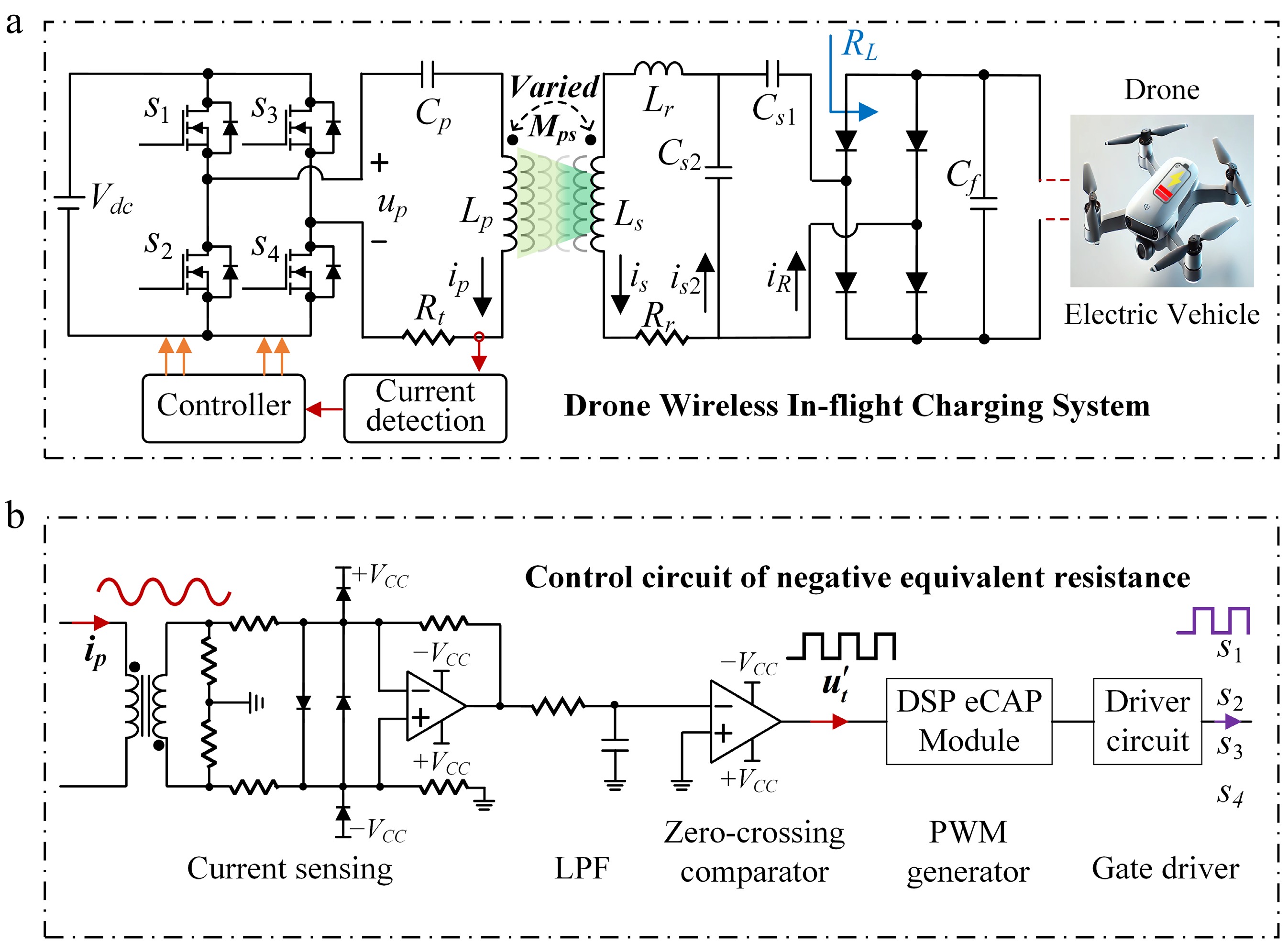
Figure 5.
Circuit design of the PT-WPT system employing APDM. (a) Power stage. (b) Block diagram of the controller.
The detailed controller scheme is illustrated in Fig. 5b. First, the current sensor detects ip, and a square wave up in phase with ip is obtained through a low-pass filter (LPF) and a zero-crossing comparator, respectively. The low-pass filter is used to mitigate disruptions caused by stray signal interference or ringing. The frequency and phase information are then identified via the eCAP module of the DSP. After receiving the preset value of m, the DSP calls the corresponding APDM sequence from Table 1 to generate a pulse-width modulation signal that is synchronized in both frequency and phase with the current. Finally, the gate drive circuit accurately drives the full-bridge inverter without requiring real-time feedback.
Autonomous pulse density modulation
-
During the PDM modulation process, the same modulation density yields identical fundamental RMS values. However, the more concentrated the energy injection method, the larger the peak response, due to the superposition effect. After the energy is completely depleted, the response decays to zero. In practical systems, this results in significant oscillations in the resonant cavity current, and may even cause current interruption at low modulation densities. In contrast, relatively uniform PDM sequences produce current responses with smaller oscillation amplitudes, as shown in Fig. 6a and b.
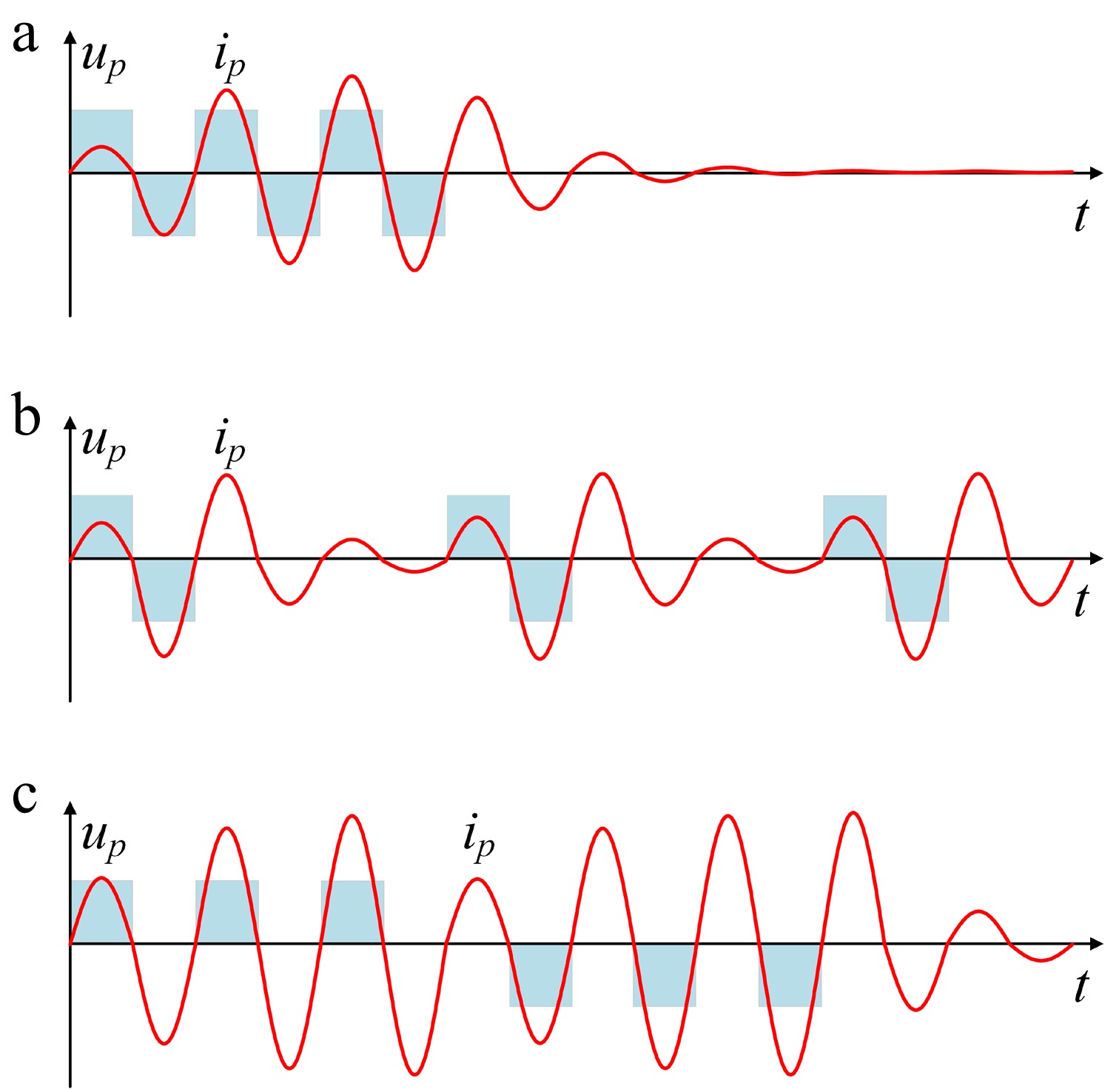
Figure 6.
Schematic diagrams of full-wave and half-wave PDM modulation. (a) Response under densely distributed full-wave PDM. (b) Response under uniformly distributed full-wave PDM. (c) Response under uniformly distributed half-wave PDM.
In traditional PDM modulation, the energy injection mode operates in a full-wave manner, meaning that energy injection within one modulation cycle occurs on a per-cycle basis. If a single-cycle pulse is decomposed into two independent positive and negative half-wave pulses, the number of energy injections becomes twice the original value, while the amount of energy injected each time is reduced to half of the full-wave mode. The PDM sequence obtained through this approach evidently results in smaller current oscillations compared to traditional PDM sequences. The increased frequency of energy injections also helps mitigate the issue of current interruption occurring in circuits under low modulation densities, as shown in Fig. 6b and c.
To reduce current fluctuations and avoid introducing DC components that could disrupt PT impedance balance due to sequence asymmetry, this paper proposes an autonomous pulse density modulation strategy. Through refined optimization of switching sequences and deep integration with soft-switching techniques, APDM addresses the shortcomings of traditional PDM, such as large current fluctuations, current interruption under light loads, and difficulties in achieving stable soft-switching. This ensures the switching sequences are compatible with the PT-symmetric state.
Figure 7 illustrates the inverter output voltage and current waveforms for N = 8 and m = 0.25. We define Ta1 and Ta2 as the durations during which energy is continuously transferred from the power source to the load. Tp1 and Tp2 represent the periods when energy transfer from the power source to the load is discontinuous. The maximum value among Ta1 and Ta2 is defined as Ta_max, and the maximum value among Tp1 and Tp2 is defined as Tp_max.
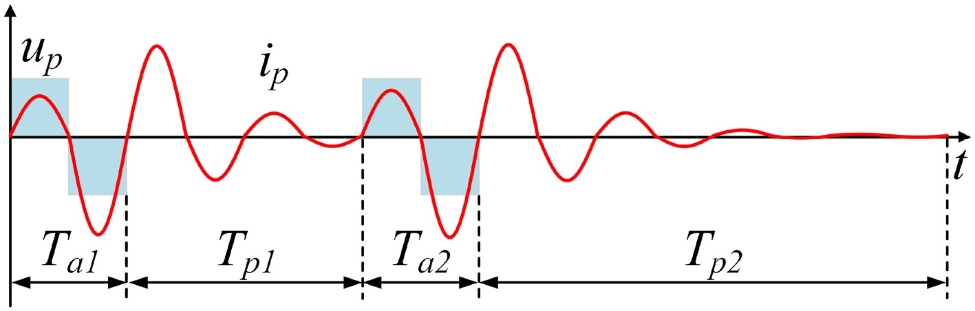
Figure 7.
Waveforms of inverter output voltage and current at N = 8 and m = 0.25.
Traditional PDM tends to concentrate energy pulses, leading to severe current fluctuations. APDM addresses this issue by subdividing resonant cycles and uniformly distributing energy pulses:
(1) A single resonant cycle in traditional PDM is subdivided into two equal-duration sub-cycles, each corresponding to an independent switching state ('1', '−1', or '0'). This subdivision breaks the concentrated energy distribution pattern within a single resonant cycle, allowing energy to be dispersed throughout the entire control cycle and avoiding sudden current surges caused by excessive energy injection within a single cycle.
(2) Guided by the principle of minimizing both the maximum continuous energy transfer time (Ta_max) and the maximum continuous non-energy transfer time (Tp_max), the optimal switching sequence Sw (N, m) is selected by traversing different pulse distribution combinations. This approach reduces current fluctuations at the sequence level, as demonstrated in Table 1.
Table 1. Switching sequences of the apdm with different N and m values.
N m Sw (N, m) 8 0.125 1000000−100000000 7 0.140 1000000−10000000 6 0.170 10000−1000000 5 0.200 10000−10000 4 0.250 100−10000 7 0.290 1000100−1000−100 3 0.330 100−100 8 0.375 100−10010100−10−100 5 0.400 100−10−10010 7 0.430 1010100−10−10−100 2 0.500 1−100 7 0.570 1010101−10−10−10−1 5 0.600 10101−10−10−1 8 0.625 101−10−1101−10−10−110 3 0.670 101−10−1 7 0.710 1−1101−10−11−10−110 4 0.750 1−1101−10−1 5 0.800 1−1101−11−10−1 6 0.830 1−1101−11−10−11−1 7 0.860 1−11−1101−11−10−1 8 0.875 1−11−11−1101−11−11−10−1 1 1.000 1−1 Additionally, traditional PDM carries the risk of DC component injection. The introduction of DC components causes deviation in the inverter output voltage, subsequently leading to system impedance imbalance. This constitutes a critical flaw for PT-WPT systems that rely on 'impedance symmetry' to achieve PT-symmetric operation. Impedance imbalance directly disrupts the 'gain-loss balance' of the PT-symmetric state, resulting in failure of the constant-power characteristic. Although half-wave PDM improves current fluctuations through sub-cycle division, DC components still persist within fixed control cycles, causing unbalanced switching loss and conduction loss of IGBT.
To address this issue, this paper adopts an adjustable control cycle strategy, selecting appropriate control cycles based on the pulse sequence to compensate for the limitations of fixed-cycle half-wave PDM. Furthermore, APDM employs a 'switching state combination constraint', allowing only combinations of three switching states—'1', '−1', and '0'—for power regulation, while prohibiting the use of unipolar pulses (e.g., only '1' or only '−1'). The introduction of the '0' state enables flexible adjustment of the total energy transfer by varying the proportion of '0' states to regulate pulse density without disrupting the symmetry of positive and negative pulses. For example, when reducing output power, the number of '0' states is increased instead of reducing pulses of a specific polarity, ensuring that within any control cycle, the number of '1' (positive voltage energy pulses) and '−1' (negative voltage energy pulses) remains equal. This 'strictly symmetric positive-negative pulse' design ensures that the voltage integral over the control cycle is zero, fundamentally eliminating DC components and preventing system impedance deviation.
Figure 8 shows the key waveforms for achieving zero-voltage switching. To realize ZVS, at the switching transition moment, the inverter output voltage first drops to zero, followed by the primary current crossing zero. The switching devices transition under zero-voltage conditions without voltage or current abrupt changes, ensuring the stability of the critical coupling coefficient of the PT-symmetric state without deviation. tps is defined as the time when the inverter output voltage polarity switches, and it is used as the minimum dead time td for IGBT to ensure ZVS implementation. When switching, the value of tps satisfies the following relationship:
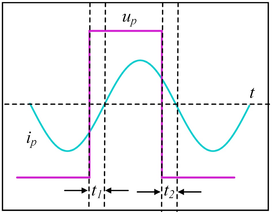
Figure 8.
Implementation process of ZVS.
$ {t}_{\textit{ps}}=\dfrac{1}{\omega }{\cos }^{-1}\left(1-\dfrac{2\omega {C}_{\textit{e}}{U}_{\textit{dc}}}{{I}_{\textit{p}\_ \textit{peak}}}\right) $ (18) where, ω is the angular frequency of the inverter switching frequency, Ce is the equivalent capacitance of the inverter (including IGBT parasitic capacitance and snubber capacitance), Udc is the DC bus voltage, and Ip_peak is the amplitude of the primary current.
However, the PT-WPT system automatically adjusts its operating frequency ω with variations in the coupling coefficient κ to maintain constant power output. A fixed dead time would lead to ZVS failure, resulting in increased switching losses and abrupt impedance changes, thereby disrupting the PT-symmetric state. To address this, the ZVS dead time for APDM must be customized based on the dynamic frequency and current characteristics of the PT system. This paper adopts a dynamic ZVS adaptation strategy to accommodate the automatic frequency regulation of PT systems. By real-time detection of the primary current via current sensors and calculating ω from the system resonant frequency f, the value of tps is derived using the formula. The dead time is then set as td = tps to prevent bridge arm shoot-through and stably achieve ZVS. This approach resolves the issue where traditional modulation with fixed dead time fails to adapt to the dynamic frequency variations in PT systems.
-
To verify the feasibility of integrating the proposed APDM with the PT-WPT system and to demonstrate its advantages in maintaining constant power, enabling flexible power regulation, and optimizing performance, an experimental prototype was constructed and tested. The hardware architecture, shown in Fig. 9, primarily consists of a DC power supply, a GaN full-bridge inverter, a PT-WPT main topology, a DSP, a control module, a load, and measurement equipment. The key parameters of the experimental prototype are listed in Table 2.
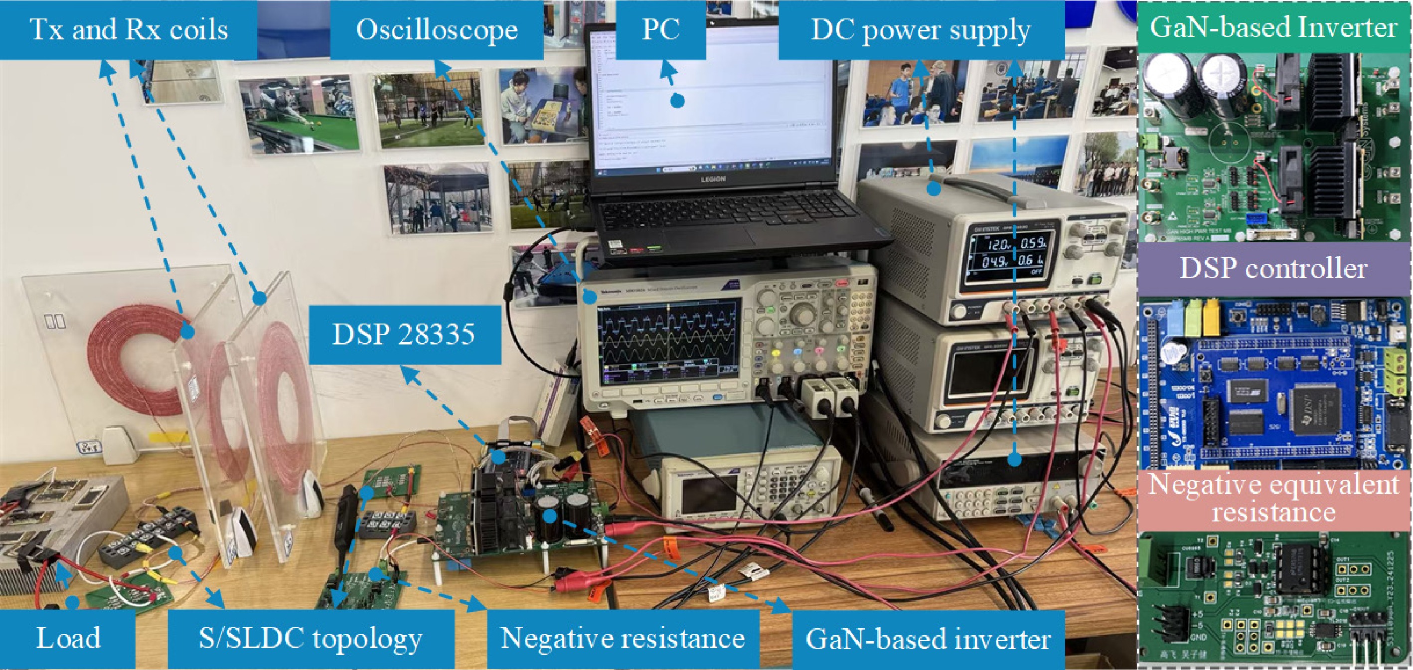
Figure 9.
Experimental prototype of the proposed S/SLDC higher-order PT-WPT system.
Table 2. Key parameters of prototype.
Item Value Inductance of transmitting coil (Lp) 140.1 μH Resistance of primary side (Rp) 0.4 Ω Capacitance of primary side (Cp) 18.08 nF Inductance of pickup coil (Ls) 60.39 μH Inductance of added inductor (Lr) 59.62 μH Capacitance of series capacitor (Cs1) 12.664 nF Capacitance of parallel capacitor (Cs2) 8.4427 nF Resistance of secondary side (Rs) 0.3 Ω Resistance of load (RL) 10 Ω System natural operating frequency (f0) 100 kHz Validation of expanded operational region and constant-power characteristic
-
The PT-WPT system exhibits constant output power independent of the coupling coefficient within the strong coupling region, while the introduction of modulation strategies may disrupt the 'gain-loss balance' of the PT-symmetric state. In this experiment, the APDM pulse density was fixed, and the coupling coefficient was varied by adjusting the distance between the transmitting and receiving coils to validate the constant-power characteristics and expanded operational range achieved by combining APDM with the S/SLDC topology.
Figure 10a shows the relationship between output power, efficiency, and coupling coefficient at a pulse density of m = 0.8. For the conventional S/S topology, power remains constant only within 60 mm (κc = 0.2630). In contrast, the S/SLDC topology adopted in this scheme significantly extends the constant-power region. When the transmission distance increases from 60 mm (κc = 0.2630) to 140 mm (κc = 0.0715), the output power with APDM remains stable at 75W with minimal fluctuation, and the system efficiency also remains largely unchanged. Figure 10b illustrates the relationship between the system operating frequency and the coupling coefficient at m = 0.8. As shown, the system operating frequency adjusts automatically, which is key to maintaining constant power in the PT-WPT system.
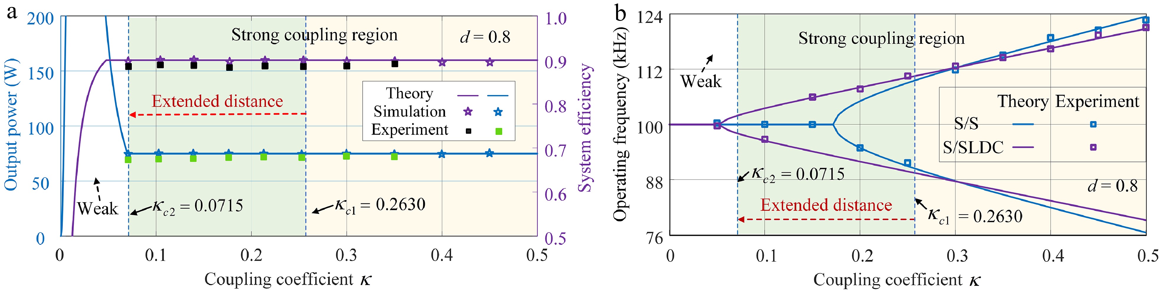
Figure 10.
Schematic diagram of output characteristics under m = 0.8. (a) Output power and transmission efficiency. (b) System operating frequency.
Furthermore, this paper analyzes the power loss of the PT-WPT system. In the PT-WPT system, the negative resistance characteristic of the component is realized by controlling the full-bridge inverter. Therefore, the loss of the negative resistance is essentially the loss of the inverter, with no other additional losses. In other words, similar to common inverter losses, the losses of the negative resistance primarily include the MOSFET losses. Consequently, the power loss of the PT-WPT system mainly comprises inverter loss and coil loss, which is also the main reason for the discrepancies in power and efficiency observed in the experiments.
As shown in Fig. 10, the system output power is maintained at 75 W, with efficiency consistently above 88%, and the total loss is approximately 9 W. Although there are slight fluctuations in the output power within the PT-symmetric region, the variation amplitude does not exceed 5%. These errors remain within an acceptable range and do not affect the main conclusions of this paper.
Figure 11 displays the waveforms at a pulse density of m = 0.8 and transmission distances of 40, 60, 80, and 100 mm. As observed from the waveforms, the primary current ip under APDM modulation maintains a sinusoidal characteristic without abrupt changes or interruptions. This is attributed to the innovative pulse distribution design of APDM, which subdivides resonant cycles and uniformly allocates energy pulses while ensuring strict symmetry between positive and negative pulses, thereby avoiding DC component injection that could disrupt the energy balance of the PT system. Similarly, the system output power and efficiency remain constant. This demonstrates that the synergistic combination of the proposed APDM and the S/SLDC topology not only expands the constant-power region but also ensures κ ≥ κc with low fluctuation characteristics, maintaining stable constant-power output.
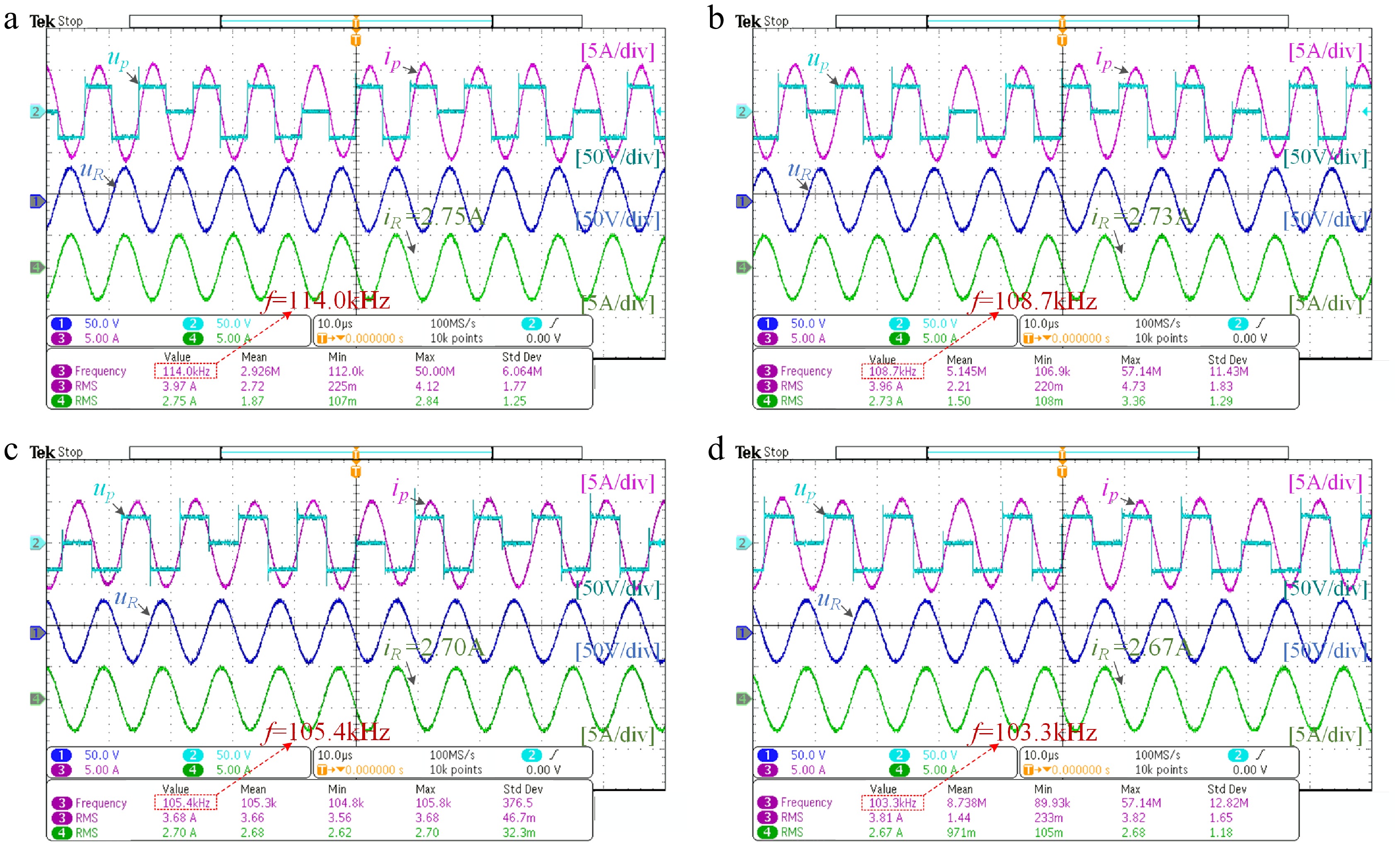
Figure 11.
Experimental waveforms at different transmission distances under m = 0.8. (a) d = 40 mm. (b) d = 60 mm. (c) d = 80 mm. (d) d = 100 mm.
Power regulation characteristics verification
-
The constant-power value of PT-WPT systems is traditionally fixed by topological parameters, making it difficult to meet dynamic power demands in scenarios such as drone applications (e.g., fast/slow charging switching). This experiment tested the output power and efficiency under different pulse densities at a transmission distance of 100 mm, as shown in Fig. 12. The results verify the power regulation capability of APDM without requiring any DC-DC converters throughout the process—achieved solely through primary-side APDM implementation.
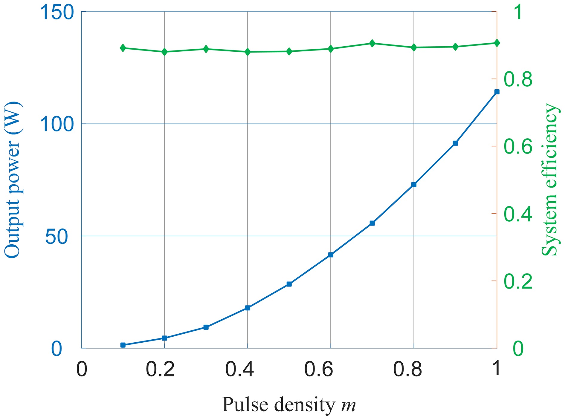
Figure 12.
Output power and efficiency under different pulse densities at 100 mm transmission distance.
As indicated by prior theoretical analysis, the output power exhibits a linear increasing relationship with the square of the pulse density, a trend clearly demonstrated in Fig. 12. When m = 0.1, the output power approaches zero; when m = 1, the power reaches its peak. This confirms that APDM enables precise regulation of energy injection duty cycles, achieving wide-range power adjustment to meet the requirements of different charging modes. The efficiency curve remains consistently around 90%, verifying the efficiency advantage of APDM across a broad power regulation range. Unlike conventional PDM, the proposed APDM reduces current ripple and avoids current interruption, thereby preventing the sharp efficiency drop that occurs in traditional methods when deviating from the optimal operating point. This gives APDM a significant efficiency advantage over conventional PDM in applications requiring wide-range power regulation, especially under light-load conditions.
Figure 13 displays the waveforms at a transmission distance of 100 mm for characteristic pulse densities of m = 0.8, 0.6, 0.4, and 0.2. These results validate the power regulation mechanism of the APDM: by adjusting the pulse density m, the energy injection per unit cycle is precisely controlled. Through sequence optimization, current stability is ensured, making it fully compatible with the primary-side control architecture of PT-WPT systems. Without requiring secondary-side feedback or additional hardware, flexible switching between different constant-power levels is achieved simply by modulating the pulse density m of the primary-side APDM, thereby extending the multi-scenario adaptability of PT-WPT systems.
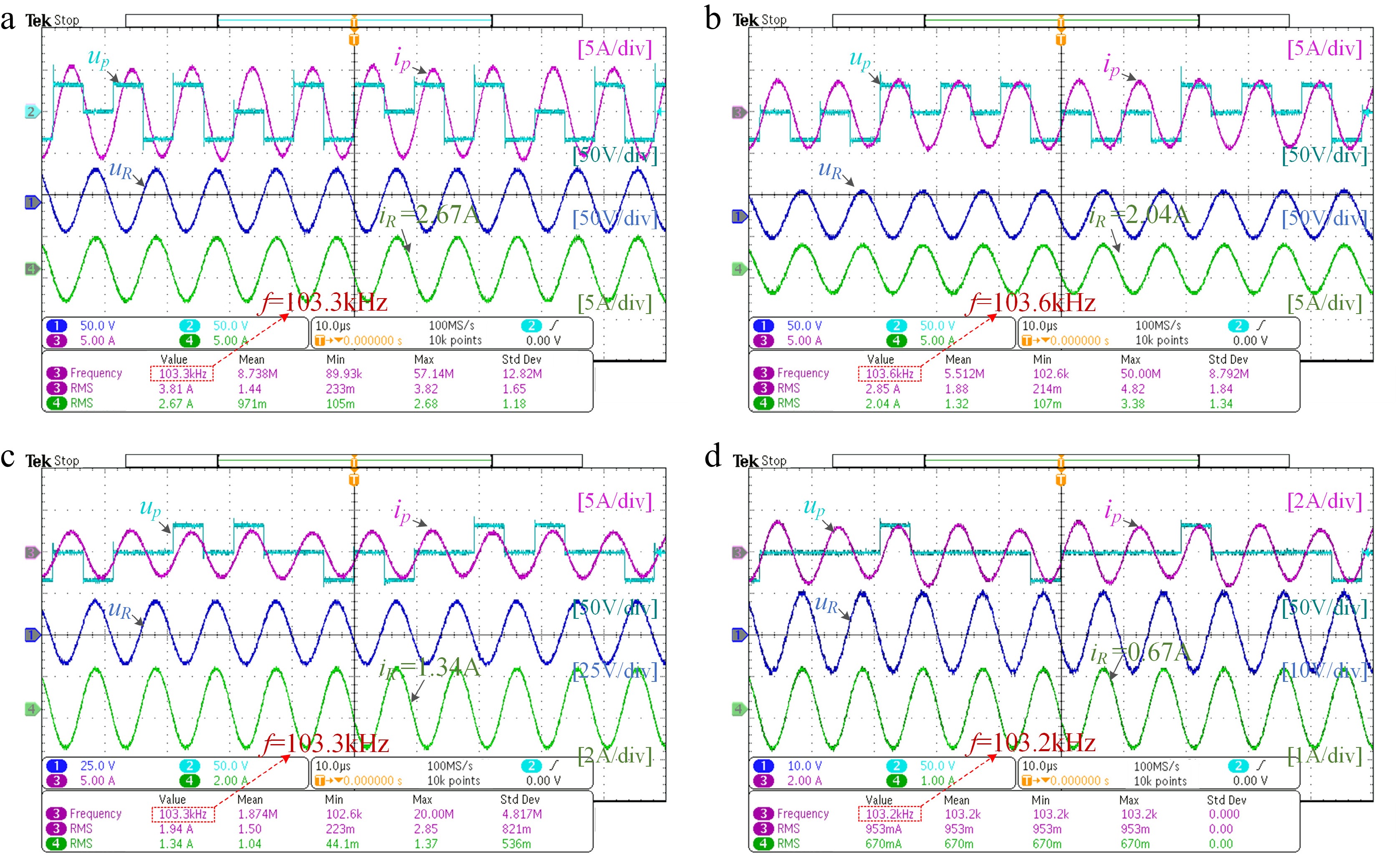
Figure 13.
Experimental waveforms under different pulse densities at 100 mm transmission distance. (a) m = 0.8. (b) m = 0.6. (c) m = 0.4. (d) m = 0.2.
To further verify the generality of this behavior, output characteristics were tested under different pulse densities at various transmission distances. Waveforms at m = 0.5 for 50 and 120 mm, and at m = 0.2 for 50 and 120 mm, are shown in Fig. 14. Comparing Fig. 14a and b, as well as Fig. 14c and d, it is observed that under the same pulse density, the primary voltage, primary current, secondary voltage, and secondary current waveforms maintain excellent sinusoidal shape and symmetry without significant distortion across different distances such as 50 and 120 mm. This indicates that APDM operates stably over multiple transmission distances without depending on a specific range, making it suitable for scenarios with varying drone flight heights. Furthermore, comparing Fig. 14a and c, as well as Fig. 14b and d, at the same transmission distance, the amplitudes of voltage and current increase with higher pulse density, resulting in synchronous growth in output power. This confirms that APDM can flexibly regulate power at different distances by adjusting the pulse density, meeting dynamic charging requirements.
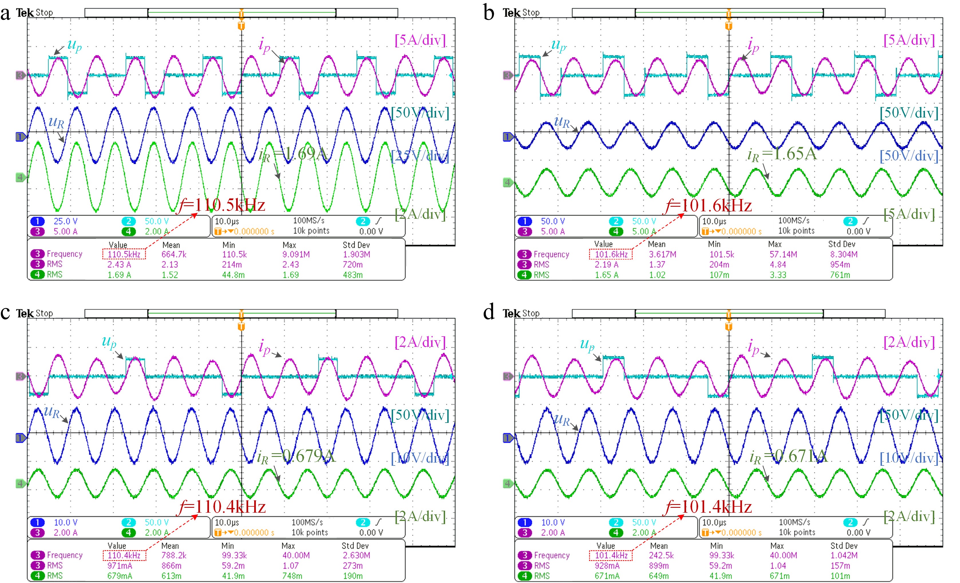
Figure 14.
Experimental waveforms at different distances and pulse densities. (a) m = 0.5, d = 50 mm. (b) m = 0.5, d = 120 mm. (c) m = 0.2, d = 50 mm. (d) m = 0.2, d = 120 mm.
ZVS reliability verification
-
Switching loss is a key factor affecting the efficiency of PT-WPT systems. Traditional PDM suffers from unstable ZVS implementation due to current fluctuations, especially in weak coupling scenarios. APDM addresses this issue via a dynamic dead-time strategy—calculating the dead time in real time based on the zero-crossing moment of the primary current—which avoids the 'premature turn-off' or 'delayed turn-on' problems associated with fixed dead time. This ensures that the current maintains the corresponding polarity when the voltage polarity switches, enabling reliable ZVS. Figure 15 illustrates the ZVS realization process at m = 0.8 and d = 90 mm.
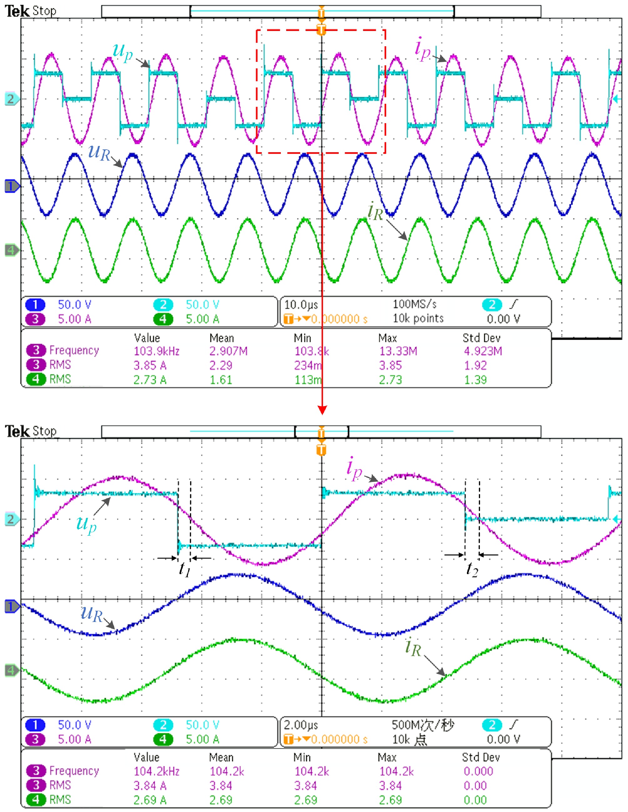
Figure 15.
ZVS implementation process at m = 0.8 and d = 90 mm.
Current ripple analysis
-
Conventional PDM exhibits abrupt current surges and drops, introducing significant non-resonant frequency components. This not only increases coil losses but also jeopardizes the safety of power devices. The asymmetric pulse distribution in traditional PDM causes uneven energy injection, leading to current spikes during pulse segments and sharp declines during zero-pulse intervals. In contrast, APDM achieves smooth energy injection through 'resonant cycle subdivision' and 'uniform pulse interpolation', confining current peak fluctuations within a narrow range.
Figure 16 shows the experimental waveforms under low pulse densities such as m = 0.3, 0.2, and 0.1 at transmission distances of d = 100 mm and 60 mm. It can be observed that even under such extremely low pulse densities, the proposed system still maintains excellent output characteristics with minimal fluctuations in the inverter output current and no interruption occurring. This experiment demonstrates that APDM, without relying on additional hardware, can effectively address the core drawback of high current ripple in traditional PDM through control-layer sequence optimization, thereby ensuring stable and efficient operation of the PT-WPT system.
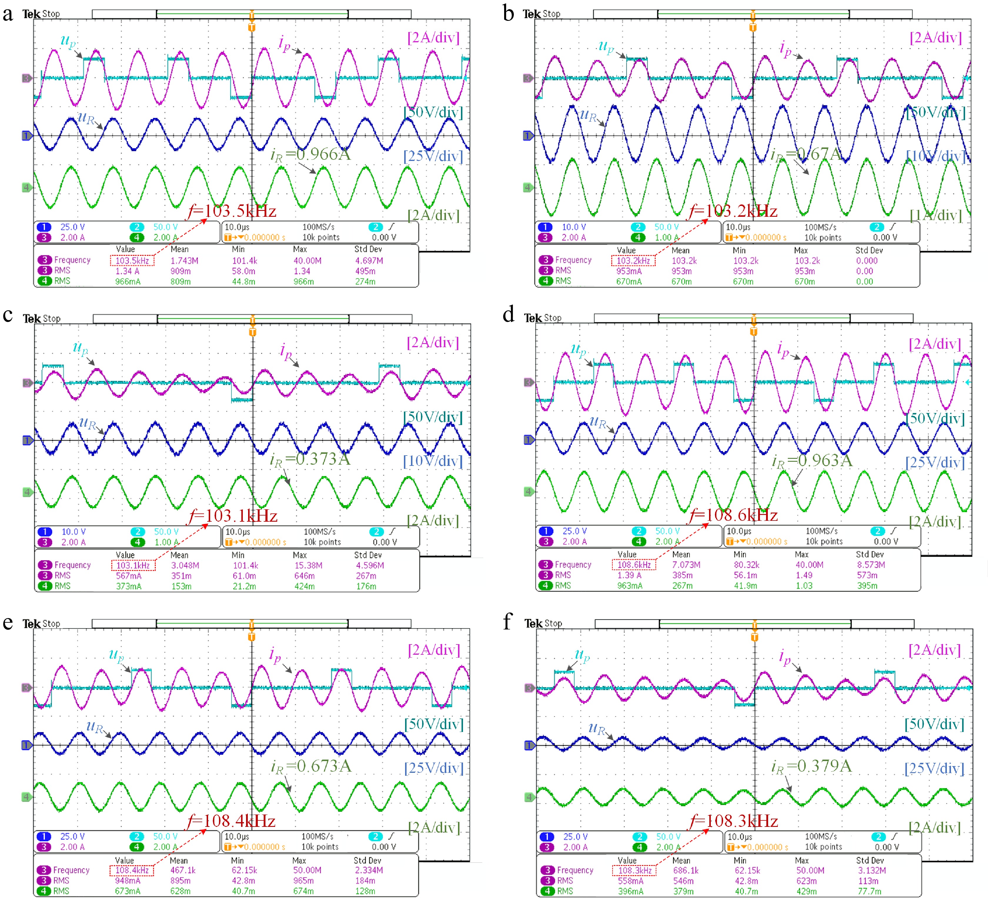
Figure 16.
Experimental waveform with low pulse density. (a) d =100 mm, m = 0.3. (b) d = 100 mm, m = 0.2. (c) d = 100 mm, m = 0.1. (d) d = 60 mm, m = 0.3. (e) d = 60 mm, m = 0.2. (f) d = 60 mm, m = 0.1.
Compared with other wireless power transmission systems
-
To highlight the advantages of the proposed APDM scheme for PT-WPT systems, Table 3 presents a comparative analysis between this work and existing wireless power transfer power regulation methods. The salient advantage of the proposed APDM is its capability to achieve wide-range power regulation without disrupting PT symmetry, while maintaining efficiency above 88% even under light-load conditions, offering high system flexibility. This makes it particularly suitable for drone in-flight charging applications.
Table 3. Comparative analysis between the proposed system and others.
Ref. Scheme PT-symmetry maintained? Power regulation? High system flexibility ZVS Frequency (kHz) Output power (W) Transfer efficiency [14] PWM Yes No Good No 100 75 87.5% [19] DC-DC No Yes Unexpected No 85 1 − [20] PFM Yes Yes Unexpected Yes 200 41.8 86.4% [23] PDM No Yes Unexpected Yes 85 787.5 80%–93.3% [27] PWM Yes No Unexpected No 200 50 90.8% This paper APDM Yes Yes Good Yes 100 112 88% Compared to incorporating an additional DC-DC converter[19], the proposed solution in this paper does not increase system complexity, cost, weight, or introduce additional losses. In contrast to conventional PDM[23], the APDM avoids the injection of DC components that would disrupt PT symmetry. When compared to common PT-WPT systems[14,27], the proposed scheme can maintain constant output power while achieving flexible power regulation and realizing ZVS. Furthermore, relative to other solutions, the system presented in this paper offers greater flexibility, featuring two additional degrees of freedom (λ and Lr) for adjusting and extending the constant charging power range. By optimizing the pulse sequences and employing half-wave subdivision, it effectively reduces current ripple and DC bias, achieving higher efficiency and thus providing superior performance for in-flight drone charging. Consequently, the proposed solution demonstrates greater advantage due to its wider constant power range and efficient, flexible power regulation.
-
This paper addresses the challenge of fixed constant-power output in parity-time-symmetric wireless power transfer systems, which struggle to meet dynamic power demands, by proposing a control strategy that integrates autonomous pulse density modulation with PT-WPT systems. Through theoretical analysis and experimental validation, the following conclusions are drawn:
(1) The proposed APDM modulation scheme based on the PT-WPT system enables flexible regulation of constant-power output while maintaining the PT symmetry of the system. By adjusting the pulse density, the system can deliver different levels of constant power within the strong coupling region, effectively overcoming the limitation of fixed power output in conventional PT-WPT systems.
(2) APDM technology optimizes the switching sequence distribution, significantly reducing output current fluctuations and improving the quality of power transfer. Simultaneously, the scheme reliably achieves zero-voltage switching operation, reducing switching losses and enhancing the overall system efficiency.
(3) This control strategy eliminates the need for complex feedback control systems or secondary-side communication devices. It is highly compatible with the primary-side control architecture of PT-WPT systems, retaining both the robustness of PT symmetry against coupling variations and the low-ripple, high-efficiency characteristics of APDM.
This study provides an effective solution for flexible power regulation in multi-scenario applications of PT-WPT systems, significantly expanding their potential in fields such as drones and mobile devices with variable power demands. It offers new insights for the practical development of wireless power transfer technology. Future work will further explore the application of the APDM strategy to multi-load/dynamic load wireless power supply systems and develop low-complexity real-time optimization algorithms tailored for APDM, thereby enhancing the flexibility of PT-WPT systems.
This work was supported by the find of Scientific Research Project of Tianjin Education Commission (Grant No. 2022KJ114).
-
The authors confirm their contributions to the paper as follows: study conception and design: Qin Y, Gu Y, Gao F; data collection: Gao F, Gu Y; analysis and interpretation of results: Gao F, Qin Y, Zhang Z, Gu Y; draft manuscript preparation: Gao F. All authors reviewed the results and approved the final version of the manuscript.
-
All data generated or analyzed during this study are included in this published article.
-
The authors declare that they have no conflict of interest.
- Copyright: © 2026 by the author(s). Published by Maximum Academic Press, Fayetteville, GA. This article is an open access article distributed under Creative Commons Attribution License (CC BY 4.0), visit https://creativecommons.org/licenses/by/4.0/.
-
About this article
Cite this article
Gao F, Qin Y, Gu Y, Zhang Z. 2026. Autonomous pulse density modulation for parity-time-symmetric WPT system with flexible power regulation. Wireless Power Transfer 13: e006 doi: 10.48130/wpt-0025-0035 

Autonomous pulse density modulation for parity-time-symmetric WPT system with flexible power regulation
- Received: 09 September 2025
- Revised: 29 October 2025
- Accepted: 04 December 2025
- Published online: 27 February 2026
Abstract: Parity-time symmetric wireless power transfer (PT-WPT) systems exhibit fixed constant-power output, which fails to meet the power regulation requirements for applications such as drone wireless in-flight charging. To address this limitation, this paper proposes an autonomous pulse density modulation (APDM) strategy. Within the strong-coupling region, the constant-power level can be flexibly regulated by adjusting the pulse density without disrupting the 'gain-loss balance' of the PT-symmetric state, thereby adapting to multi-scenario power demands. First, a high-order primary-series (S) and secondary-single-inductor-double-capacitor (SLDC) topology is designed to effectively expand the constant-power region of the system. Then, an APDM strategy with uniform energy injection is proposed, which optimizes pulse sequence distribution to suppress output current fluctuation and enable full-range zero-voltage switching (ZVS). Experimental results demonstrate that the system maintains the robustness of PT symmetry against coupling fluctuations while achieving autonomous and flexible power regulation across the designed pulse density range, with efficiency maintained at 88% and stable ZVS implementation. These results confirm the superiority of the proposed solution in power regulation, significantly expanding the application potential of PT-WPT systems in multi-power-demand scenarios such as drones.