












-
The wireless charging problem of intelligent pallets has received attention as intelligent pallets are frequently used in reality. Traditionally, the chip module of an intelligent pallet required a high-capacity and large-sized battery to ensure sufficient service life, which increased the system cost. The adoption of wireless charging can reduce the required battery capacity and size while improving operational safety.
An intelligent pallet wireless charging schematic is shown in Fig. 1. A large-sized coil can be installed on the pallet, as the available area is not constrained, while a small-sized coil is integrated into the onboard chip module. The large coils form the power transmission channel, ensuring reliable power delivery to each module and enhancing both the transmission efficiency and distance.
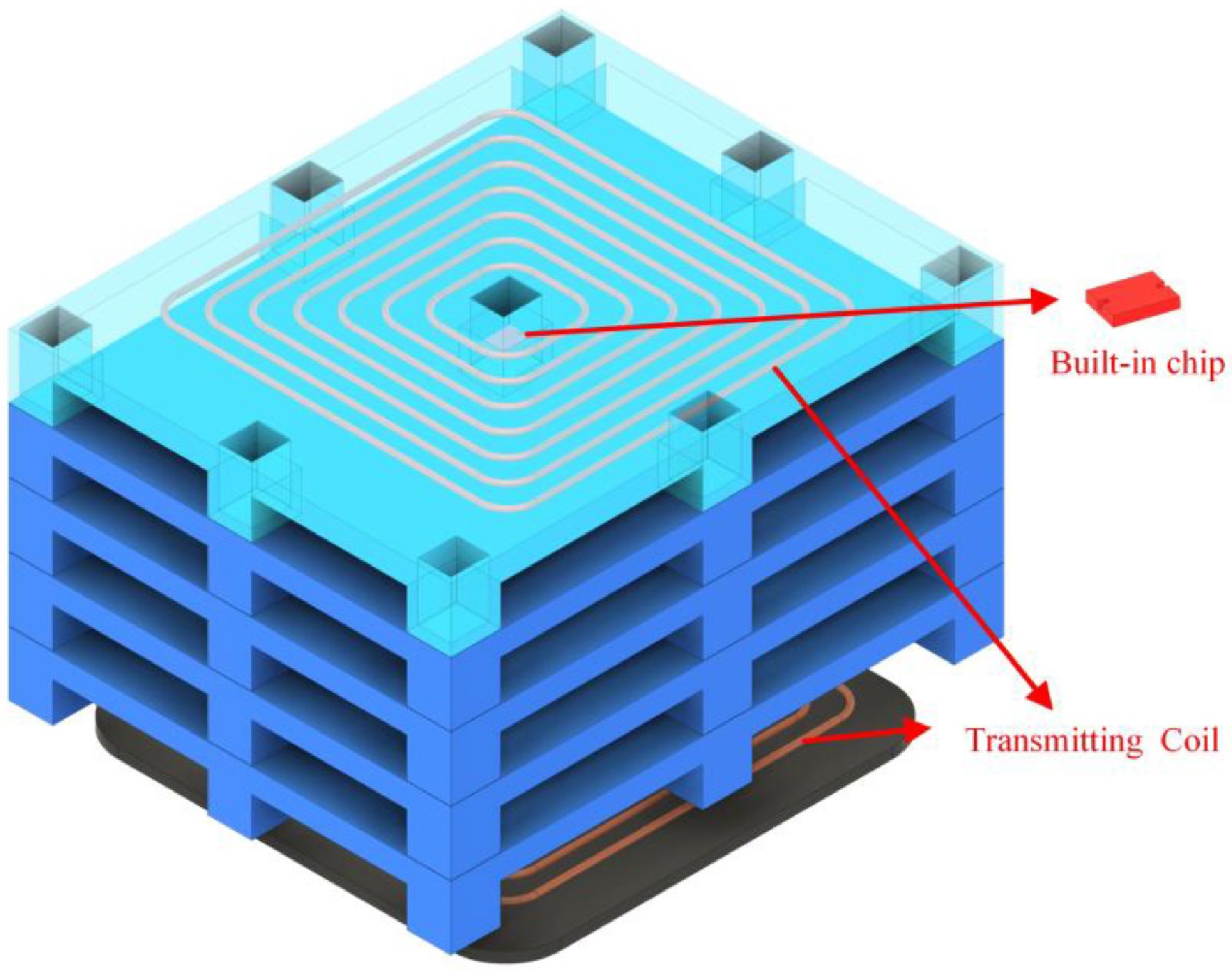
Figure 1.
Intelligent pallet placement schematic.
In previous studies, due to the wireless charging for multiple loads, the method of multiple receiving loops to directly pick up power from the transmitting loop is usually adopted. Such systems have been shown to achieve compact configurations while enabling controllable power flow among different loads[1]. To further improve adaptability, customized resonant structures have been introduced to support charging of various types of receiving loops with different load ratings, allowing each receiver to pick up sufficient power[2]. In addition, optimal drive current derivation methods have been studied to maximize system efficiency in multi-receiver scenarios, particularly when real-time coupling information is unavailable[3]. Multi-receiver WPT systems have been modeled to identify operating frequencies that enable load-independent output voltage. It has been demonstrated that load output independence can be achieved at two specific frequencies under varying coupling coefficients[4]. For the application of intelligent pallet wireless charging, due to the requirement for the power consistency of each pallet, this method cannot be applied.
In addition, multi-frequency operation has emerged as an important approach for multi-load WPT. By allowing each receiving loop to operate at a distinct frequency, independent power delivery to multiple loads can be achieved. Based on this concept, power flow control among multiple receivers has been realized by assigning different resonant frequencies to the receiving loops. It has been demonstrated that the maximum efficiency occurs at the receiving loop resonant frequency, independent of the transmitting loop resonant frequency[5]. Dual-frequency inverters have also been investigated to enable selective power distribution, including multi-relay configurations employing shared power channels and dual-frequency inverters to achieve CC output for multiple loads[6]. Moreover, frequency bifurcation techniques have been introduced to support simultaneous power transmission to loads at different frequencies, leading to improved transfer efficiency[7]. To further enhance system performance, multi-frequency resonant networks have been developed, allowing power components at different frequencies to be selectively delivered to corresponding loads[8]. Multichannel one-to-multiple WPT systems have also been proposed, in which independent power transmission paths are established for different receivers and regulated through inverter duty-cycle control[9]. However, for intelligent pallet wireless charging applications, these multi-frequency methods are not suitable due to their high control complexity and limited charging scalability.
Furthermore, there are some studies on the coil structure. Optimized transmitter designs based on multi-objective genetic algorithms have been shown to improve coil parameters and provide a novel one-to-many WPT idea[10].
In previous studies, various multi-coil structures have been extensively explored for multi-relay WPT systems. Comparing two-coil WPT systems, operating in an over-coupled state has been shown to enhance both transmission efficiency and stability[11]. The relationship between the quantity of relay coils and the achievable optimal efficiency has also been studied[12]. To further improve system robustness, hybrid relay topologies have been introduced to enhance mutual inductance and tolerance of coil relative position deviation[13]. In addition, the impact of cross-coupling among multiple relay coils has been analyzed, and corresponding coupling mechanism design methods have been refined to improve efficiency in a multi-relay WPT system[14]. Two-layer optimal control schemes based on pulse-width and pulse-frequency have been demonstrated to enable maximum efficiency tracking as well as load-independent CC and CV output[15]. Parity–time (PT) symmetry has been used to realize novel multi-relay WPT systems capable of maintaining stable output power and efficiency over a certain transmission distance without control or feedback[16]. The PT-symmetry conditions have been relaxed to establish generalized WPT configurations, and the transmission distance of the system is improved[17].
In this paper, a multi-stage WPT system with a special resonant compensation structure is proposed to charge the built-in battery of the intelligent pallet. The main contributions are summarized as follows. First, the circuit topology of the proposed multi-stage WPT system is described, and the cross-coupling phenomena among different stages are investigated to establish a corresponding coupling mechanism model. Then, the effects of the resonant parameters of the transmitting loops on the inverter output voltage and overall system efficiency are examined, based on which a parameter optimization strategy is developed. Finally, the proposed approach is verified through experiments.
-
The schematic diagram of the multi-stage WPT system with n stages is shown in Fig. 2. The system consists of three parts: primary loop, relay loop, and load loop. In the primary loop, the system includes DC power Udc, a full-bridge inverter (S11−S14), and an LCC topology structure, which consists of Cp, C0, and transmitting coil L00. In the relay loop, the power is picked up from the last stage by Li2 and transmitted to the next stage by Li1 (i = 1, 2 ··· n). Ci1, Ci2, and Ci3 are resonant capacitors. The S topology is used in the load loop, which consists of Lsi, Csi, and Ri. The mutual inductances and coupling coefficients are: between L00 and L11 are defined as M00_11 and k00_11; between Li2 and L(i+1)1 are Mi2_(i+1)1 and ki2_(i+1)1; between Li2 and Lsi are Mi2_si and ki2_si.
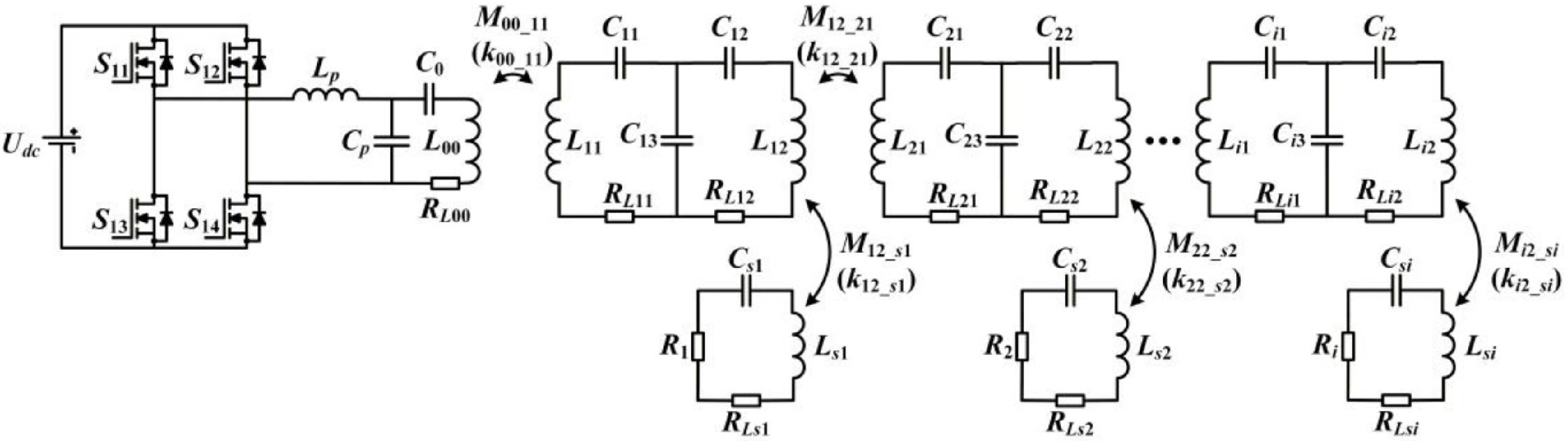
Figure 2.
Proposed multi-stage WPT system.
The operating frequency of the full-bridge inverter in the primary loop is f, and its angular frequency is ω(ω = 2πf). When the inductance and capacitance in the constructed topology meet Eq. (1), the equivalent impedance of each circuit is pure resistance.
$ \begin{cases} {L}_{p}{C}_{p}={L}_{si}{C}_{si}=\left({L}_{00}-{L}_{p}\right){C}_{0}=\dfrac{1}{{\omega }^{2}}\\ j\omega {L}_{i1} + \dfrac{1}{j\omega {C}_{i1}} + \dfrac{1}{j\omega {C}_{i3}}=0\\ j\omega {L}_{i2} + \dfrac{1}{j\omega {C}_{i2}} + \dfrac{1}{j\omega {C}_{i3}}=0 \end{cases} $ (1) Analysis of coil cross-coupling and output performance
-
Load-independent output characteristics at each stage contribute to improved output stability in the proposed WPT system.
Due to the complexity of the analysis of the coupling relationship of all stages, Fig. 3 shows a system containing two stages. The impact of cross-coupling on the output voltage is analyzed, which considers all the coupling relationships between the stages in the system. In Fig. 3, when the inductance and capacitance meet Eq. (1), the KVL equation is Eq. (2).
The coil resistance can be neglected, as: RLi1 = RLi2 = RL(i+1)1 = RL(i+1)2 = RL(i+1)2 = RLsi = RLs(i+1) = 0. According to Eq. (2), the currents Ii2 and I(i+1)2 in transmitting coils of the relay loop can be expressed as Eq. (3):
$ \begin{aligned}\left[\begin{array}{l} {\dot{U}}_{i}\\ 0\\ 0\\ 0 \end{array}\right]&=\left[\begin{matrix} {R}_{Li1} & -\dfrac{1}{j\omega {C}_{i3}} & j\omega {M}_{i1\_ si} & j\omega {M}_{i1\_ (i + 1)1} & j\omega {M}_{i1\_ (i + 1)2} & 0\\ -\dfrac{1}{j\omega {C}_{i3}} & {R}_{Li2} & j\omega {M}_{i2\_ si} & j\omega {M}_{i2 + (i + 1)1} & j\omega {M}_{i2\_ (i + 1)2} & j\omega {M}_{i2\_ s(i + 1)}\\ j\omega {M}_{i1\_ (i + 1)1} & j\omega {M}_{i2 + (i + 1)1} & j\omega {M}_{si\_ (i + 1)1} & {R}_{L(i + 1)1} & -\dfrac{1}{j\omega {C}_{(i + 1)3}} & j\omega {M}_{(i + 1)2\_ s(i + 1)}\\ j\omega {M}_{i1\_ (i + 1)2} & j\omega {M}_{i2\_ (i + 1)2} & 0 & -\dfrac{1}{j\omega {C}_{(i + 1)3}} & {R}_{L(i + 1)2} & j\omega {M}_{(i + 1)2\_ s(i + 1)} \end{matrix} \right]\left[\begin{array}{l} {\dot{I}}_{i1}\\ {\dot{I}}_{i2}\\ {\dot{I}}_{i3}\\ \begin{array}{l} {\dot{I}}_{(i + 1)1}\\ {\dot{I}}_{(i + 1)2}\\ {\dot{I}}_{(i + 1)3} \end{array} \end{array}\right]\\ & \end{aligned} $ (2) $ \begin{cases} {\dot{I}}_{i2}=\dfrac{{C}_{i3}\omega \left(\left(AC{C}_{(i + 1)3}{\omega }^{7}-(2D-F){\omega }^{5}2{I}_{i3} + j{\dot{U}}_{i}B{\omega }^{4}\right)C_{(i + 1)3}^{2} + E{C}_{(i + 1)3}{\omega }^{3}-\omega {M}_{i1\_ si}{I}_{i3}-j{\dot{U}}_{i}\right)}{A{C}_{i3}C_{(i + 1)3}^{2}{\omega }^{8}-\left({C}_{(i + 1)3} + {C}_{i3}\right)B{C}_{(i + 1)3}{\omega }^{4} + 1}\\ {\dot{I}}_{(i + 1)2}=\dfrac{{\omega }^{2}{C}_{(i + 1)3}\left({\omega }^{5}C_{(i + 1)3}^{2}{C}_{i3}\left(Aj{\dot{U}}_{i}{M}_{i2\_ (i + 1)1}-\omega AG\right) + H{M}_{i2\_ (i + 1)1}{\dot{I}}_{i3}{C}_{(i + 1)3}{\omega }^{2}-{M}_{i1\_ si}{\dot{I}}_{(i + 1)3}-{M}_{si\_ (i + 1)1}{\dot{I}}_{i3}\right)}{A{C}_{i3}C_{(i + 1)3}^{2}{\omega }^{8}-\left({C}_{i3} + {C}_{(i + 1)3}\right)B{C}_{(i + 1)3}{\omega }^{4} + 1}. \end{cases} $ (3) 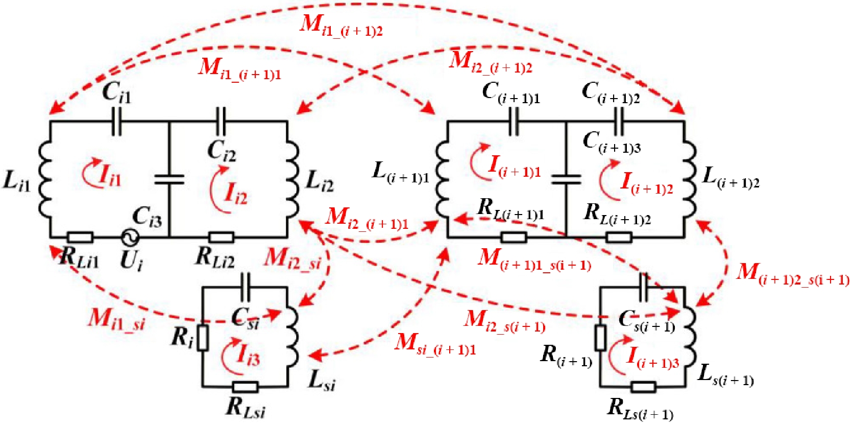
Figure 3.
Cross-coupling relationships of neighboring stages.
where, A–H are:
$ \begin{cases} A={M}_{i1\_ (i + 1)1}{M}_{i2\_ (i + 1)2}-{M}_{i1\_ (i + 1)2}{M}_{i2\_ (i + 1)1}\\ B={M}_{i1\_ (i + 1)1}{M}_{i2\_ (i + 1)2} + {M}_{i1\_ (i + 1)2}{M}_{i2\_ (i + 1)1}\\ C={\dot{I}}_{i3}{M}_{i1\_ (i + 1)2}{M}_{s1\_ (i + 1)1} + {\dot{I}}_{(i + 1)3}{M}_{i1\_ (i + 1)2}{M}_{i1\_ si}-{\dot{I}}_{(i + 1)3}{M}_{i1\_ (i + 1)1}{M}_{i2\_ si}\\ D={\dot{I}}_{i3}{M}_{i1\_ (i + 1)1}{M}_{i1\_ (i + 1)2}{M}_{i2\_ si} + {\dot{I}}_{(i + 1)3}{M}_{i1\_ (i + 1)1}{M}_{i1\_ (i + 1)2}{M}_{i2\_ s(i + 1)}\\ E={\dot{I}}_{i3}{M}_{i1\_ (i + 1)2}{M}_{s1\_ (i + 1)1} + {\dot{I}}_{(i + 1)3}{M}_{i1\_ (i + 1)2}{M}_{i1\_ si} + {\dot{I}}_{(i + 1)3}{M}_{i1\_ (i + 1)1}{M}_{i2\_ si}\\ F={\dot{I}}_{i3}{M}_{i1\_ (i + 1)2}{M}_{i2\_ (i + 1)1}{M}_{i1\_ si} + {\dot{I}}_{i3}{M}_{i1\_ (i + 1)1}{M}_{i2\_ (i + 1)2}{M}_{i1\_ si}\\ G={\dot{I}}_{i3}{M}_{i1\_ (i + 1)1}{M}_{i2\_ si}-{\dot{I}}_{i3}{M}_{i2\_ (i + 1)1}{M}_{i1\_ si} + {\dot{I}}_{(i + 1)3}{M}_{i1\_ (i + 1)1}{M}_{i2\_ s(i + 1)}\\ H={\dot{I}}_{i3}{M}_{i1\_ (i + 1)2}{M}_{si\_ (i + 1)1} + {\dot{I}}_{(i + 1)3}{M}_{i1\_ (i + 1)2}{M}_{i1\_ si}-{\dot{I}}_{(i + 1)3}{M}_{i1\_ (i + 1)1}{M}_{i2\_ si}. \end{cases} $ (4) It can be seen from Eq. (3) that if Mi1_(i + 1)1 = 0, Msi_(i + 1)1 = 0, the current Ii2 and I(i + 1)2 are:
$ \begin{cases} {\dot{I}}_{i2}=\dfrac{j\omega {C}_{i3}{\dot{U}}_{i}}{{\omega }^{4}{M}_{i1\_ (i + 1)2}{M}_{i2\_ (i + 1)1}{C}_{i3}{C}_{(i + 1)3}-1}\\ {\dot{I}}_{(i + 1)2}=\dfrac{-j{\omega }^{3}{M}_{i2\_ (i + 1)1}{C}_{i3}{C}_{(i + 1)3}{\dot{U}}_{i}}{{\omega }^{4}{M}_{i1\_ (i + 1)2}{M}_{i2\_ (i + 1)1}{C}_{i3}{C}_{(i + 1)3}-1}. \end{cases} $ (5) It can be seen from above analysis, if the following conditions are satisfied, then the current in relay loop is independent of load and load output is independent of load variations.
(1) Mi1_(i + 1)1 = 0, Msi_(i + 1)1 = 0.
(2) ω4Mi1_(i + 1)2Mi2_(i + 1)1Ci3C(i + 1)3 − 1 ≠ 0.
In addition, if the above conditions are satisfied by the system, according to Fig. 3, the output voltage of the loads are:
$ \begin{cases} {\dot{U}}_{Ri}=\dfrac{-{\omega }^{2}{M}_{i2\_ si}{C}_{i3}{\dot{U}}_{i}}{{\omega }^{4}{M}_{i1\_ (i + 1)2}{M}_{i2\_ (i + 1)1}{C}_{i3}{C}_{(i + 1)3}-1}\\ {\dot{U}}_{R(i + 1)}=\dfrac{{\omega }^{4}{M}_{i2\_ (i + 1)1}{M}_{(i + 1)2\_ s(i + 1)}{C}_{i3}{C}_{(i + 1)3}{\dot{U}}_{i}}{{\omega }^{4}{M}_{i1\_ (i + 1)2}{M}_{i2\_ (i + 1)1}{C}_{i3}{C}_{(i + 1)3}-1} \end{cases} $ (6) Equation (6) demonstrates that, under the stated conditions, the load voltage is decoupled from both the relay-loop current and the remaining loads.
According to the above analysis, the stable power can be supplied to both the load and the next relay loop under the proposed conditions. Accordingly, Fig. 4a illustrates that the coupling mechanism is devised to satisfy these conditions in the proposed system. By introducing a magnetic core between the two facing coils, the magnetic flux is guided along a low-reluctance path, which reduces the undesirable mutual inductance between coils[18−22]. In Fig. 4b, the magnetic flux density distribution obtained from COMSOL confirms that the magnetic core confines the magnetic field.
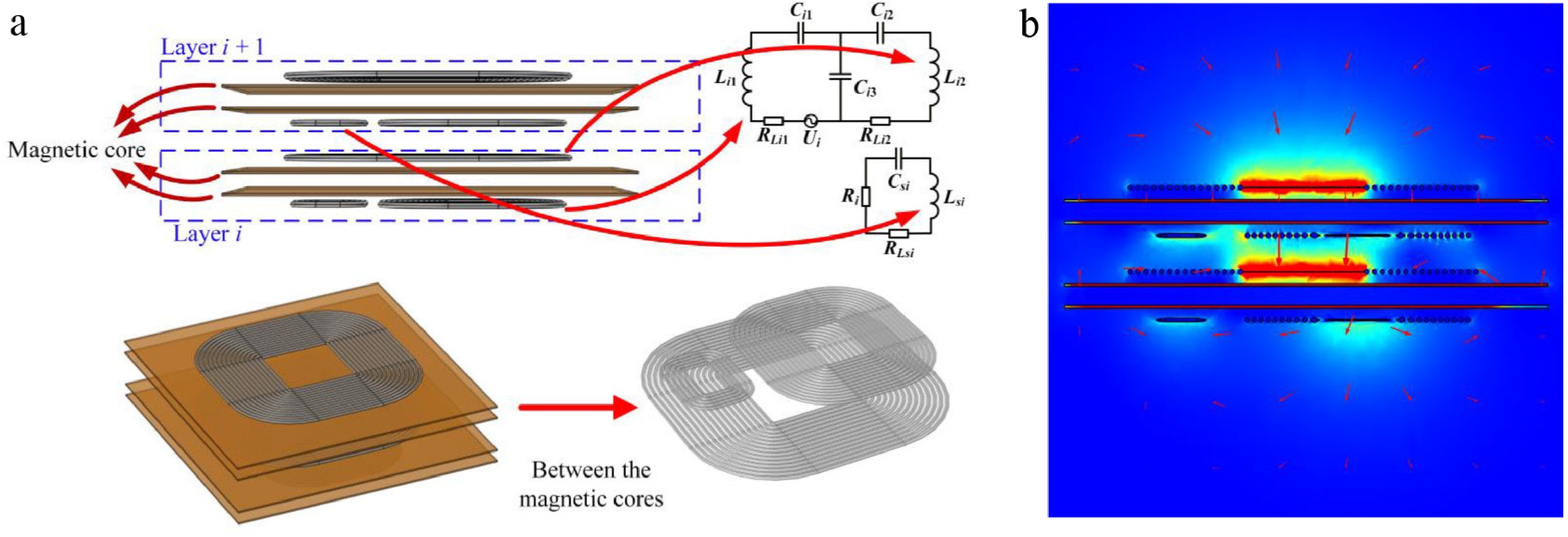
Figure 4.
Structure of the proposed decoupling model. (a) Coupling mechanism model. (b) Magnetic flux density distribution.
The mutual inductances shown in Fig. 3 are obtained from COMSOL magnetic field simulations and summarized in Table 1. The results indicate that the coupling coefficients that require decoupling are reduced by the magnetic core, which demonstrates the efficacy of the proposed decoupling method and ensures stable and independent power transfer in the system.
Table 1. Coupling coefficients.
Parameter Value Parameter Value ki1_(i+1)1 0.0022 ki2_si 0.1012 ksi_(i+1)1 0.0014 ki2_(i+1)1 0.2167 ki1_si 0.0141 ki2_s(i+1) 0.0037 ki1_(i+1)2 0.0012 ki2_(i+1)2 0.014 -
Due to the system including multiple stages, efficiency can be influenced by the parameters offset of each stage. In actual operation, the system will be affected by many non-ideal factors, which will decrease efficiency. The unreasonable design of LCC resonant inductance (Lp) is a major influencing factor, which will impact the resonant network quality factor, increase the switching loss, and decrease the efficiency. To enhance the system efficiency and overall performance, a parameter optimization method is introduced.
Analysis of voltage distortion under non-ideal parameter conditions
-
Taking the two-load case as an example, parameter offsets and MOSFET on-resistance are considered to model and analyze the mechanism of voltage distortion. Figure 5 illustrates the equivalent model of the two-load system. The DC power supply and the full-bridge inverter are represented by an AC voltage source and an equivalent resistance Rcom. The load loop shown in Fig. 2 is equivalent to Req in the relay circuit, thereby reducing the overall system complexity.
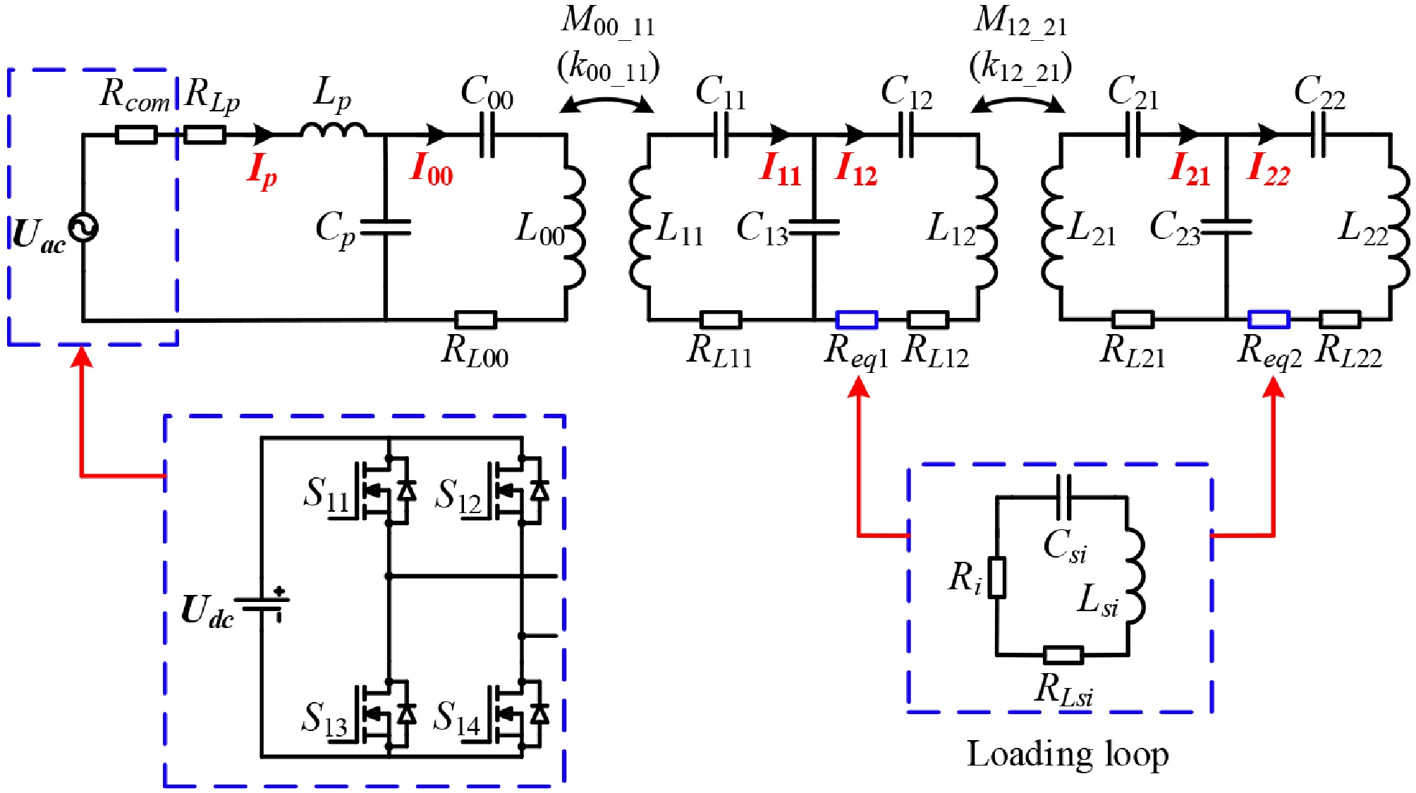
Figure 5.
Double loads equivalent system circuit.
The full-bridge inverter output voltage is composed of multiple harmonics. The inverter voltage Uac is shown in Eq. (7):
$ \begin{cases} {U}_{ac}\left(t\right)\text=\begin{cases} \begin{matrix} {U}_{dc} & 0 \lt tf-[tf] \lt 0.5\\ 0 & {\mathrm{others}} \end{matrix} \\ \begin{array}{ll} -{U}_{dc} & 0.5 \lt tf-[tf] \lt 1 \end{array} \end{cases} =\lim \limits_{k\rightarrow \infty }\displaystyle \sum\limits_{k=1}^{k}{U}_{k}\\ {U}_{k}\left(t\right)=\begin{array}{ll} \dfrac{4{U}_{dc}}{\pi }\cdot \dfrac{1}{2k-1}\cdot \sin \left((2k-1)\cdot 2\pi ft\right) & k=1,2,3\cdots \end{array} \end{cases} $ (7) t is time, f is inverter frequency, [] denotes rounding; Uk represents the corresponding harmonic component in the Fourier series of the inverter voltage. The full-bridge inverter output, Uac, is modeled as an ideal square wave. In the previous studies, the on-resistance of the MOSFET is overlooked, which will influence the accuracy of the efficiency analysis. The following will analyze the efficiency, and the above factors are considered. Due to the convenience of analysis, the stage parameters will use the following parameters.
Table 2 displays the parameters utilized by the system and meets the conditions of Eq. (8). On the basis of the calculation of Eq. (1), all resonant capacitors are added with a ± 1% random error to make the system more suitable for the actual working application.
Table 2. System parameters.
Parameter Value Parameter Value f 100 kHz Rcom 0.1 Ω Udc 100 V RLp 0.07 Ω Lp 46 μH RL00 0.5 Ω L00 100 μH Req 5 Ω $ \begin{cases} {C}_{p}={C}_{13}={C}_{23}\\ {C}_{00}={C}_{11}={C}_{12}={C}_{21}={C}_{22}\\ {L}_{00}={L}_{11}={L}_{12}={L}_{21}={L}_{22}\\ {R}_{L00}={R}_{L11}={R}_{L12}={R}_{L21}={R}_{L22}\\ {R}_{eq}={R}_{eq1}={R}_{eq2}\\ k={k}_{00\_ 11}={k}_{02\_ 21} \end{cases} $ (8) Figure 6 shows the output voltage of the inverter under different coupling coefficients (k). In an ideal state, the output voltage of the inverter is square, with the on-resistance of the MOSFET overlooked, and the topology is completely resonant. In a non-ideal state, a random parameter offset is added to the system. When k increases, harmonic effects on the inverter output voltage become more pronounced, resulting in larger instantaneous voltage variations across the device.
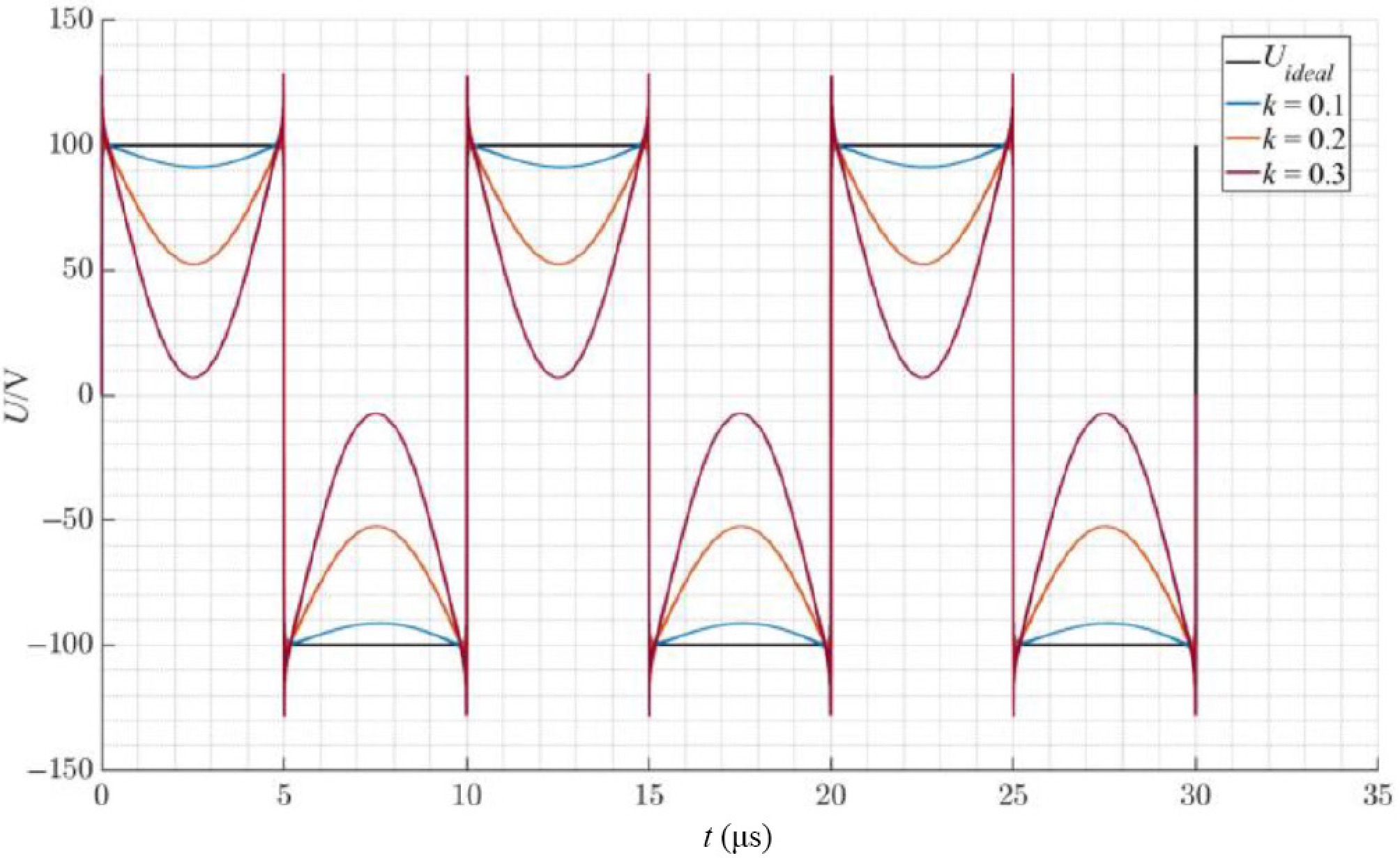
Figure 6.
Output voltage of inverter under different coupling coefficients.
The main reasons are as follows:
(1) If the series resonant inductance Lp is small, the quality factor Q is low, and loss increases.
(2) The influence of the parameter offset is increased with the reflection between stages.
As shown in Fig. 7, taking the inverter voltage with the highest 5th harmonic as the analysis object, when the coupling coefficient k = 0.2, comparing the ideal and non-ideal model, it is found that after increasing the actual component parameter deviation (± 1%), the fundamental amplitude attenuation reaches 21.2% and the phase of each harmonic appears offset. The loss is increased, and the soft switching condition is destroyed by the distortion, which decreases the efficiency, the system stability is degraded, and the device may be damaged.
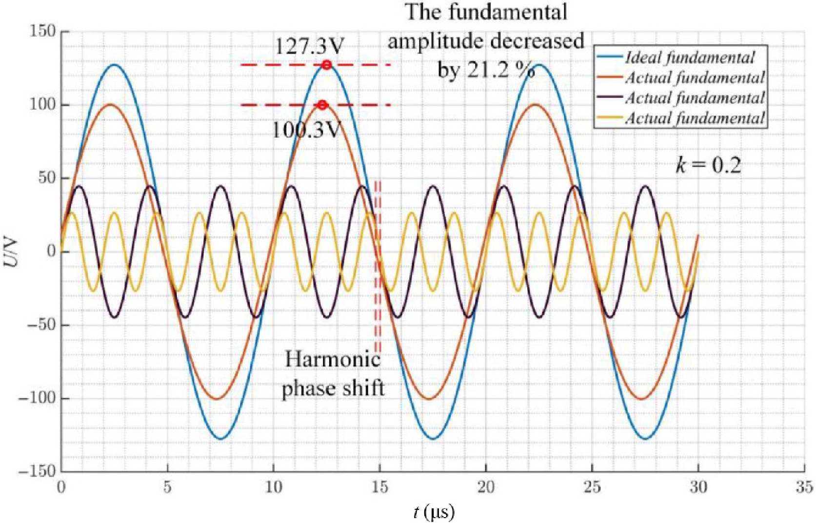
Figure 7.
Analysis of high harmonics of the output voltage of inverter.
Parameter design
-
To address these issues, system efficiency and stability can be enhanced by optimizing topological parameters. If setting Lp = A·L00, fixed k = 0.2, the remaining parameters are configured according to Table 2. By analyzing the output voltage of the inverter under different A (Fig. 8a), it can be found that when A decreases, the voltage distortion will increase, and the total harmonic distortion (THD) will rise.
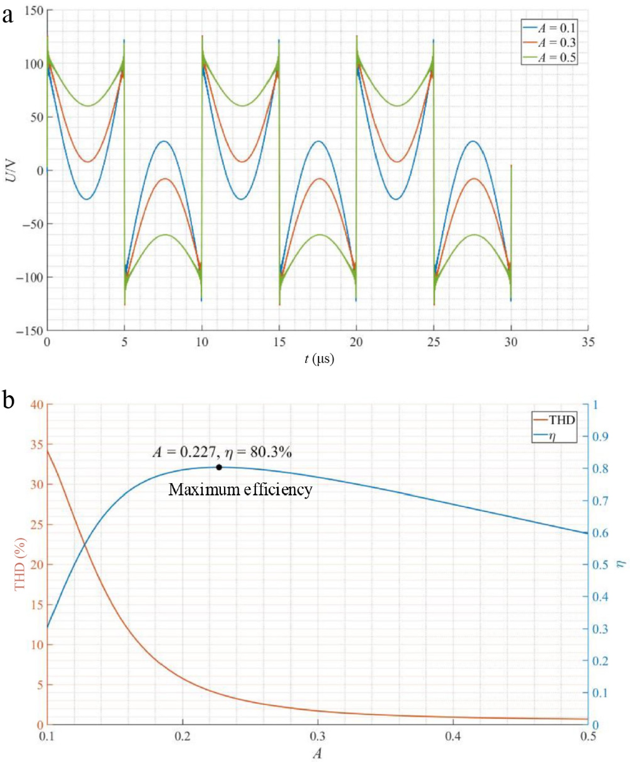
Figure 8.
Effect of parameter A on the system. (a) Output voltage of inverter under different A. (b) THD and η of the system under different A.
Combined with the analysis of Fig. 6, it can be shown that THD is decreased and efficiency is improved by designing A and k.
The coordinated control mechanism of series resonant inductance (Lp) and k is established to optimize the distortion and efficiency. Using Kirchhoff's law and the circuit model in Fig. 5, the equivalent loop equation is shown in Eq. (9).
$ \left[\begin{matrix} a & b & 0 & 0 & 0 & 0\\ b & c & d & 0 & 0 & 0\\ 0 & d & e & f & 0 & 0\\ 0 & 0 & f & g & h & 0\\ 0 & 0 & 0 & h & m & n\\ 0 & 0 & 0 & 0 & n & p \end{matrix} \right]\left[\begin{array}{c} {I}_{p}\\ {I}_{00}\\ {I}_{11}\\ {I}_{12}\\ {I}_{21}\\ {I}_{22} \end{array}\right]=\left[\begin{array}{c} {U}_{ac}\\ 0\\ 0\\ 0\\ 0\\ 0 \end{array}\right] $ (9) Combined with the system resonance conditions shown in Eq. (1), the elements in the matrix are shown in Eq. (10):
$ \begin{cases} a={R}_{com} + {R}_{Lp} + \text{j}\omega {L}_{p} + \dfrac{1}{\text{j}\omega {C}_{p}}\\ b=f=n=-\dfrac{1}{\text{j}\omega {C}_{p}}\\ c={R}_{L00} + \text{j}\omega {L}_{00} + \dfrac{1}{\text{j}\omega {C}_{00}}\\ d=h=-\text{j}\omega {M}_{00\_ 11}\\ e=m={R}_{L11} + \text{j}\omega {L}_{11} + \dfrac{1}{\text{j}\omega {C}_{11}} + \dfrac{1}{\text{j}\omega {C}_{13}}\\ g=p={R}_{eq1} + {R}_{L12} + \text{j}\omega {L}_{12} + \dfrac{1}{\text{j}\omega {C}_{12}} + \dfrac{1}{\text{j}\omega {C}_{13}} \end{cases} $ (10) Equations (11) and (12), respectively, show the efficiency and output power equations. In Eq. (12), Pout is equal to the system total output power.
$ {\eta =\dfrac{{b}^{4}{d}^{2}Req\left({b}^{2}{d}^{2} + {e}^{2}{g}^{2}-2eg{b}^{2} + {b}^{4}\right)}{\left[c{b}^{4} + g{d}^{2}({b}^{2} + {d}^{2})\right]\left[-aceg(2{b}^{2} + {d}^{2}) + {b}^{2}(ac{b}^{2} + ag{d}^{2} + 2eg{b}^{2} + eg{d}^{2}) + ag{d}^{4}\right]}} $ (11) $ {P}_{out}=\dfrac{U_{ac}^{2}{b}^{4}{d}^{2}Req\left({b}^{2}{d}^{2} + {e}^{2}{g}^{2}-2e{b}^{2}g + {b}^{4}\right)}{{\left[-aceg(2{b}^{2} + {d}^{2}) + {b}^{2}(ac{b}^{2} + ag{d}^{2} + 2eg{b}^{2} + eg{d}^{2}) + ag{d}^{4}\right]}^{2}} $ (12) Setting the series resonant inductance as Lp = A∙L00 (A = 0.1, 0.2, ···, 0.5), and Fig. 9 shows the efficiency curve under different parameters. As A increases, the k corresponding to the peak efficiency increases.
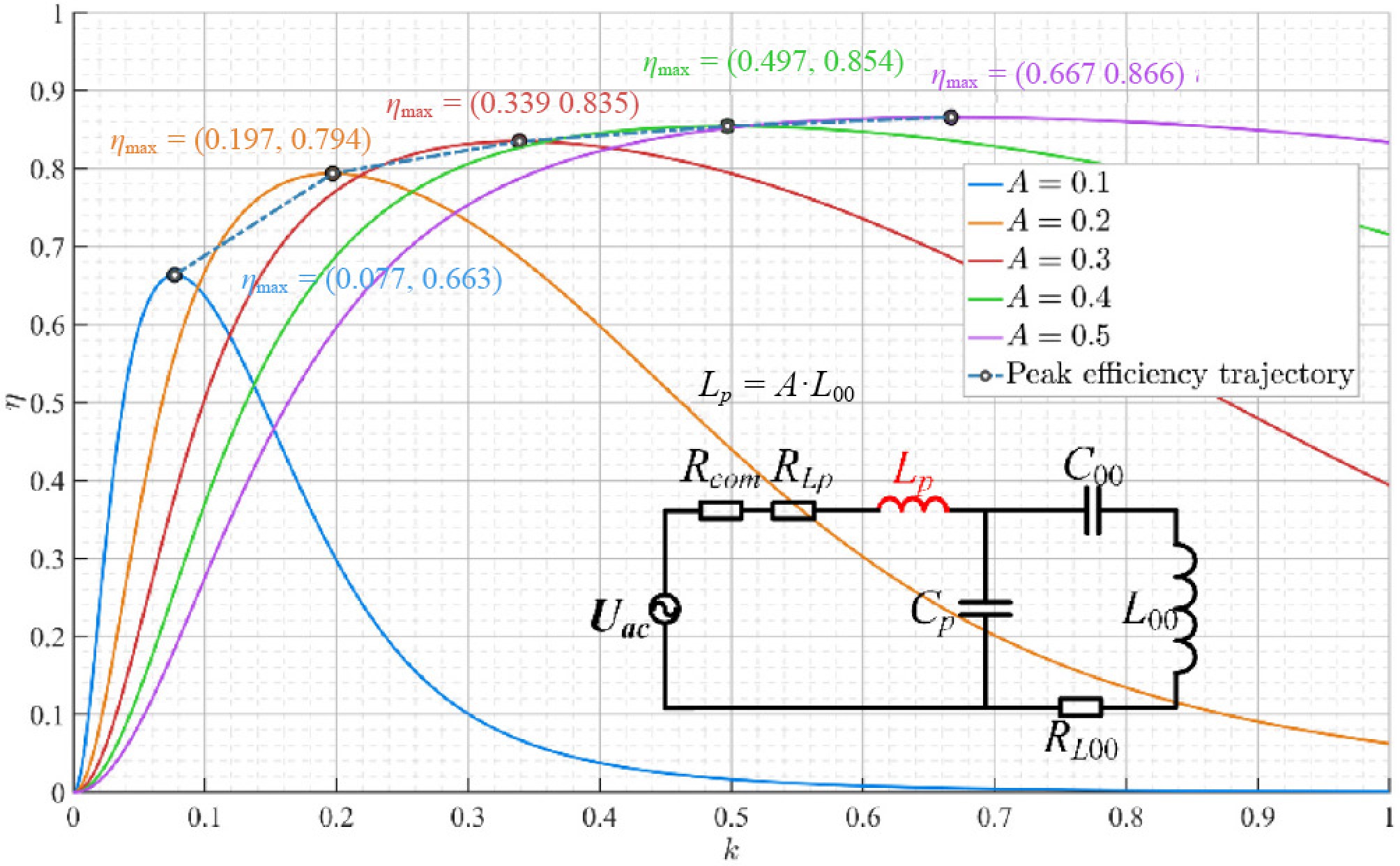
Figure 9.
Effect of coil parameters on system efficiency.
The parameter design procedure for the multi-stage WPT system is illustrated in Fig. 10. This procedure is developed based on theoretical modeling and validated through simulations. By determining an appropriate combination of design parameters in accordance with practical load demands and coil constraints, both the transfer efficiency and output stability of the system can be enhanced.
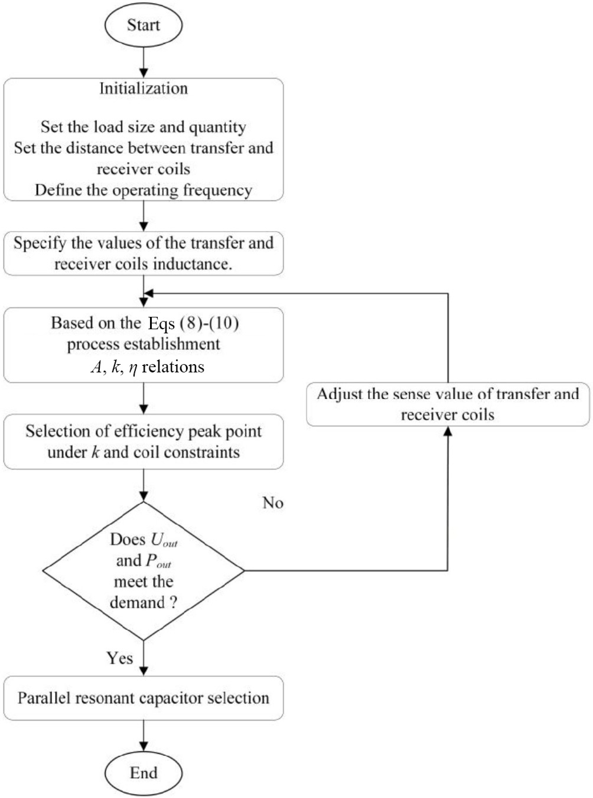
Figure 10.
Flowchart of efficiency optimization.
The detailed design steps are as follows:
(1) Based on practical application requirements, the load size, quantity and power specification are determined; inverter power device on-resistance; the coil-to-coil distance between the transfer and receiver.
(2) The relationship between A, k, and η is established by preset coil inductance and combined with Eqs (8)−(10).
(3) Select the optimal combination of parameters A and k to evaluate whether it meets the system output power and efficiency.
(4) Adjust the transfer and receiver coils, repeat process (3) until the Pout and Uout meet the design requirements, and iteratively optimize the design.
(5) Through the circuit simulation, the voltage waveforms on the capacitor Cp and Ci3 can be obtained, and the peak voltage is used as the core basis for the selection of capacitor withstand voltage.
-
To validate the proposed system model and efficiency optimization method, an experimental platform is established as shown in Fig. 11a. Figure 11b shows the correspondence between the coupling mechanism and the practical coil implementation at the i layer.
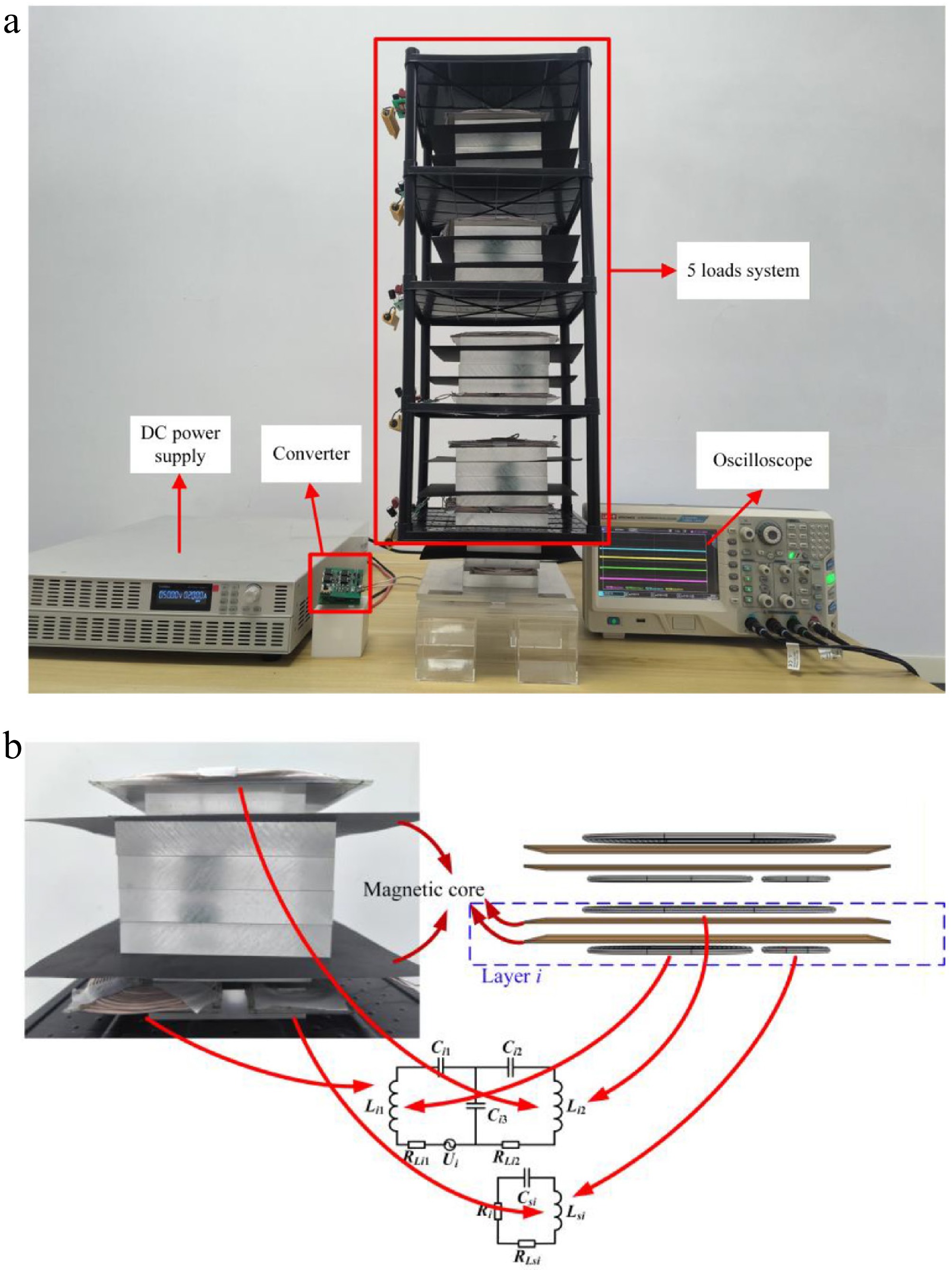
Figure 11.
Experimental platform and coil correspondence of the multi-stage WPT system. (a) Experimental platform. (b) Correspondence of coils in coupling mechanisms.
To enhance the system transmission efficiency, the inductance of the inductance is calculated according to Eq. (11) and Fig. 10, and the capacitance is calculated by Eq. (1). The system contains five stages, and the circuit parameters corresponding to Fig. 2 are shown in Table 3. All stages in the proposed multi-stage WPT system are set to have nearly the same electrical parameters, such as capacitance, inductance, and mutual inductance with neighboring stages. Table 3 shows the system parameters.
Table 3. System parameters.
Parameters Values Parameters Values Udc 50 V Ci1 41.2 nF Lp 29.68 μH Ci2 31.83 nF L00 93.18 μH Ci3 99.7 nF Li1 105 μH Csi1 76.77 nF Li2 87 μH k00_11 0.27 Lsi 33 μH ki2_(i+1)1 0.21 Cp 85.3 nF ki2_si 0.15 C0 40.2 nF Ri 10 Ω The experimental platform is shown in Fig. 11, which is based on the multi-stage WPT system shown in Fig. 2.
Under the condition of the coupling coefficient shown in Table 3, Fig. 12 illustrates the inverter output voltage before and after A optimization. Inverter output voltage distortion decreased by optimizing the A.
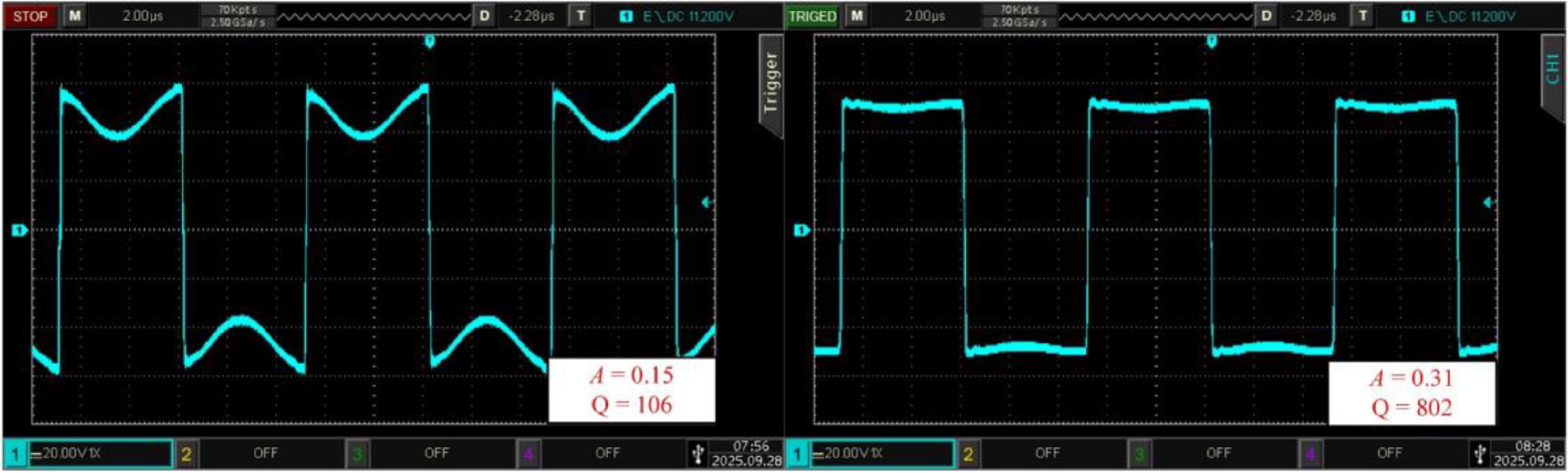
Figure 12.
Effect of A and Q on the output voltage of the inverter.
Figure 13 shows the output voltage of the inverter and the current on inductor Lp.
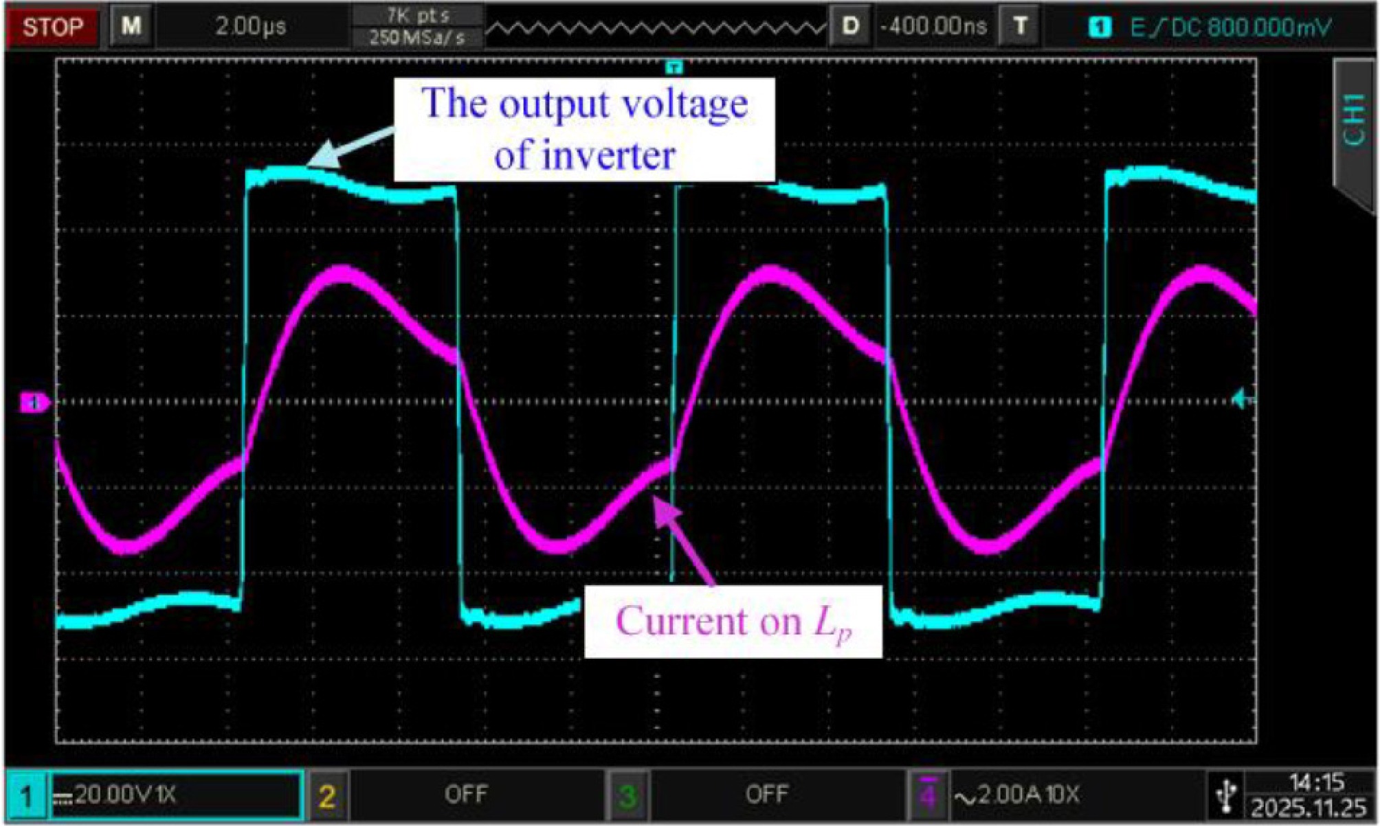
Figure 13.
Input waveform of experimental equipment.
Figure 14 shows the voltage on the five loads in the system. The voltages on each load are UR1 = 14.8 V, UR2 = 12.06 V, UR3 = 10.75 V, UR4 = 9.20 V, UR5 = 11.03 V, and the system transfer efficiency is 84.05%.
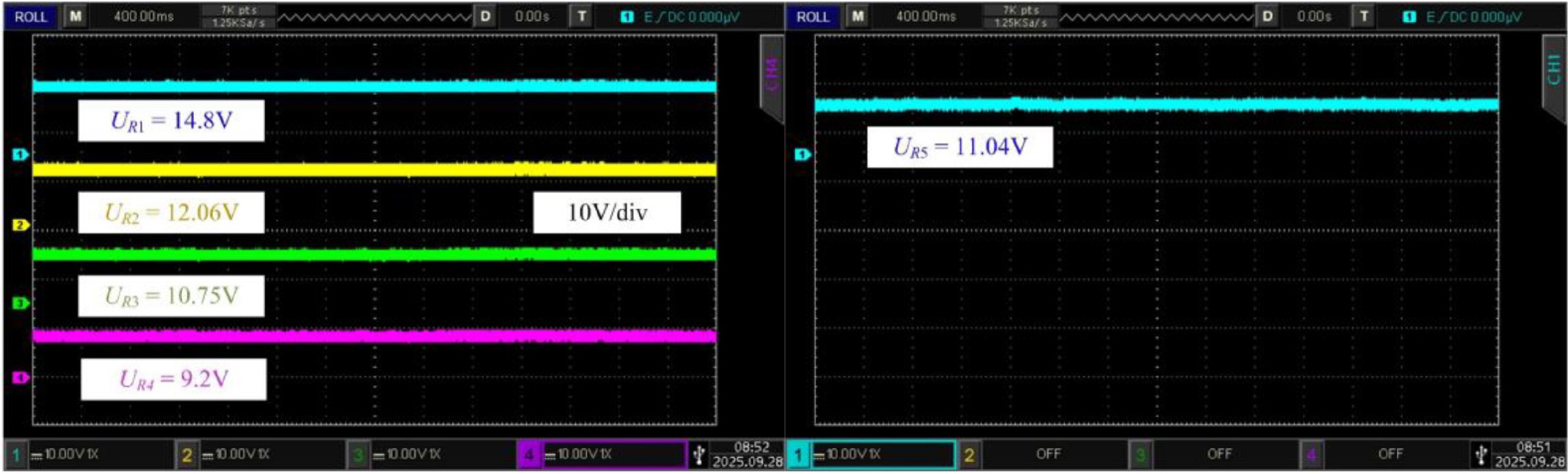
Figure 14.
Output voltage of each load.
In addition, the rectifier input voltage waveforms are shown in Fig 15. The waveforms demonstrate the operating characteristics of the rectifier, further validating the effectiveness of the proposed system model.
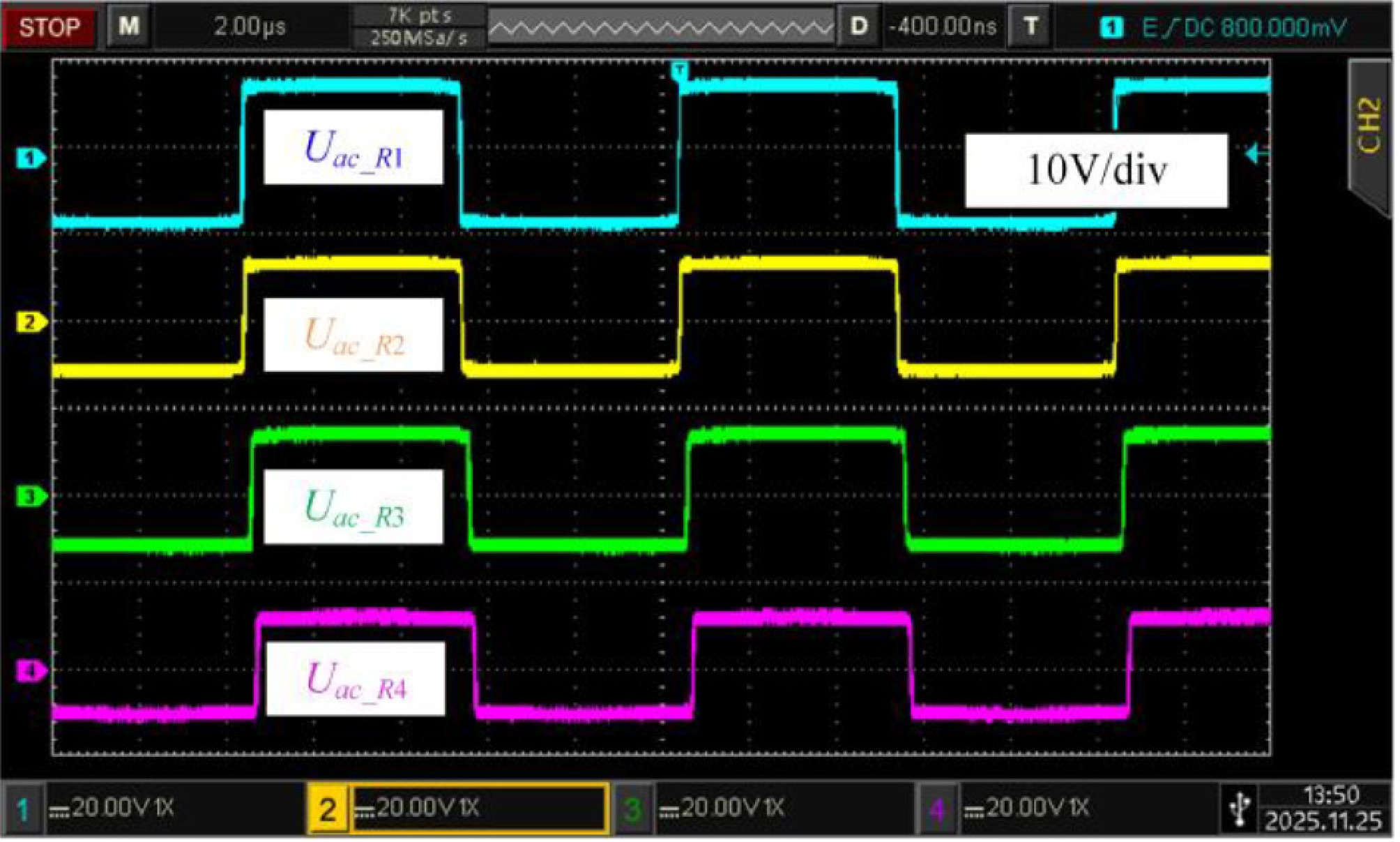
Figure 15.
The rectifier input voltage waveforms.
The load's voltage is shown in Fig. 16, which removes the R3 and R4 when the system is working. The voltages on each load are UR1 = 15.1 V, UR2 = 12.47 V, and UR5 = 11.5 V, and the system transfer efficiency is 83.9%. When a load is removed from the system, the output on other loads is independent, and the system transmission efficiency is stable.
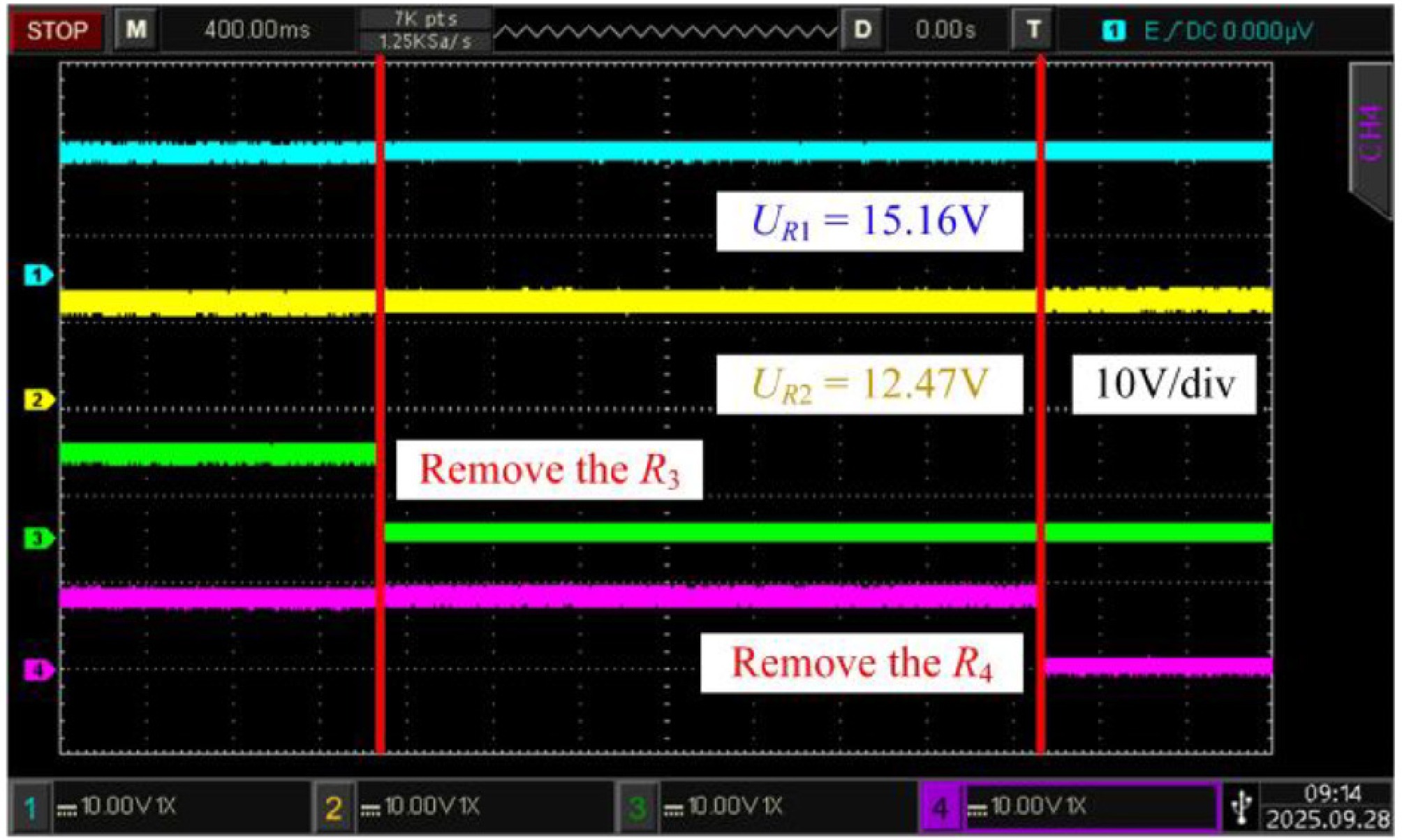
Figure 16.
The influence of load changes on the output voltage of the existing load.
Under the condition of the coupling coefficient shown in Table 3, the efficiency optimization method in Fig. 10 is adopted, and the transfer efficiency curve is shown in Fig. 17.
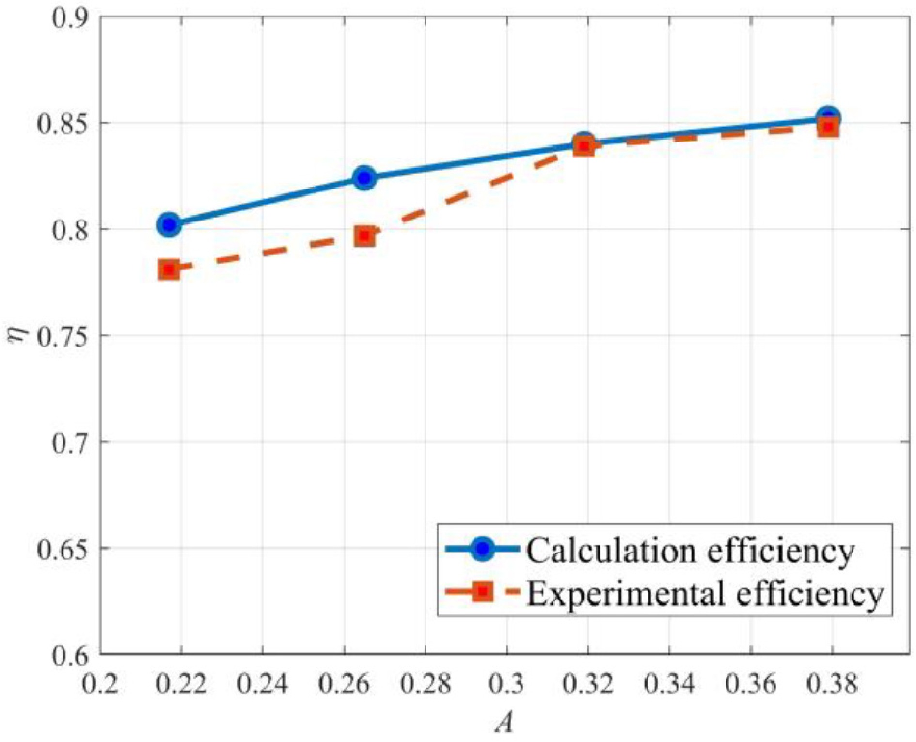
Figure 17.
Calculation efficiency and experimental efficiency under different A.
The discrepancy between the calculated and experimental efficiencies mainly arises from practical non-ideal factors. First, the inductance is obtained from LCR meter measurements, which introduce measurement uncertainties. Second, the resonant capacitors employed in the experiment are subject to manufacturing tolerances, and their actual capacitance values cannot exactly match the designed values. These parameter mismatches lead to a slight detuning of the resonant condition, thereby affecting the measured efficiency. These causes lead to errors, but not more than 5%. Such errors are within the acceptable range and do not affect the main conclusions of this paper.
-
The present study focuses on multi-stage WPT systems used for intelligent pallet. Future work will explore power allocation issues control methods under dynamic load variations. In addition, the proposed multi-stage WPT system and efficiency optimization method has the potential to be extended to other multi-stage power transfer scenarios, such as robotic clusters, unmanned aerial vehicle (UAV) clusters, and electric vehicle clusters.
-
The authors confirm their contributions to the paper as follows: study conception and design: Liang Z, Wu J, Han X, Zhang W, Zhao H; data collection: Liang Z; data analysis and interpretation of results: Liang Z, Wu J; draft manuscript preparation: Liang Z, Wu J. All authors reviewed the results and approved the final version of the manuscript.
-
All data generated or analyzed during this study are included in this published article.
-
This work was supported by the Fundamental Research Program of Shanxi Province (Grant No. 202203021212209), National Natural Science Foundation of China (Grant No. 62176176) and Shanxi Provincial Key Research and Development Project (Grant No. 202102060301012).
-
The authors declare that they have no conflict of interest.
- Copyright: © 2026 by the author(s). Published by Maximum Academic Press, Fayetteville, GA. This article is an open access article distributed under Creative Commons Attribution License (CC BY 4.0), visit https://creativecommons.org/licenses/by/4.0/.
-
About this article
Cite this article
Liang Z, Wu J, Han X, Zhang W, Zhao H. 2026. Research on an efficiency improvement method based on parameter optimization for a multi-stage WPT system in intelligent pallet applications. Wireless Power Transfer 13: e021 doi: 10.48130/wpt-0026-0011 

Research on an efficiency improvement method based on parameter optimization for a multi-stage WPT system in intelligent pallet applications
- Received: 19 November 2025
- Revised: 15 January 2026
- Accepted: 28 February 2026
- Published online: 04 August 2026
Abstract: Due to the application of wireless charging for intelligent pallets, based on the proposed multi-stage wireless power transfer (WPT) system, this paper analyzes the mutual interference between different stages, the parameter conditions of cross-coupling between different stages are obtained, and the sensitivity of output voltages at all stages to mutual inductance and each load are reduced. In addition, the effects of the resonant network parameters on the inverter output voltage and efficiency are investigated, based on which a parameter design strategy is developed to enhance the overall transfer efficiency and system stability is improved. Finally, a five-stage WPT system is designed, and the proposed method is validated.
-
Key words:
- Wireless power transfer /
- Multi-stage system /
- Efficiency optimization