











-
Inductive Power Transfer (IPT), utilizing Faraday's law of electromagnetic induction for power delivery, stands as a prominent research focus within the realm of Wireless Power Transfer (WPT)[1−5]. IPT systems typically require external lumped components to form compensation topologies that achieve resonance, minimizing reactive power between the primary and secondary coils, and thereby enhancing transmission efficiency[5]. However, lumped capacitors generate extremely high electric field strengths within a very small volume, leading to breakdown under large voltages during system operation, which causes system detuning. Similarly, the losses in lumped inductors escalate significantly with operating frequency, particularly in the MHz range, severely degrading system efficiency.
To address this issue, self-resonant (SR) coils replace external lumped compensation components with distributed components, enhancing system stability and efficiency[6−11]. Current SR coils are mainly designed for four low-order compensation topologies (SS, SP, PS, and PP), which can be classified into series and parallel types. SS represents the most widely adopted low-order compensation topology, exhibiting a resonant frequency independent of the coupling coefficient, and enabling constant current output independent of the load. However, the primary current inversely scales with the coupling coefficient, leading to a rapid surge in current when the receiver is absent or distant from the transmitter, potentially damaging the power supply. The higher-order compensation topology LCC-LCC retains the advantages of SS while addressing its safety limitations, offering reduced load sensitivity and greater design flexibility[12,13]. Furthermore, the LCC-LCC topology, featuring a constant-current output[14,15], offers superior adaptability compared with the constant-voltage characteristic of the LCC-S topology, making it more suitable for a wide range of applications, including electric vehicles and other high-power wireless energy transfer systems[16,17]. Although a compact and integrated magnetic coupler based on the LCC-S topology has been reported with cross-coupling elimination[18], a pair of SR coils capable of realizing the double-sided LCC compensation topology has not yet been developed.
This paper proposes an IPT system with double-sided self-resonant LCC coils, where the required compensation elements are integrated with the main coil as distributed elements on a single substrate, eliminating the need for external lumped inductors or capacitors. The proposed system combines the advantages of double-sided LCC compensation and SR coils, which help improve system stability, integration, and operational safety.
To address practical deployment needs, the proposed IPT system targets wireless charging scenarios that require compactness and high integration, ranging from high-power EV wireless charging to low-to-medium power consumer devices (e.g., smartphones), where a load-insensitive constant-current output is beneficial for robust and safe charging. By replacing discrete compensation components with integrated distributed structures, the overall system volume can be reduced, which helps increase the system power density and integration level, while retaining the constant-current characteristic over a wide range of AC loads.
-
This section first presents the structural design methodology for the self-resonant (SR) LCC coil to ensure that the inductive power transfer (IPT) system employing double-sided SR LCC coils effectively exhibits the characteristics of the LCC topology. The proposed structure integrates all compensation components onto a single dielectric substrate, achieving a compact and highly integrated configuration. Subsequently, an equivalent circuit analysis is performed, demonstrating that the resonant frequency remains nearly unaffected by coil misalignment, while the system maintains a stable quasi-constant current output. These results verify that the proposed topology ensures both operational safety and high transmission efficiency under various operating conditions. Finally, an optimized design scheme is proposed to validate the aforementioned AC characteristics and further improve system performance.
SR LCC coil structure
-
To ensure the SR LCC coil exhibits LCC characteristics, the structure is designed in accordance with the IPT system with double-sided SR LCC coils, as shown in Fig. 1[15]. The proposed IPT system with double-sided SR LCC coils integrates all compensation components onto the same dielectric substrate as the primary coil, resulting in five additional mutual-coupling paths. The primary and secondary coils are identical pairs, thus sharing the same component parameters. In this paper, the LCC topology is segmented into three parts: the main coil LA, the parallel capacitor CA, and the series coil LB, denoted by orange, green, and red oval borders, respectively, using the primary side as an example. The implementation approach for the SR LCC coil is to design the above three parts as distributed structures depicted in Fig. 1, and then integrate them onto one dielectric substrate. First, the series coil LB is designed as a conventional planar spiral coil, as indicated by the orange metal conductor in Fig. 1b, corresponding to the series inductor L1 in Fig. 1a. Next, the parallel capacitor CA is designed as two symmetrically distributed gear-shaped metal plates on the upper and lower surfaces of the dielectric substrate, thereby reducing eddy current losses, as illustrated by the two green metal conductors in Fig. 1c, corresponding to the parallel capacitor C1 in Fig. 1a. Finally, the main coil LA is designed as a planar bifilar coil. Unlike traditional designs, the two metal windings are partially intertwined, rather than fully wound together. This partial intertwining allows for flexible control of the capacitance of the equivalent series capacitor CP by adjusting the number of intertwined turns, as shown by the red and yellow metal conductors in Fig. 1d, which correspond to the main inductor LP, and series capacitor CP in Fig. 1a, respectively.
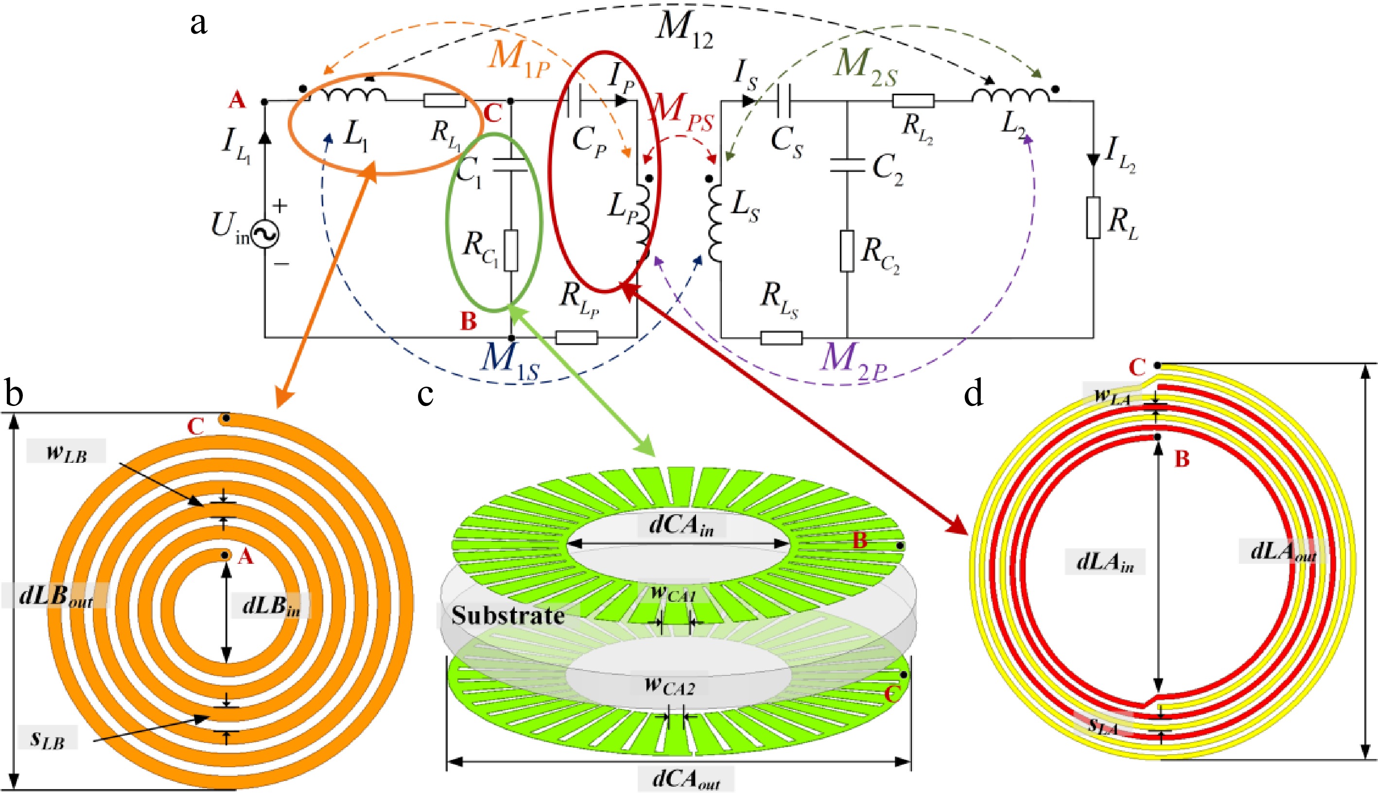
Figure 1.
(a) Equivalent circuit of IPT system with double-sided SR LCC coils. (b) Main coil. (c) Compensation coil. (d) Parallel capacitor.
To clarify the SR coil structure, three points are marked on the primary LCC topology which correspond to the points in the three distributed structures shown in Fig. 1. Point A, representing one terminal of the series coil LB is connected to the power source. Point B denotes the other terminal of the series coil LB, simultaneously serving as one terminal of the main coil LA and one plate of the parallel capacitor CA, and Point C indicates the other terminal of the main coil LA and the other plate of the parallel capacitor CA, also connected to the power source. The SR LCC coil is designed with a series coil, a parallel capacitor, and a main coil arranged from the innermost to the outermost, with identical points in the three distributed structures connected through vias or traces. The overall structure is illustrated in Fig. 2, where the red, yellow, orange, and green parts represent metal conductors, the white part denotes the dielectric substrate, and the blue dots indicate metal vias. Due to the additional mutual inductances arising from the highly integrated structure of the SR LCC coils, an analysis of the IPT system with double-sided self-resonant LCC coils is necessary.
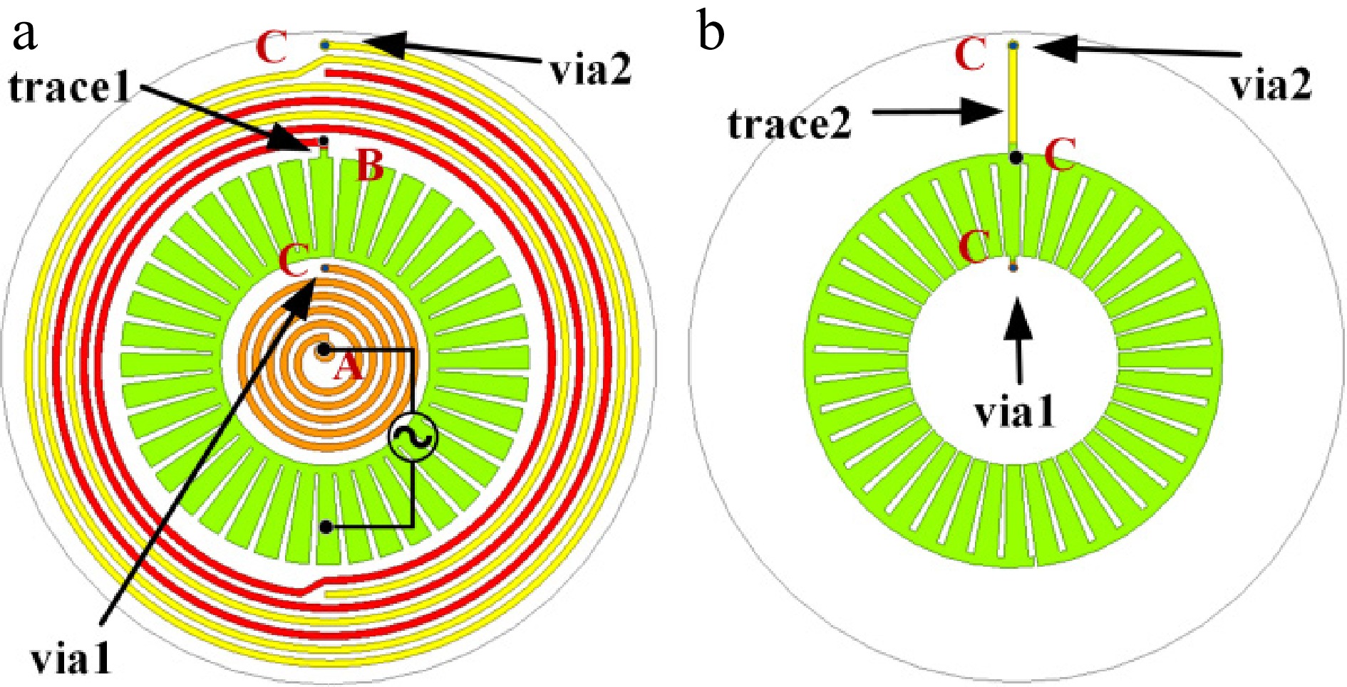
Figure 2.
The SR LCC coil structure. (a) Top view. (b) Bottom view.
Analysis of the IPT system with double-sided self-resonant LCC coils
-
As the size and inductance of the series coil LB are significantly smaller than those of the main coil LA, the minor mutual inductance M12 is negligible. For analytical convenience, the coupling between M1P and M2S in Fig. 1a is decoupled, and the circuit is transformed into an equivalent circuit containing controlled voltage sources as illustrated in Fig. 3, with the relevant parameters expressible as:
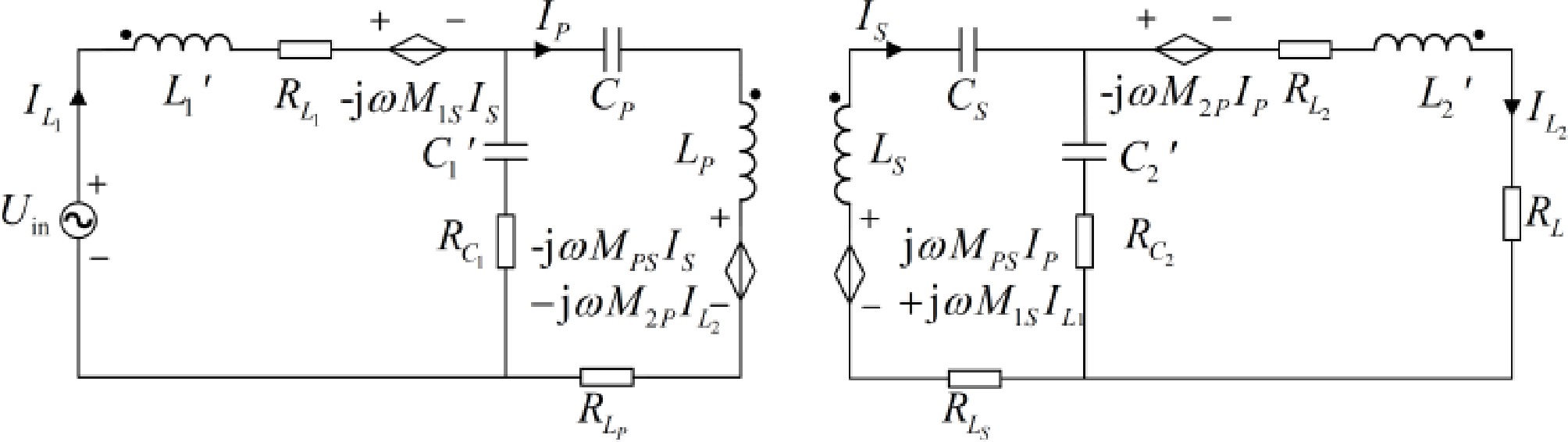
Figure 3.
IPT system with double-sided self-resonant LCC coils after decoupling.
$ \begin{cases} {L}_{1}'={L}_{1}+{M}_{1P} & {L}_{2}'={L}_{2}+{M}_{2S}\\ {L}_{P}'={L}_{P}+{M}_{1P} & {L}_{S}'={L}_{S}+{M}_{2S}\\ {C}_{1}'=\dfrac{1}{\dfrac{1}{{C}_{1}}+{\omega }^{2}{M}_{1P}} & \left\{C_{1}'=\dfrac{1}{\dfrac{1}{{C}_{2}}+{\omega }^{2}{M}_{2S}}\right. \end{cases} $ (1) The KVL equations can be obtained as follows:
$ \begin{cases} {U}_{in}+j\omega {M}_{1S}{I}_{S}=\left(j\omega {L}_{1}'+{R}_{L1}\right){I}_{{{L}_{1}}}+\left(\dfrac{1}{j\omega {C}_{1}'}+{R}_{{{C}_{1}}}\right)\left({I}_{{{L}_{1}}}-{I}_{P}\right)\\ \left(\dfrac{1}{j\omega {C}_{1}'}+{R}_{{{C}_{1}}}\right)\left({I}_{{{L}_{1}}}-{I}_{P}\right)=\left(\dfrac{1}{j\omega {C}_{P}'}+j\omega {L}_{P}'+{R}_{{{L}_{P}}}\right){I}_{P}\\ -j\omega {M}_{PS}{I}_{S}-j\omega {M}_{2P}{I}_{{{L}_{2}}}\\ j\omega {M}_{PS}{I}_{P}+j\omega {M}_{1S}{I}_{{{L}_{1}}}=\left(\dfrac{1}{j\omega {C}_{S}'}+j\omega {L}_{S}'+{R}_{{{L}_{S}}}\right){I}_{S}\\ +\left(\dfrac{1}{j\omega {C}_{2}'}+{R}_{{{C}_{2}}}\right)\left({I}_{S}-{I}_{{{L}_{2}}}\right)\\ \left(\dfrac{1}{j\omega {C}_{2}'}+{R}_{{{C}_{2}}}\right)\left({I}_{S}-{I}_{{{L}_{2}}}\right)+j\omega {M}_{2P}{I}_{P}=\left(j\omega {L}_{2}'+{R}_{{{L}_{2}}}+{R}_{L}\right){I}_{{{L}_{2}}} \end{cases} $ (2) As a pair of SR LCC coils are utilized as the primary and secondary coils, therefore:
$ \begin{cases} {L}_{1}={L}_{2} & \\ {L}_{P}={L}_{S} & \\ {C}_{1}={C}_{2} , \end{cases} \quad \begin{cases} {M}_{1P}={M}_{2S} & \\ {M}_{1S}={M}_{2P} , \end{cases} \quad \begin{cases} {R}_{L1}={R}_{{{L}_{2}}} & \\ {R}_{{{L}_{P}}}={R}_{{{L}_{S}}} & \\ {R}_{{{C}_{1}}}={R}_{{{C}_{2}}} & \end{cases} $ (3) Like conventional double-sided LCC IPT systems, the proposed IPT system satisfies the resonant conditions:
$ \begin{cases} j{\omega }_{0}{L}_{P}+\dfrac{1}{j{\omega }_{0}{C}_{1}}+\dfrac{1}{j{\omega }_{0}{C}_{P}}=0 & \\ j{\omega }_{0}{L}_{S}+\dfrac{1}{j{\omega }_{0}{C}_{2}}+\dfrac{1}{j{\omega }_{0}{C}_{S}}=0 & \end{cases} $ (4) The primary current at resonant frequency can be expressed as:
$ {I}_{S}=\dfrac{j\omega {M}_{1S}{I}_{{{L}_{1}}}+\left[j\omega {M}_{PS}-\dfrac{j\omega {M}_{2P}\left(\dfrac{1}{j\omega C_{2}'}+{R}_{{{C}_{2}}}\right)}{{Z}_{L}}\right]{I}_{P}}{\left({R}_{{{L}_{S}}}+{R}_{{{C}_{2}}}\right)+\dfrac{{\left(\dfrac{1}{j\omega C_{2}'}+{R}_{{{C}_{2}}}\right)}^{2}}{{Z}_{L}}}$ (5) $ {I}_{{{L}_{2}}}=\dfrac{j\omega {M}_{1S}{I}_{P}+\left(\dfrac{1}{j\omega C_{1}'}+{R}_{{{C}_{1}}}\right){I}_{S}}{{Z}_{L}} $ (6) ${I}_{p}=\dfrac{j\omega {M}_{1s}{I}_{{{L}_{1}}}+\left[j\omega {M}_{pS}-\dfrac{j\omega {M}_{2p}\left(\dfrac{1}{j\omega C_{2}'}+{R}_{{{C}_{2}}}\right)}{{Z}_{L}}\right]{I}_{p}}{\left({R}_{{{L}_{S}}}+{R}_{{{C}_{2}}}\right)+\dfrac{{\left(\dfrac{1}{j\omega C_{2}'}+{R}_{{{C}_{2}}}\right)}^{2}}{{Z}_{L}}} $ (7) As the negligible impact of losses on the resonant frequency, the resonant frequency derived from Eq. (2) can be expressed as:
$ {\omega }_{0}=\sqrt{\dfrac{1}{{C}_{1}}\left(\dfrac{1+2\dfrac{{K}_{1S}}{{K}_{PS}}\sqrt{\dfrac{{L}_{1}}{{L}_{P}}}}{{L}_{1}\left(1-2\dfrac{{K}_{1S}}{{K}_{PS}}{K}_{1P}\right)}\right)} $ (8) The resonant frequency ω0 is determined by the inductances L1 and LP, the capacitance C1, the primary coupling coefficient KPS, as well as the cross-coupling factors K1S and the intra-side coupling coefficient K1P. Since the series coil LB of the SR LCC network is integrated on the same dielectric substrate together with the main coil LA and the parallel capacitor CA, their relative positions remain fixed during power transfer. Consequently, K1P can be regarded as constant. In summary, it is only necessary to verify whether K1S remains approximately constant under vertical and horizontal coil displacements in order to determine whether the resonant frequency ω0 is independent of the coupling coefficients during transmission.
All coils proposed in this study are designed to operate at 13.56 MHz. Accordingly, the real part of the primary input impedance at resonance, Re[Zin], can be simplified by retaining only the dominant terms, yielding the following expression:
$ \text{Re}[{Z}_{\text{in}}]=\dfrac{{R}_{LA}+{R}_{CA}}{C_{1}^{'2}\omega _{0}^{2}Z_{4}^{2}}+\dfrac{M_{PS}^{2}\left({R}_{LA}+{R}_{CA}\right)}{C_{1}^{'2}{Z}_{5}Z_{4}^{2}}+\dfrac{M_{PS}^{2}\left({R}_{L}+{R}_{LA}\right)}{C_{1}^{'4}\omega _{0}^{2}{Z}_{6}{Z}_{5}Z_{4}^{2}} $ (9) where,
$\begin{split} {Z}_{4}=\;&{R}_{LA}+{R}_{CA}+\dfrac{M_{1S}^{2}\left({R}_{L}+{R}_{LA}\right)\omega _{0}^{2}}{{Z}_{6}}-\dfrac{{M}_{1S}{M}_{PS}\left({R}_{L}+{R}_{LA}\right)\left(\dfrac{1}{{\omega }_{0}C_{1}'}-{\omega }_{0}L_{1}'\right)}{C_{1}^{'3}{\omega }_{0}Z_{6}^{2}{Z}_{5}}\\ &+\dfrac{\left(\dfrac{2L_{1}'M_{1S}^{2}\left({R}_{L}+{R}_{LA}\right){\omega }_{0}}{C_{1}^{'2}Z_{6}^{2}}-\dfrac{2M_{1S}^{2}\left({R}_{L}+{R}_{LA}\right)}{C_{1}^{'3}{\omega }_{0}Z_{6}^{2}{Z}_{5}}-\dfrac{{M}_{1S}{M}_{PS}\left({R}_{L}+{R}_{LA}\right)}{C_{1}'{Z}_{6}}\right)\left(\dfrac{1}{{\omega }_{0}C_{1}'}-{\omega }_{0}L_{1}'\right)}{C_{1}^{'2}\omega _{0}^{2}{Z}_{6}{Z}_{5}}\\ &+\dfrac{{M}_{PS}}{{Z}_{5}}{\omega }_{0}\left({R}_{L}+{R}_{LA}+\dfrac{{R}_{L}+{R}_{LA}}{{C}_{1}^{'2}{{{\omega }_{0}}}^{2}{Z}_{6}}\right)\left({M}_{PS}{\omega }_{0}+\dfrac{{M}_{1S}\left(\dfrac{1}{{{{\omega }_{0}}C}_{1}'}-{{{\omega }_{0}}L}_{1}'\right)}{{C}_{1}'{Z}_{6}}\right)\\ &+\left(\dfrac{{R}_{L}+{R}_{LA}}{C_{1}'\omega _{0}^{2}{Z}_{6}}+{R}_{L}+{R}_{LA}\right)\left[\dfrac{{M}_{1S}\left(\dfrac{1}{{\omega }_{0}C_{1}'}-{\omega }_{0}L_{1}'\right)\left(\dfrac{{M}_{1S}\left(\dfrac{1}{\omega }_{0}C_1'-{\omega }_{0}L_{1}'\right)}{C_1'{Z}_{6}}+{M}_{PS}{\omega }_{0}\right)}{C_{1}'{Z}_{6}{Z}_{5}}-\dfrac{M_{1S}^{2}{\left({R}_{L}+{R}_{LA}\right)}^{2}}{C_{1}^{'2}Z_{6}^{2}{Z}_{5}}\right]\end{split} $ (10) $ {Z}_{5}=\dfrac{{\left(\dfrac{1}{{\omega }_{0}{C}_{1}}-{\omega }_{0}L_{1}'\right)}^{2}}{\omega _{0}^{4}C_{1}^{'4}Z_{6}^{2}}+{\left({R}_{L}+{R}_{LA}+\dfrac{{R}_{L}+{R}_{LA}}{\omega _{0}^{2}C_{1}^{'2}{Z}_{6}}\right)}^{2} $ (11) ${Z}_{6}={\left({R}_{L}+{R}_{LA}\right)}^{2}+{\left({\omega }_{0}L_{1}'-\dfrac{1}{{\omega }_{0}C_{1}'}\right)}^{2}$ (12) The primary current IL1 at resonant frequency can be expressed as:
$ {I}_{{{L}_{1}}}=\dfrac{{U}_{\text{in}}}{\text{Re}[{Z}_{\text{in}}]} $ (13) From Eq. (10) it follows that Z4 is proportional to MPS2. Therefore, for the real part of the primary input impedance Re[Zin], the numerator scales with MPS2 while the denominator scales with MPS4, consequently, Re[Zin] is inversely proportional to MPS2. Further, according to Eq. (13), the primary input current IL1 is proportional to MPS2. Hence, when the secondary coil moves away from the primary coil—or under open-circuit (no-load) conditions—the primary input current decreases accordingly and will not harm the front-end power source. This behavior thus mitigates the safety issue associated with S–S compensated IPT systems.
Substituting Eq. (13) into Eq. (7) and simplifying yields the following expression for the primary main-coil current IP :
$ {I}_{P}=-j{\omega }_{0}{U}_{\text{in}}{C}_{1}' $ (14) Substituting Eqs (13), (14), and (5) into Eq. (6) and simplifying, the output current IL2 is obtained as:
$ \begin{split}I_{L_2}=\;&j\Bigg[\dfrac{{M}_{1S}{U}_{\text{in}}{\omega }_{0}}{{Z}_{6}}-\dfrac{C_{1}'L_{1}'{M}_{1S}{U}_{\text{in}}\omega _{0}^{3}}{{Z}_{6}}-\dfrac{{M}_{1S}{U}_{\text{in}}}{C_{1}^{'6}\omega _{0}^{5}Z_{6}^{3}{Z}_{5}}+\dfrac{3L_{1}'{M}_{1S}{U}_{\text{in}}}{C_{1}^{'5}\omega _{0}^{3}Z_{6}^{3}{Z}_{5}}\\ &-\dfrac{{M}_{1S}{\left({R}_{L}+{R}_{LA}\right)}^{2}{U}_{\text{in}}}{C_{1}^{'4}\omega _{0}^{3}Z_{6}^{3}{Z}_{5}}-\dfrac{3{{{L}_{1}}}^{2}{M}_{1S}{U}_{\text{in}}}{C_{1}^{'4}{\omega }_{0}Z_{6}^{3}{Z}_{5}}+\dfrac{L_{1}'{M}_{1S}{\left({R}_{L}+{R}_{LA}\right)}^{2}{U}_{\text{in}}}{C_{1}^{'3}{\omega }_{0}Z_{6}^{3}{Z}_{5}}\\ &+\dfrac{L_{1}^{'3}{M}_{1S}{U}_{\text{in}}{\omega }_{0}}{C_{1}^{'3}Z_{6}^{3}{Z}_{5}}-\dfrac{{M}_{PS}{U}_{\text{in}}}{C_{1}^{'4}\omega _{0}^{3}Z_{6}^{3}{Z}_{5}}+\dfrac{2L_{1}'{M}_{PS}{U}_{\text{in}}}{C_{1}^{'3}{\omega }_{0}Z_{6}^{3}{Z}_{5}}-\dfrac{{M}_{PS}{\left({R}_{L}+{R}_{LA}\right)}^{2}{U}_{\text{in}}}{C_{1}^{'2}{\omega }_{0}Z_{6}^{3}{Z}_{5}}\\ &-\dfrac{L_{1}^{'2}{M}_{PS}{U}_{\text{in}}{\omega }_{0}}{C_{1}^{'2}Z_{6}^{3}{Z}_{5}}-\dfrac{{M}_{PS}\left({R}_{L}+{R}_{LA}\right)\left({R}_{LA}+{R}_{CA}\right){U}_{\text{in}}{\omega }_{0}}{Z_{6}^{3}{Z}_{5}}\Bigg]\\[-1pt]\end{split} $ (15) When the AC load RL is much greater than the intrinsic loss of the SR LCC coil, the output current IL2 becomes independent of RL, and can be expressed as:
$ {I}_{{{L}_{2}}}\approx -C_{1}^{'2}{M}_{PS}{U}_{\text{in}}{{{\omega }_{0}}}^{3} $ (16) Therefore, the SR coil with the proposed double-sided LCC compensation topology exhibits a nearly constant-current output that is independent of the AC load. Moreover, the output current is directly proportional to the primary mutual coupling coefficient MPS.
Furthermore, the corresponding expressions for the output power and system efficiency can be derived. Among them, the output power is proportional to the primary mutual coupling coefficient MPS.
${P}_{out}={R}_{L}{{{I}_{{{L}_{2}}}}}^{2} $ (17) $ \eta =\dfrac{{R}_{L}I_{{L}_{2}}^{2}}{{U}_{\text{in}}{I}_{{{L}_{1}}}}$ (18) Therefore, it can be concluded that the SR coil with the double-sided LCC compensation topology ensures safe operation of the front-end power source even when the secondary coil is significantly misaligned or under no-load conditions, while maintaining a quasi-constant current output that is largely independent of the AC load.
Dimension design of coils for a double-sided self-resonant coil IPT system
-
The SR coil with double-sided LCC compensation characteristics is designed to operate within a high-efficiency transmission range corresponding to load resistances of 10–50 Ω. To ensure that the proposed integrated self-resonant double-sided LCC coils operate at 13.56 MHz, a circuit-field co-design methodology was adopted, combining circuit-level synthesis with FEM-based electromagnetic (EM) simulations. First, the practical design targets were specified, including the operating frequency, the intended transfer-distance range (20–50 mm), and a power level around 10 W. A size constraint was imposed by setting the outer diameter of the main coil at 100 mm. Based on these targets, an equivalent double-sided LCC circuit model was established and optimized to obtain a target set of compensation parameters. Next, the filament current method was employed as a semi-analytical tool to determine an initial geometry for the main coil (e.g., inner/outer diameters, number of turns, winding space, and width) that meets the inductance and coupling-related requirements. It should be noted that the key parameters in this work are not obtained only through FEM simulations. The resonant frequency can be derived from the equivalent circuit model, and the inductance and coupling coefficients can be initially estimated by analytical methods, such as the filament method. However, because the proposed SR LCC coil integrates distributed inductive and capacitive elements on a single substrate, the parasitic coupling effects are more complicated than those in conventional lumped-compensation circuits. Therefore, FEM simulations are used to refine the structural dimensions and accurately extract the effective parameters. In this work, the design methodology combines theoretical calculation, FEM-based optimization, and experimental validation.
Subsequently, FEM simulations were performed to refine the integrated main coil structure. In this step, we aim to optimize the coil quality factor (Q) as well as extract the effective parameters of the distributed implementation, particularly the main inductance LP and the series capacitance CP associated with the coil structure. The extracted LP and CP were then fed back into the circuit model to further optimize the remaining compensation elements, namely, the series inductor L1 and the parallel capacitor C1. The optimized targets of L1 and C1 were subsequently realized through FEM-based EM design, where their dimensional parameters were tuned until the EM-extracted behaviors match the circuit-level targets. Finally, full-structure FEM simulations of the complete SR double-sided LCC coil set were conducted to verify that the overall system resonates at 13.56 MHz, and supports efficient magnetic-field-based power transfer under the designed operating condition. The final equivalent-circuit parameters are summarized in Table 1, the final coil dimensional parameters are listed in Table 2, and the optimized AC loss resistances and corresponding quality factors of the three integrated structural components at 13.56 MHz are listed in Table 3.
Table 1. Equivalent circuit parameters of double-sided LCC SR coil IPT system.
Parameter Simulated value Measured value Main inductor LP, LS 4.52 μH 4.46 μH Series inductor L1, L2 0.765 μH 0.74 μH Parallel capacitor C1, C2 155.42 pF 159.6 pF Series capacitor CP, CS 37.9 pF 40.4 pF Primary coupling coefficient KPS 0.186 N/A Intra-side coupling coefficient K1P, K2S −0.08 N/A Cross-coupling coefficient K1S, K2P −0.036 N/A Minor coupling coefficient K12 0.018 N/A Table 2. Dimensional parameters of coils.
Dimensional parameter Description Value dLAin Inner diameter of LA 71 mm dLAout Outer diameter of LA 100 mm NLA Turn numbers of LA 5 wLA Winding width of LA 0.83 mm sLA Winding space of LA 1.52 mm dCAin Inner diameter of CA 33 mm dCAout Outer diameter of CA 67 mm wCA1 Inner width of each tooth of CA 2.22 mm wCA2 Outer width of each tooth of CA 3.8 mm dLBin Inner diameter of LB 6.525 mm dLBout Outer diameter of LB 28 mm NLB Turn numbers of LB 7 wLB Winding width of LB 0.85 mm sLB Winding space of LB 1.45 mm Table 3. Optimized Q and associated losses of double-sided LCC SR coil IPT system.
Structural components Loss (Ω) Q LCC SR main coil LA 1.8 214 Compensation coil LB 0.4 163 Parallel capacitor CA 0.2 377.6 The magnetic-field distribution of the primary and secondary coils was obtained from FEM simulations, as shown in Fig. 4a. The double-sided SR LCC coils are placed with the designed transfer distance of 35 mm, and the magnetic flux is mainly concentrated in the space between the two coils, indicating effective magnetic coupling. Figure 4b presents the electric-field distribution on the YOZ plane. The electric field is primarily localized around the coil structures and shows no noticeable outward radiation, confirming that power transfer in the proposed system is dominated by magnetic coupling rather than electric-field radiation.
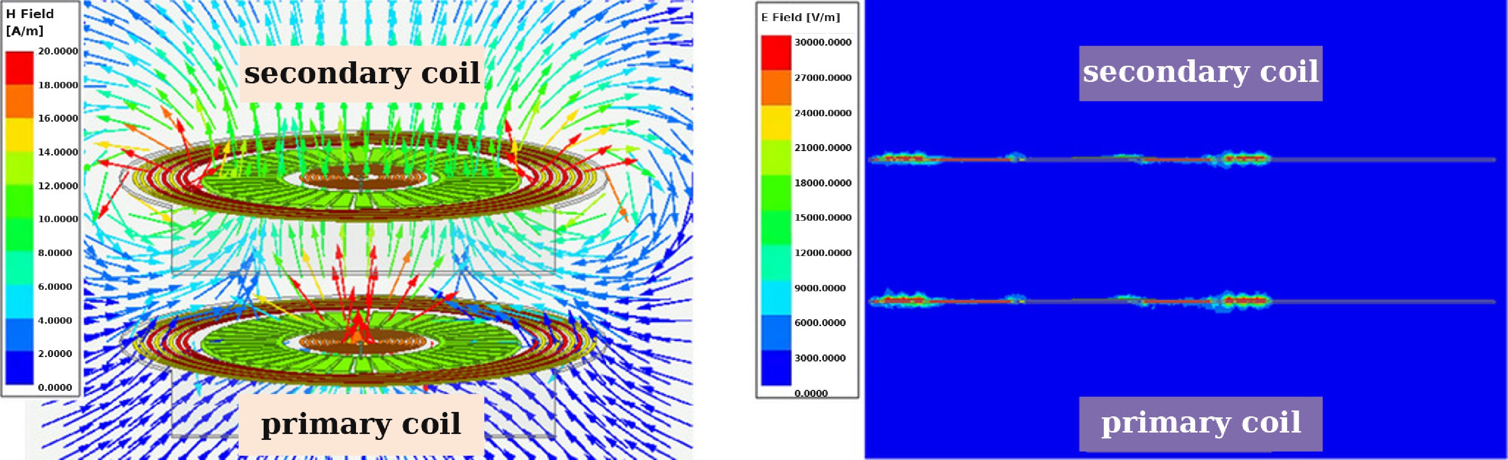
Figure 4.
Field distribution of the coils. (a) Magnetic field distribution. (b) Electric field distribution.
According to Eq. (8), the resonant frequency ω0 is independent of the AC load RL. However, it depends on the ratio of the coupling coefficients K1S/KPS and the intra-side coupling coefficient K1P. For the SR LCC coil, the series coil LB, the primary main coil LA, and the parallel capacitor CA are integrated on the same dielectric substrate, ensuring that their relative positions remain fixed during power transfer. Therefore, K1P can be regarded as a constant.
To determine whether the resonant frequency remains nearly constant under coupling variations during transmission, it is necessary to analyze whether |K1S/KPS| remains approximately constant when the primary and secondary coils experience variations in both vertical and lateral displacement. Since the coupling coefficients depend solely on the coil positioning, they can be accurately calculated using the filament method[19].
By substituting the coil dimensional parameters listed in Table 2 into the above equations, the variation of |K1S/KPS| with respect to different vertical (dv) and lateral (dl) displacements can be obtained, as illustrated in Fig. 5a. When the vertical distance between the primary and secondary coils varies from 20 to 50 mm while the lateral displacement remains dl = 0, |K1S/KPS| stays nearly constant. Similarly, when the lateral displacement varies from 0 to 25 mm with a fixed vertical distance of 35 mm, |K1S/KPS| also remains approximately constant. Therefore, when the coils are designed according to the dimensional parameters, the resonant frequency can be considered nearly invariant under misalignment-induced coupling variations, demonstrating excellent alignment tolerance.
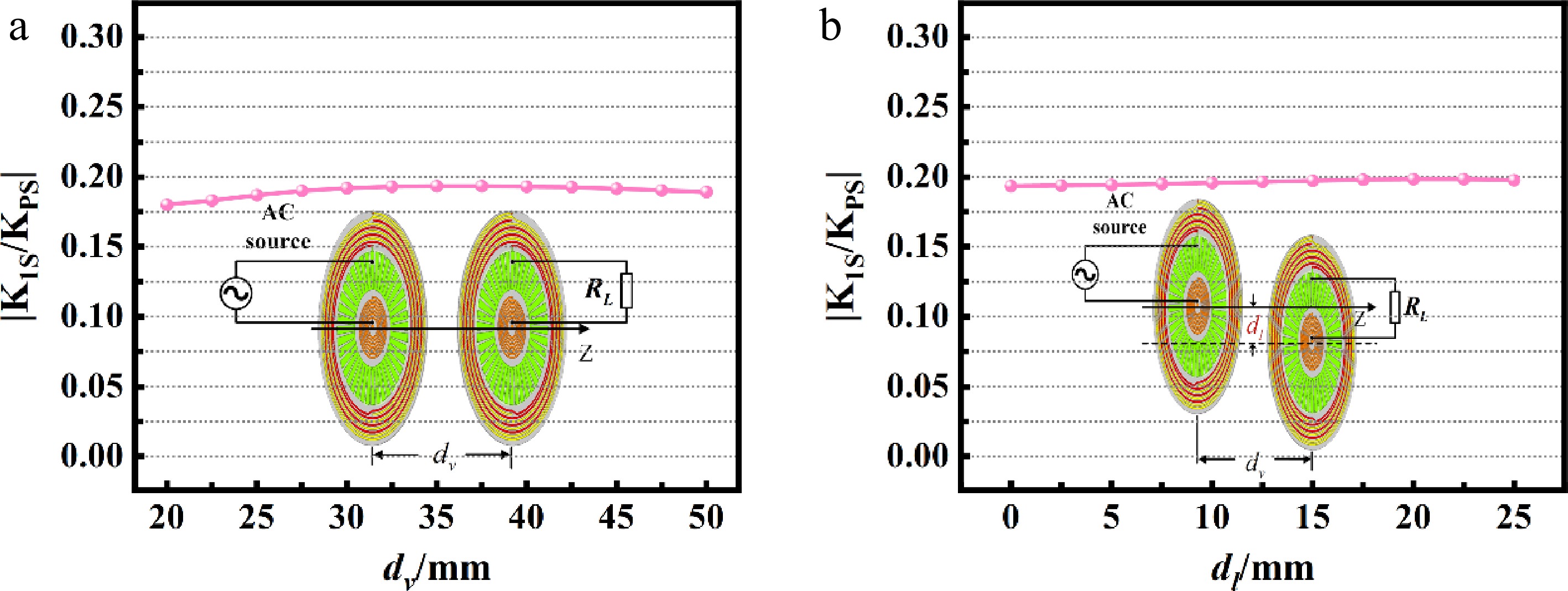
Figure 5.
The variation curve of K1S/KPS. (a) $ {d}_{v} $ changes. (b) $ {d}_{l} $ changes at a fixed $ {d}_{v} $ of 35 mm.
Subsequently, based on the coil dimensional parameters listed in Table 2, a controlled-variable method was employed to investigate the influence of individual coil dimensions on |K1S/KPS| under varying dv and dl. This analysis aims to determine the conditions under which the resonant frequency remains independent of the coupling coefficients. Since the outer diameter of the main coil LA was fixed at 100 mm, the dimensional relationships among the SR LCC coil components were defined as follows:
$m=\dfrac{dL{B}_{in}}{dL{B}_{out}},\;\;n=\dfrac{dL{A}_{in}}{dL{A}_{out}},\;\;p=\dfrac{dL{B}_{out}}{dL{A}_{out}} $ (19) Meanwhile, because the outer diameters of the main coil LA and the series coil LB must be larger than their inner diameters, and sufficient spacing must be reserved between LA and LB for the placement of the parallel capacitor CA, the parameter constraints in Eq. (19) were defined as:
$ 0.2\leq m\leq 0.8{,}\;\;0.3\leq n\leq 0.8{,}\;\;0.2\leq p\leq 0.6 $ (20) The influence of the parameters in Eq. (19) on |K1S/KPS| under different coil displacements is illustrated in Figs 6 and 7. When dl = 0 and dv varies from 20 to 50 mm, as well as when dv = 35 mm and dl varies from 0 to 25 mm, the variation trends of |K1S/KPS| are analyzed for different parameter values. As shown, |K1S/KPS| remains approximately constant when the parameters m and p vary. However, the parameter n plays a key role in affecting |K1S/KPS|. From Figs 6b and 7b, it can be observed that when n is set in the range of 0.5–0.7, |K1S/KPS| remains nearly constant.
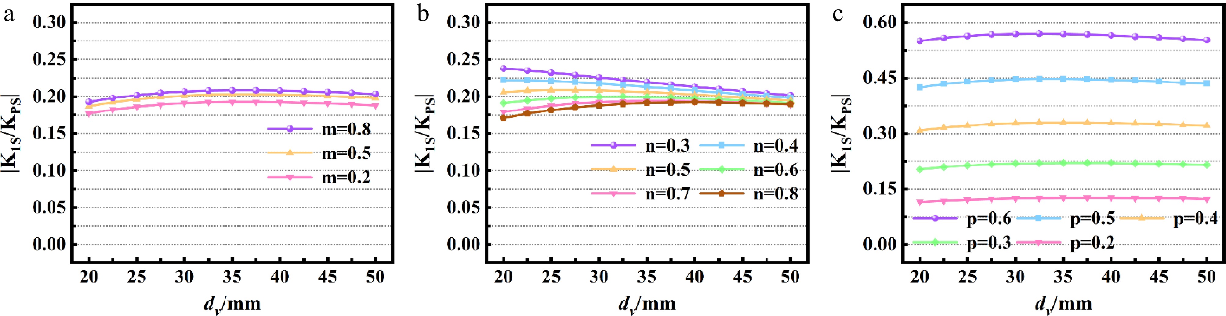
Figure 6.
The variation curve of K1S/KPS with changes in dv when (a) dLBin changes; (b) dLCin changes; and (c) dLBout changes.
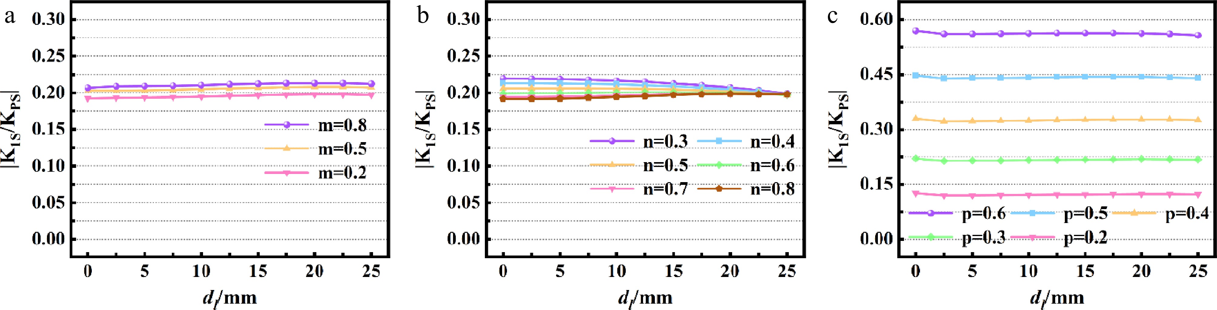
Figure 7.
The variation curve of K1S/KPS with changes in dl at a fixed dv of 35 mm when (a) dLBin changes; (b) dLAin changes; and (c) dLBout changes.
In this section, n is set to 0.71 to satisfy LP specified in Table 1, while maintaining high transmission efficiency. As shown in Fig. 5, |K1S/KPS| still remains approximately constant, verifying that the designed SR LCC coil maintains the resonant frequency independent of the coupling coefficient.
-
In this section, an AC-AC experimental verification was carried out to confirm the resonant frequency is insensitive to coupling variations, and to validate the approximately constant output current under varying AC loads. Furthermore, the transmission characteristics achieving high efficiency across a wide range of AC loads were investigated.
Prototype fabrication and experimental validation
-
The fabricated coils, designed according to the dimensional parameters specified in Table 2, are shown in Fig. 8.
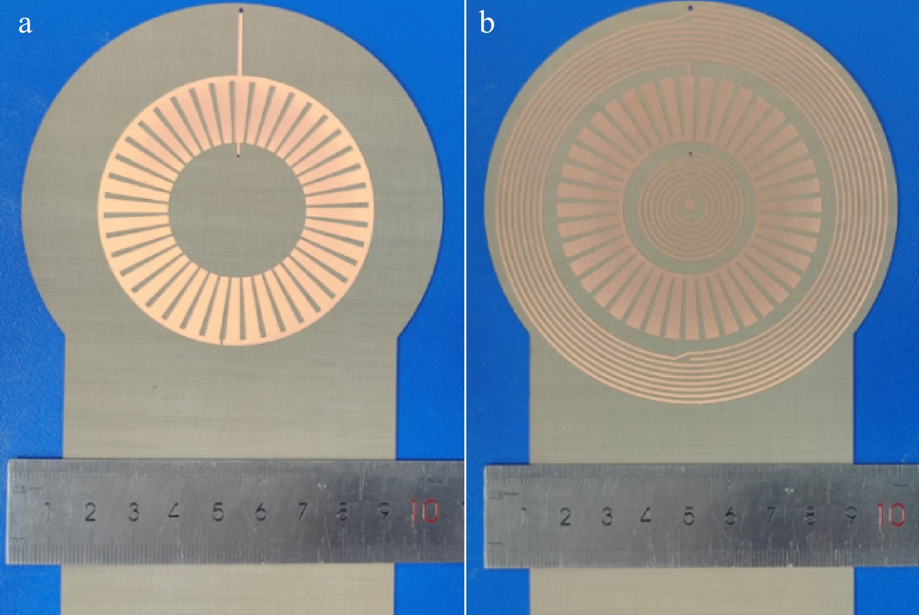
Figure 8.
Fabricated coils. (a) Top view of the LCC SR coil. (b) Bottom view of the LCC SR coil.
To validate the resonance behavior of the proposed SR coil set, impedance measurement was conducted using a Keysight N5277A vector network analyzer (VNA). The measurement frequency range was set to 10–15 MHz. The transmitter and receiver SR coils were aligned and placed with an air gap of approximately 35 mm, which is the nominal operating distance adopted in the coil design, and the coil terminals were connected to the two ports of the VNA. The measured Smith chart shown in Fig. 9 indicates that the proposed SR coils set resonates around 13.56 MHz, satisfying the design requirement and confirming the desired self-resonant behavior under the nominal coupling condition.
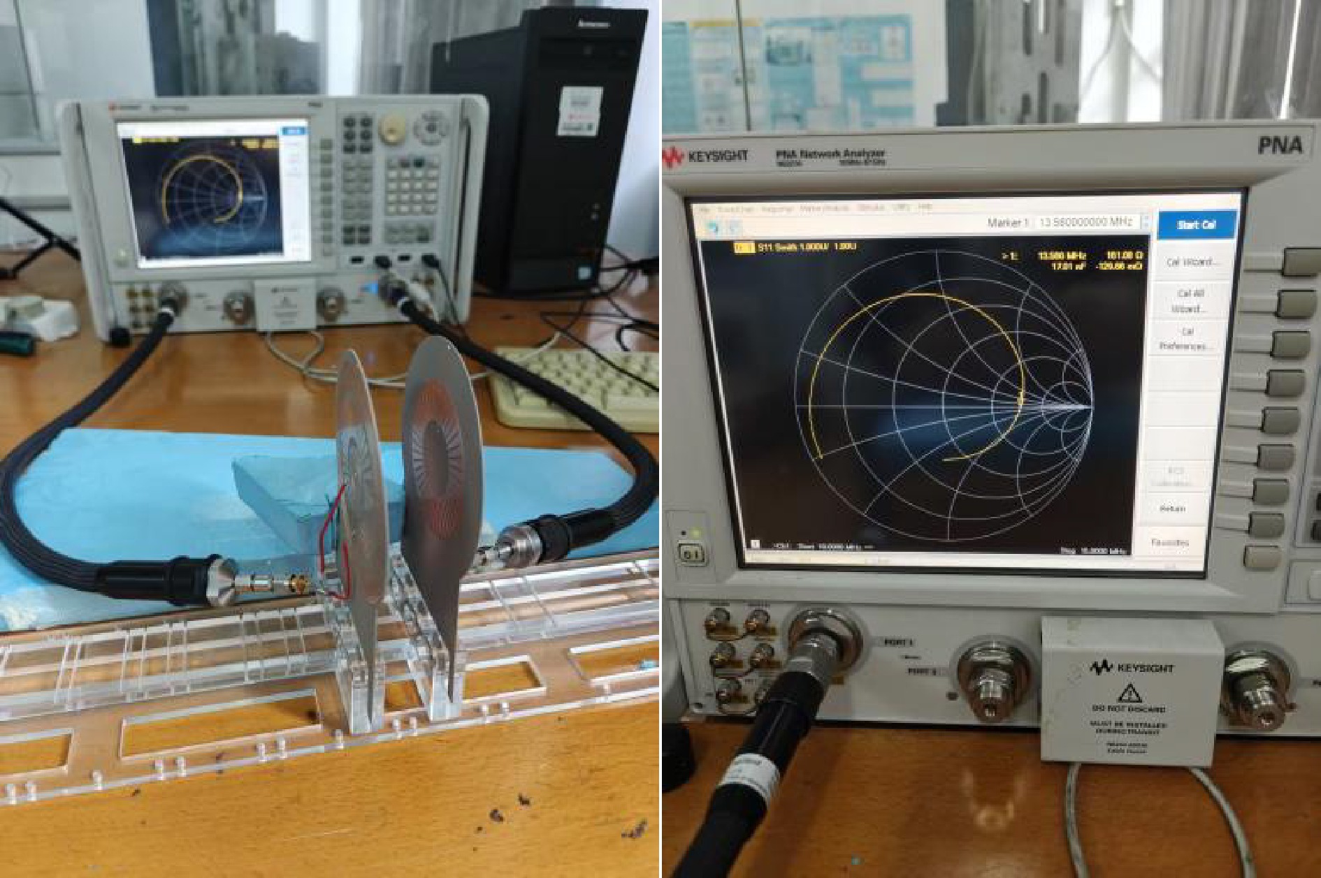
Figure 9.
Experimental setups of the double sided SR LCC coils.
To experimentally verify the load-independent constant-current characteristic discussed, and the insensitivity of the resonant frequency to coupling variations, an AC-AC experimental setup was established using an oscilloscope and an AC power source. Accurate waveform acquisition at the operating frequency of 13.56 MHz was ensured by calibrating the oscilloscope's voltage and current probes with a standard AC resistor and a deskew fixture (Keysight U1880A). This calibration effectively eliminated phase deviations and ensured consistency between the measured and actual voltage–current values, thereby guaranteeing precise waveform measurement.
The AC-AC experimental system consisted of an AC power source (QX-ASA100M), a pair of coupled coils, and an adjustable AC load, as illustrated in Fig. 10. To validate the constant-current output property, the primary LCC SR coil was driven by a constant input voltage of 45 V. The transmitted power can be calculated using the following formula:
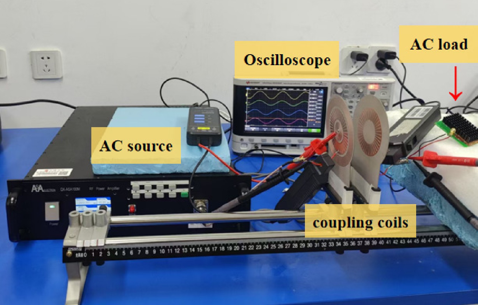
Figure 10.
AC-AC experimental setup of the SR coil IPT system with LCC-LCC compensation characteristics.
$ \overline{P}=\dfrac{1}{T}\int_{0}^{T}P(t)dt $ (21) where,
$ P(t)=u(t)\cdot i(t)={U}_{0}{I}_{0}\cos (\omega t+\varphi )\cos (\omega t) $ (22) The measured input and output voltage-current waveforms of the proposed IPT system at an AC load of 50 Ω are shown in Fig. 11.
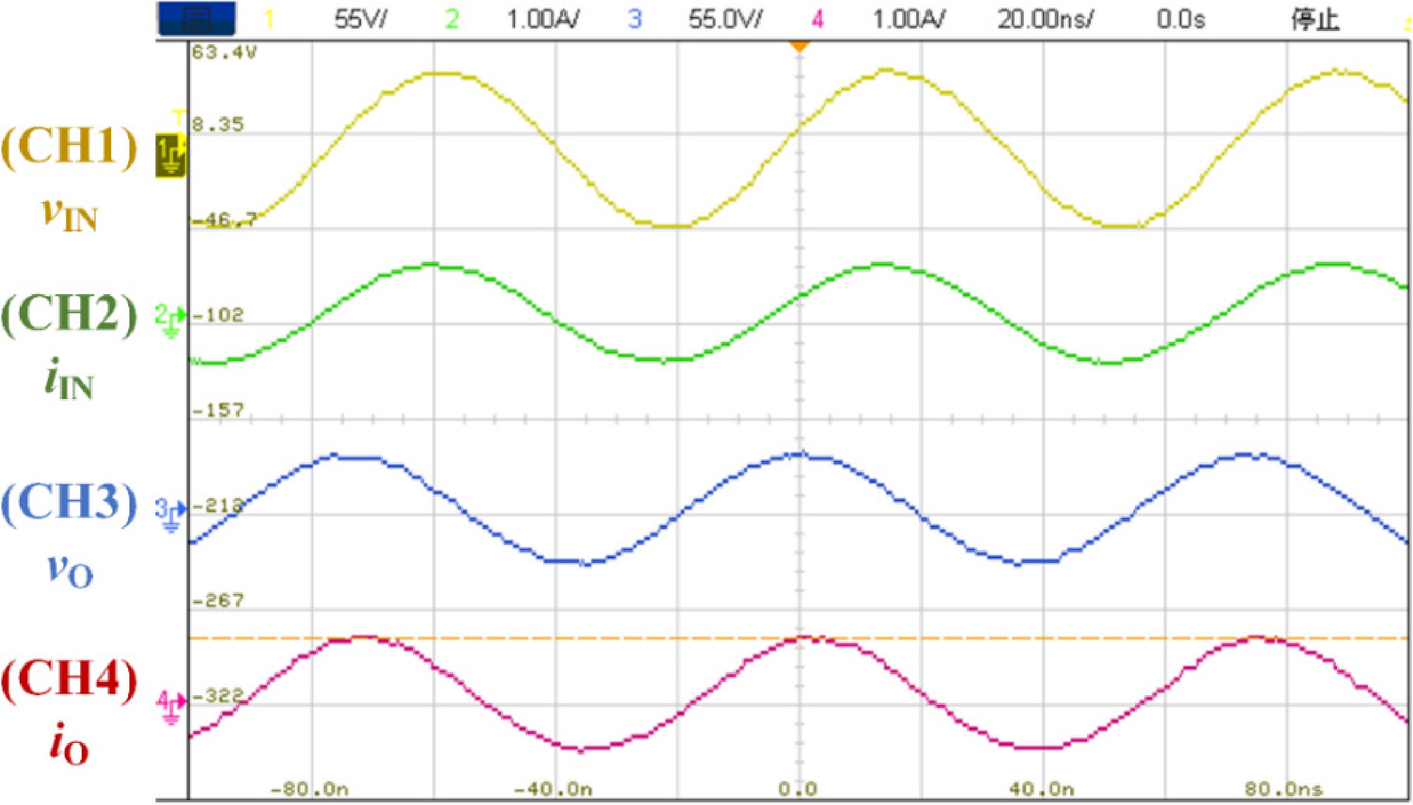
Figure 11.
Measured waveforms on the oscilloscope of the proposed IPT system with an AC load of 50 Ω.
When the AC load was fixed at 50 Ω, Fig. 12a presents the variation of the input voltage–current phase difference with changes in the vertical spacing (dv) between the coils, under conditions where both dv and the lateral offset (dl) were initially zero. Figure 12b depicts the variation in phase difference with dl when dv was maintained at 35 mm. The phase difference remained nearly constant in both cases, indicating that the SR coil system employing LCC-LCC compensation exhibits resonant-frequency independence from the coupling coefficient.
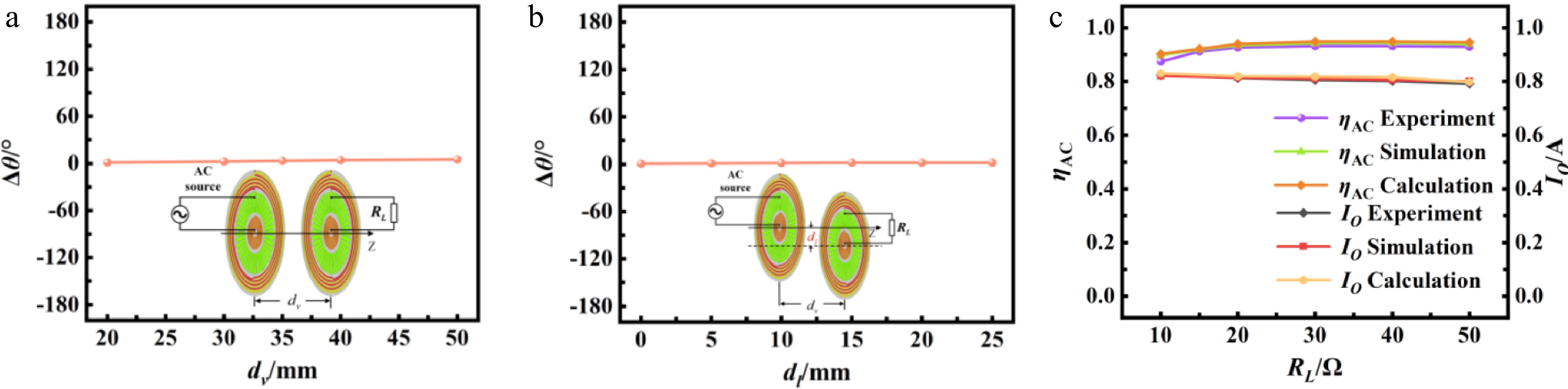
Figure 12.
(a) $ \Delta \theta $ with changes in $ {d}_{v} $. (b) $ \Delta \theta $ with changes in $ {d}_{l} $ at a fixed $ {d}_{v} $ of 35 mm. (c) Transmission efficiency and output current with respect to the different $ {R}_{L} $.
When the AC load varied from 10 to 50 Ω, the output current amplitude decreased slightly from approximately 0.82 to 0.79 A, corresponding to a current fluctuation ratio of only 3.7%. This observation verifies that the SR coil with LCC-LCC compensation achieves an approximately constant-current output characteristic. As shown in Fig. 12c, the AC efficiency (ηAC) remained above 78% across the 10–50 Ω load range, and reached a maximum of 91% at a load of 50 Ω.
-
This paper proposes a self-resonant coil structure based on a double-sided LCC compensation topology, which addresses the limitations of conventional low-order compensation networks. Compared with the LCC-S compensation topology, the proposed design exhibits superior constant-current characteristics, making it more suitable for inductive power transfer (IPT) applications such as wireless charging of electric vehicles and batteries. In contrast to the S–S compensated structure, the proposed topology eliminates the risk of excessive no-load current that may damage the front-end circuit. Moreover, unlike the P–P compensated configuration, its resonant frequency remains nearly unchanged under variations in the coupling coefficient. The system also achieves efficient power transfer over a wide load range, demonstrating excellent practical applicability. Most importantly, compared with traditional double-sided LCC structures that rely on discrete lumped components, the proposed design adopts a self-resonant coil configuration. This approach preserves the favorable AC characteristics of the conventional double-sided LCC topology while significantly reducing system volume, providing a promising technical solution for space-constrained IPT applications.
-
In this paper, a novel SR coil–based compensation structure with LCC-LCC characteristics was proposed. The design integrates the required compensation elements as distributed parameters within the primary coil on a single dielectric substrate, achieving a compact, stable, and highly integrated configuration. The proposed structure effectively combines the advantages of SR coils while overcoming the limitations of traditional low-order series and parallel compensation schemes that cannot simultaneously ensure high stability and safety. Theoretical analysis and experimental verification confirmed that the proposed LCC-LCC compensated SR coil IPT system achieves an approximately constant output current independent of the AC load, maintains high AC-AC transmission efficiency over a wide load range, and exhibits a resonant frequency that is independent of the coupling coefficient. Furthermore, the system ensures safe operation even under no-load conditions without imposing stress on the primary power source. Experimental results demonstrated a maximum power transfer efficiency of 91% at a 35 mm air gap, validating the system's high efficiency, robustness, and practical potential for wireless power transfer applications.
This research was funded by National Natural Science Foundation of China (Grant No. 52207214).
-
The authors confirm contribution to the paper as follows: study conception and design: Yi ZX, Yao YH, Zhang QF; data collection: Yi ZX, Yao YH, Zeng D; analysis and interpretation of results: Yao YH, Li ML; draft manuscript preparation: Yi ZX, Yao YH. All authors reviewed the results and approved the final version of the manuscript.
-
The datasets generated during and/or analyzed in the current study are available from the corresponding author upon reasonable request.
-
No conflict of interest exists in the submission of this manuscript, and manuscript is approved by all authors for publication.
- Copyright: © 2026 by the author(s). Published by Maximum Academic Press, Fayetteville, GA. This article is an open access article distributed under Creative Commons Attribution License (CC BY 4.0), visit https://creativecommons.org/licenses/by/4.0/.
-
About this article
Cite this article
Yi Z, Yao Y, Zhang Q, Zeng D, Li M. 2026. IPT system with double-sided self-resonant LCC coils. Wireless Power Transfer 13: e024 doi: 10.48130/wpt-0026-0015 

IPT system with double-sided self-resonant LCC coils
- Received: 21 November 2025
- Revised: 02 February 2026
- Accepted: 10 April 2026
- Published online: 26 August 2026
Abstract: Self-resonant (SR) coils employ distributed compensation components in place of lumped components, enabling efficient power transfer and high integration. However, existing SR coils are restricted to four low-order compensation networks: SS, SP, PS, and PP. The higher-order double-sided LCC compensation topology has proven superior. Unfortunately, no pair of SR coils that can implement the double-sided LCC compensation topology has been available. This paper proposes an IPT system with double-sided self-resonant LCC coils, which integrates the necessary compensation components with the main coil in a distributed manner on a single substrate, eliminating the need for lumped elements. Formulas for resonant frequency, power transfer efficiency (PTE), output current, and power are provided. Advantageously, the proposed IPT system offers four benefits: constant current output independent of AC load, high PTE, independence of resonant frequency from coupling coefficients, and no damage to the front-end power supply during no-load operation. These advantages are experimentally demonstrated, achieving a PTE of 91% between coils at a 35 mm gap.
-
Key words:
- Self-resonant coil /
- Inductive power transfer /
- LCC