


-
Wireless power transfer (WPT) technology has been rapidly developed due to its high reliability, safety, and convenience, and has been widely researched and applied in fields such as rail transit, portable electronic devices, and implantable medical devices[1−3]. In a WPT system, the transmission performance is dramatically reduced with the increase of transmission distance to receiver radius ratio (known as the distance-to-radius ratio). Therefore, in scenarios where the volume of the receiver is strictly limited, it is difficult to efficiently transmit power to miniature devices over long distances[4,5]. As a result, the contradiction between transmission distance and coupling coil volume has always limited the application scenarios of this technology, each advancement in extending the transmission distance has the potential to bring significant innovation to this field[6−9]. Therefore, achieving long-distance wireless power transfer with a miniature receiver, also known as high distance-to-radius ratio wireless power transfer, is one of the current research focuses.
In terms of enhancing the distance of wireless power transfer technology, the Massachusetts Institute of Technology (USA) has applied beamforming technology to wireless power transfer systems, controlling the directional transmission of magnetic fields by adjusting the amplitude and phase of the current in each transmitter, thereby improving the transmission distance[10−12]; Tiangong University (China) has studied the influence of coil internal resistance and quality factor on transfer power from the asymmetric coupling coil, thereby achieving an improvement in transmission distance[13−14]; the Daegu Gyeongbuk Institute of Science and Technology (South Korea) proposed the advantages of a magnetic independent transmitter in multiple-input single-output systems. Magnetic field focusing can be achieved by simply adjusting the amplitude of the voltage source of the transmitter without phase adjustment. However, multiple exciting sources are required, and the high cost and large mass of the overall structure can severely limit its practical application scenarios[15]; the Korea Maritime and Ocean University (South Korea) proposed a coupling structure that includes multiple transmitting coils, the transmitter consists of a planar arrangement of multiple transmitting coils, each matched with an excitation source corresponding to the number of coils, the effect of the number of coils on the transmission distance is also studied. However, the use of multiple exciting sources results in higher design costs for the system[16].
The existing research works have explored methods to improve the transmission distance of WPT systems, such as current and voltage control, coupling coil design, and parameter optimization. However, there is little mention of the design of long-distance wireless power transfer systems for small receivers. Therefore, a novel multiple coil transmitter is proposed in this paper, which improves the distance-to-radius ratio of wireless power transfer. This structure significantly enhances the magnetic field coverage range and provides long-distance wireless power transfer for miniature devices.
The rest of this article is organized as follows: first, the design of the transmitting coil structure is given, and the high distance-to-radius ratio WPT system is also theoretically analyzed; second, the parameters of the proposed transmitting coil are optimized through simulation; finally, the experimental results of the proposed high distance-to-radius ratio WPT system are presented.
-
The planar arrangement of multiple transmitting coils can slightly improve the transmission distance of WPT systems. However, the improvement in transmission distance is very limited because most transmitting and receiving coils are not coaxial[17]. The stability of efficiency during variations in transmission distance can be enhanced with a conical coil structure[18], but the axial magnetic field strength remains relatively weak due to the absence of coils at the center that generate a magnetic field, resulting in a shorter transmission distance. The edge coils of the planar arrangement of multiple transmitting coils are tilted to form a conical structure so that the edge coils are aligned with the receiving coil in a facing configuration. This arrangement forms a linked magnetic-concentrating umbrella-shaped (LMU) multi-coil structure, as illustrated in Fig. 1a. This design not only strengthens the magnetic field intensity in the central region of the conical coil but also resolves the issue of limited transmission distance improvement associated with non-coaxial alignment of the transmitting coils with the receiving coil in a planar arrangement.
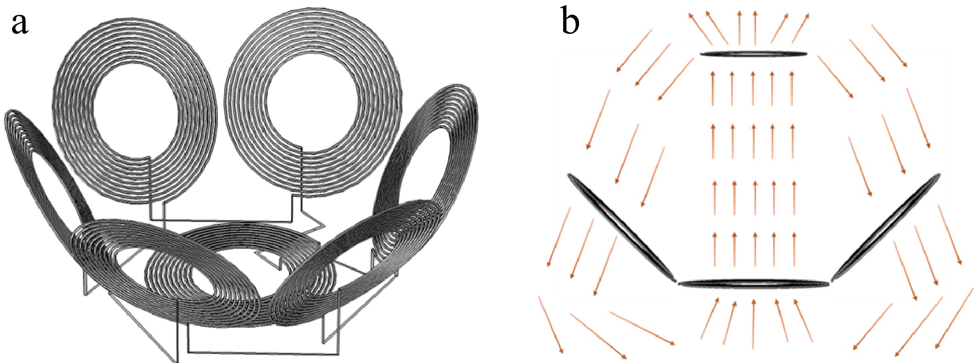
Figure 1.
(a) Structure of the linked magnetic-concentrating umbrella-shaped transmitting coil. (b) Schematic diagram of magnetic field enhancement in LMU structure.
The winding direction of the central coil in the LMU transmitter is opposite to that of the edge coils. The opposing magnetic field directions create complementary pathways between the magnetic fields of the central and edge coils, as shown in Fig. 1b, allowing the magnetic field emitted outward from one coil to loop back in the opposite direction through its adjacent coil. This increases the density of the magnetic flux lines, thereby enhancing the magnetic field. This structure addresses the issue of low magnetic flux regions that occur with conical coils during magnetic field excitation, achieving an enhancement of the electromagnetic field and extending the distance of power transfer.
The high distance-to-radius ratio wireless power transfer system is shown in Fig. 2. Similar to traditional asymmetric two-coil systems, the high-frequency energy generated by an RF power source at the transmitting terminal is delivered to a directly connected LMU transmitting structure, which converts the high-frequency electrical power into a high-frequency electromagnetic field. This field is further wirelessly coupled to a receiving coil, thus transmitting the electromagnetic power. The receiving coil transforms the received electromagnetic field into electrical power, which is rectified and delivered to the load. The characteristic of the high distance-to-radius ratio WPT system is that it enhances the coverage area of the electromagnetic field through magnetic field focusing and superposition, thereby increasing the transmission distance.
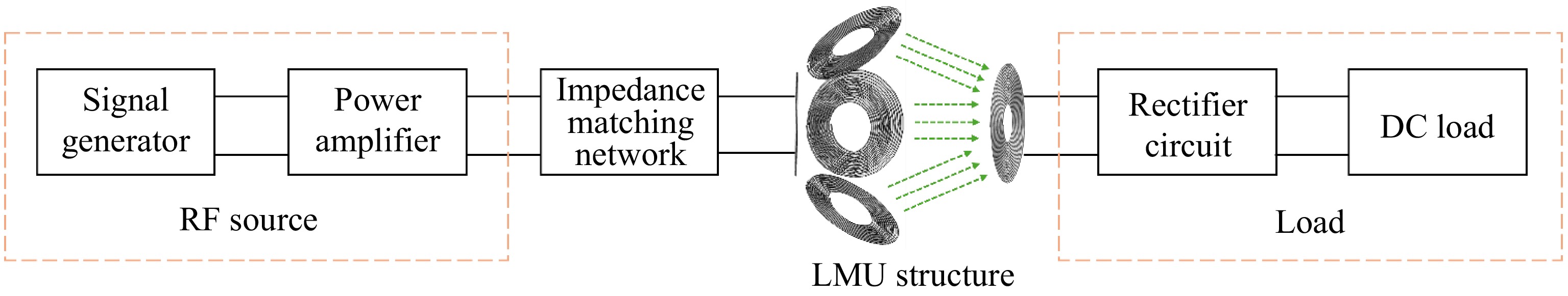
Figure 2.
High distance-to-radius ratio WPT system.
First, an equivalent circuit model for the high distance-to-radius ratio wireless power transfer system is established, as shown in Fig. 3. Assume that the receiver is the nth coil, then the entire transmitting structure consists of (n–1) transmitting sub-coil, including a central coil and (n–2) edge coils. In Fig. 1, Ri and Li represent the internal resistance and inductance of the ith transmitting sub-coil, respectively; Ls denotes the compensating inductance; Cs represents the compensating capacitance, and Cp is the tuning capacitance of the transmitting coil; Rn and Ln indicate the internal resistance and inductance of the receiving coil, respectively; CL represents the tuning capacitance at the receiving end, and RL denotes the equivalent load resistance; and Mi,j represents the mutual inductance between the ith and j-th transmitting sub coil, while Mi,n indicates the mutual inductance between the i-th transmitting sub coil and the receiving coil, i, j = 1, 2, …, n–1.
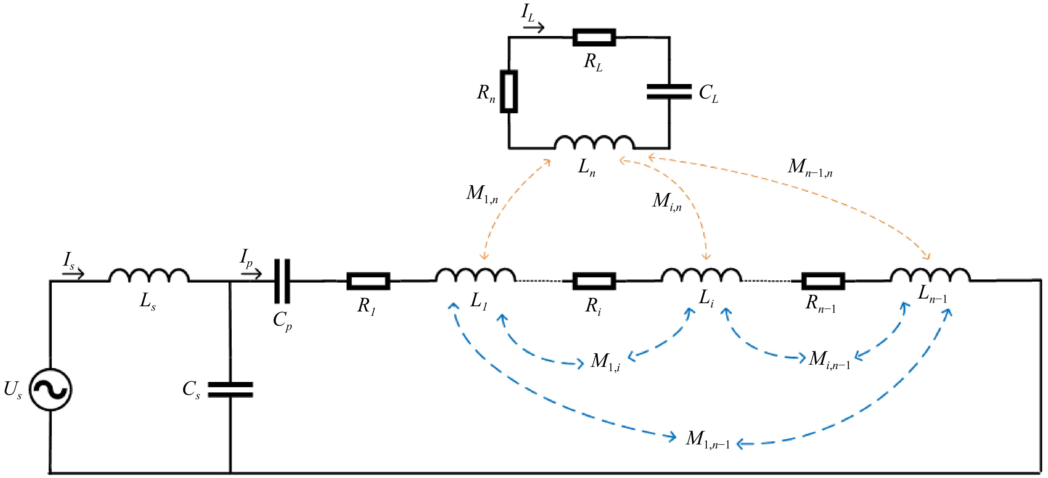
Figure 3.
Equivalent circuit model of high distance-to-radius ratio WPT system.
Based on the equivalent circuit, three Kirchhoff's voltage law equations can be formulated using the mesh current method. The matrix representation of these equations is given as follows:
$ \left[\begin{array}{ccc}{Z}_{s}& -{Z}_{cs}& 0\\ -{Z}_{cs}& {Z}_{p}& {Z}_{\mathrm{M}\mathrm{i}\mathrm{n}}\\ 0& {Z}_{\mathrm{M}\mathrm{i}\mathrm{n}}& {Z}_{L}\end{array}\right]\left[\begin{array}{c}{I}_{s}\\ {I}_{p}\\ {I}_{L}\end{array}\right]=\left[\begin{array}{c}{U}_{s}\\ 0\\ 0\end{array}\right] $ (1) where,
$ {Z}_{s}=j\omega {L}_{s}+\frac{1}{j\omega {C}_{s}} $ $ {Z}_{Cs}=\frac{1}{j\omega {C}_{s}} $ $ {L}_{i\Sigma }={\sum }_{i=1}^{m}{L}_{i}+2{\sum }_{i=1}^{m-1}{\sum }_{j=i+1}^{m}{M}_{ij}\left(n-1\ge m\ge 2\right) $ $ {R}_{i\Sigma }={\sum }_{i=1}^{m}{R}_{i} $ $ {Z}_{p}= \frac{1}{j\omega {C}_{s}}+ \frac{1}{j\omega {C}_{p}}+j\omega {L}_{i\Sigma }+{R}_{i\Sigma } $ $ {M}_{in}={\sum }_{i=1}^{m}{M}_{i,n} $ $ {Z}_{Min}=-j\omega {M}_{in} $ $ {Z}_{L}=j\omega {L}_{n}+\frac{1}{j\omega {C}_{n}}+{R}_{n}+{R}_{L} $ $ {C}_{L}=\dfrac{1}{{\omega }^{2}{L}_{n}} $ (2) The compensation circuit and tuning capacitor on the transmission side should satisfy the following relationship:
$ j\omega {L}_{s}+\dfrac{1}{j\omega {C}_{s}}=0 $ (3) $ \dfrac{1}{j\omega {C}_{p}}+j\omega \left({\sum }_{i=1}^{m}{L}_{i}+2{\sum }_{i=1}^{m}{\sum }_{j=1}^{i-1}{M}_{ij}-{L}_{s}\right)=0 $ (4) By substituting the above formula into the above matrix equation, Eqn (5) can be obtained as follows:
$ \left[\begin{array}{ccc}0& j\omega {L}_{s}& 0\\ j\omega {L}_{s}& {R}_{i\Sigma }& -j\omega {M}_{i,n}\\ 0& -j\omega {M}_{i,n}& {R}_{n}+{R}_{L}\end{array}\right]\left[\begin{array}{c}{I}_{s}\\ {I}_{p}\\ {I}_{L}\end{array}\right]=\left[\begin{array}{c}{U}_{s}\\ 0\\ 0\end{array}\right] $ (5) Equation (1) can be used to derive the load received power and system transmission efficiency as follows:
$ {P}_{L}={I}_{L}^{2}{R}_{L}=\dfrac{{\left(\sum _{i=1}^{m}{M}_{i,n}\right)}^{2}{R}_{L}}{{L}_{s}^{2}{\left({R}_{n}+{R}_{L}\right)}^{2}} $ (6) $ \eta =\dfrac{{\left|{I}_{L}\right|}^{2}{R}_{L}}{{\left|{I}_{P}\right|}^{2}\sum _{i=1}^{m}{R}_{i}+{\left|{I}_{L}\right|}^{2}\left({R}_{n}+{R}_{L}\right)}=\dfrac{\dfrac{{\omega }^{2}{\left(\sum _{i=1}^{m}{M}_{i,n}\right)}^{2}}{{\left({R}_{n}+{R}_{L}\right)}^{2}}{R}_{L}}{\sum _{i=1}^{m}{R}_{i}+\dfrac{{\omega }^{2}{\left(\sum _{i=1}^{m}{M}_{i,n}\right)}^{2}}{\left({R}_{n}+{R}_{L}\right)}} $ (7) From Eqn (7), it can be observed that the system efficiency is primarily influenced by the mutual inductance between the transmitting and receiving coils, as well as the resistances at the transmitting and receiving ends. It is independent of the mutual inductance between the transmitter sub-coils. The derivation process of the mutual inductance is as follows:
Assume that the two circular coils are coaxial. The mutual inductance is then calculated using the Norman formula[19]. First, the coils are parameterized as follows:
$ M=\dfrac{\mu_0N_1N_2}{4\pi}\oint_{C_1}\oint_{C_2}\dfrac{\mathit{\mathbf{d}\mathbf{l}}_1\cdot\mathit{\mathbf{d}\mathbf{l}}_2}{R} $ (8) In this formula, μ0 represents the permeability of free space, while N1 and N2 denote the number of turns of the transmitting and receiving coils, respectively. dl1 and dl2 represent the line elements of the two coils, and R is the distance between dl1 and dl2. The integration path follows the closed loops C1 and C2 of the two coils. A global coordinate system is established to calculate dl1, dl2, and R:
$ {\mathbf{r}}_{1}=({r}_{1}\mathrm{c}\mathrm{o}\mathrm{s}{\phi }_{1},{r}_{1}\mathrm{s}\mathrm{i}\mathrm{n}{\phi }_{1},0) $ (9) $ {\mathbf{r}}_{2}=({r}_{2}\mathrm{c}\mathrm{o}\mathrm{s}{\phi }_{2},{r}_{2}\mathrm{s}\mathrm{i}\mathrm{n}{\phi }_{2},d) $ (10) $ {\mathbf{d}\mathbf{l}}_{1}=(-{r}_{1}\mathrm{s}\mathrm{i}\mathrm{n}{\phi }_{1},{r}_{1}\mathrm{c}\mathrm{o}\mathrm{s}{\phi }_{1},0)d{\phi }_{1} $ (11) $ {\mathbf{d}\mathbf{l}}_{2}=(-{r}_{2}\mathrm{s}\mathrm{i}\mathrm{n}{\phi }_{2},{r}_{2}\mathrm{c}\mathrm{o}\mathrm{s}{\phi }_{2},0) $ (12) At this point, the formula for calculating mutual inductance is:
$ M=\dfrac{{\mu }_{0}{N}_{1}{N}_{2}\pi {\mathrm{r}}_{1}{\mathrm{r}}_{2}}{2}{\int }_{0}^{2\pi }\dfrac{\cos\phi d\phi }{\sqrt{{r}_{1}^{2}+{r}_{2}^{2}+{d}^{2}-2{r}_{1}{r}_{2}\cos\phi }} $ (13) where,
$ \phi ={\phi }_{1}-{\phi }_{2} $ $ {k}^{2}=\dfrac{4{\mathrm{r}}_{1}{\mathrm{r}}_{2}}{{\left({\mathrm{r}}_{1}+{\mathrm{r}}_{2}\right)}^{2}+{d}^{2}} $ (14) The integration result can be expressed as the first and second types of fully elliptic integrals:
$ M={\mu }_{0}{N}_{1}{N}_{2}\sqrt{{r}_{1}{r}_{2}}\left.\left[\dfrac{2}{k}\left.\left(K\left(k\right)-E\left(k\right)\right.\right)\right.\right] $ (15) The elliptic integral can be expressed as:
$ K\left(k\right)={\int }_{0}^{\pi /2}\dfrac{d\alpha }{\sqrt{1-{k}^{2}{\mathrm{s}\mathrm{i}\mathrm{n}}^{2}\alpha }} $ (16) $ E\left(k\right)={\int }_{0}^{\pi /2}\sqrt{1-{k}^{2}{\mathrm{s}\mathrm{i}\mathrm{n}}^{2}\alpha }d\alpha $ (17) Considering the possible radial (
$ \delta ,\varepsilon $ $ \theta $ $ {M}_{f}=M\cos \theta {e}^{-\frac{{\delta }^{2}+{\varepsilon }^{2}}{2{d}^{2}}} $ (18) Equations (15) and (18) can be used to calculate the total mutual inductance between the transmitting and receiving coils. Assuming a set of parameters to verify the accuracy of formula derivation: the radii of the two coils are 10 and 30 mm, with 10 turns each. The radial offset in the x and y directions is 20 mm, and the distance between the two coils is 80 mm, one of the coils is tilted 45° relative to the z-axis. At this point, the simulation shows that the mutual inductance between the two coils is 3,168 nH, and the formula calculates the mutual inductance to be 3,005 nH, with a relative error of 5.1%, verifying the accuracy of the theoretical derivation. However, the theoretical analysis of its results is not intuitive enough as it belongs to the transcendental function, therefore, the transmission efficiency of the LMU structure can be studied through simulation.
-
The transmission characteristics of the LMU structure are investigated in detail through simulation, and the parameters will be designed and optimized.
Simulations of high distance-to-radius ratio transmitting coil structures
-
The optimal size of the edge coils in high distance-to-radius ratio is first determined through the transfer efficiency of different conical transmitting coil sizes at various distance-to-radius ratios due to the conical shape of the edge coils in the LMU structure. The receiving coil is a circular planar coil with a radius of 10 mm.
The relationship between transmitting coil radius and power transfer efficiency at different transmission distances is shown in Fig. 4. The transfer efficiency initially increases and subsequently decreases with the growing size of the transmitting coil, and the rate of variation diminishes significantly around the point of maximum efficiency. Moreover, the optimal distance-to-radius ratio rises from 1:2 to 3:1 as the transmission distance increases from 5 to 30 mm, indicating that the optimal radius of the transmitting coil tends to increase with greater transmission distances. Across the entire range of transmission distances, the transfer efficiency difference between distance-to-radius ratios of 2.5:1 and 3:1 remains below 3%. Furthermore, the transfer efficiency variation stays within 1% when the transmitting and receiving coil sizes are maintained at an approximate 3:1 ratio, even when the transmitting coil size fluctuates by ± 10 mm. These findings suggest that a 3:1 size ratio between the edge coil and the receiving coil yields optimal transfer efficiency, particularly at high distance-to-radius ratios.
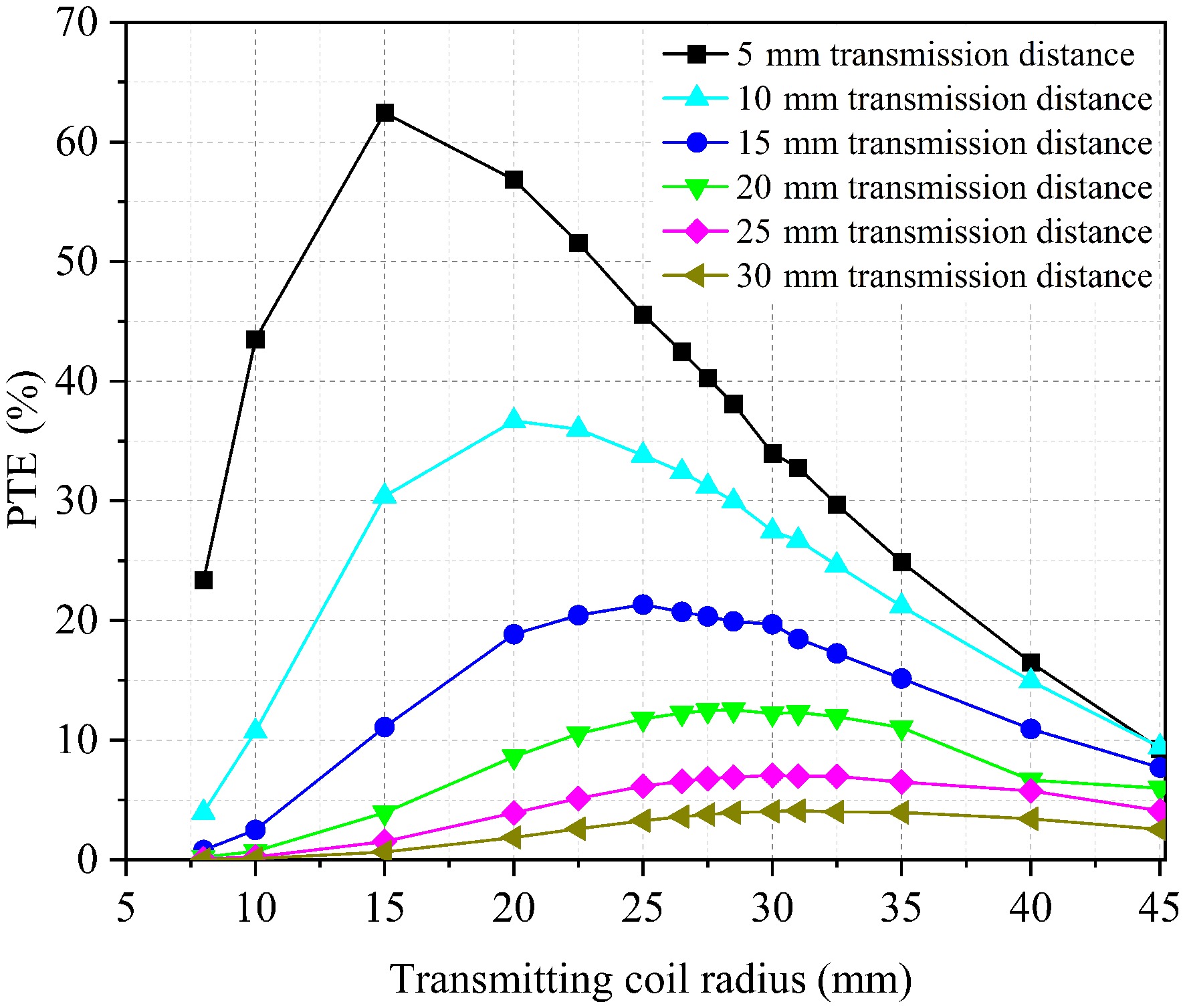
Figure 4.
Relationship between transmitting coil radius and power transfer efficiency at different transmission distance.
The specific configuration of the coil was designed based on the study of structural size. Four different structures were proposed in the coil design phase. The edge coil in Fig. 5a is a hybrid winding array coil that can effectively concentrate the magnetic field generated by the coil at the center of the internal small coil, thereby enhancing the magnetic field strength; Fig. 5b shows a single-layer LMU transmitting coil, which increases the magnetic field strength by superimposing the magnetic fields of the edge coil and the center coil; Fig. 5c shows the LMU transmitting coil with four-coil configuration. It can effectively enhance the transfer power and efficiency, as well as increases the transmission distance; Fig. 5d increases the number of center coils. The dual-layer center coils not only improve the transfer power but the additional center coils also function as active relay coils for the original center coil to increase the transmission distance.
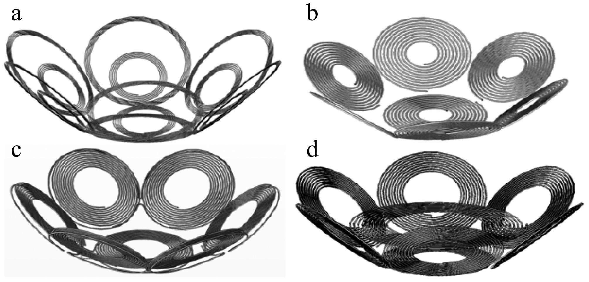
Figure 5.
Schematic diagrams of coil structure designs. (a) Hybrid winding array coil. (b) Single-layer LMU transmitting coil. (c) LMU transmitting coil with four-coil configuration. (d) Dual-layer LMU transmitting coil.
The edge coils in the above four structures are all connected in series to ensure that the current direction of each sub-coil is consistent, while it flows in the opposite direction to that of the center coil. This way, the opposite direction of the magnetic field generated by the edge coils and the central coil is conducive to the mutual enhancement of the magnetic field. The coil structure parameters are shown in Table 1.
Table 1. Parameters of high distance-to-radius ratio WPT system.
Parameter Symbol Value Number of turns of transmitting coil N1 10 Number of turns of receiving coil N2 10 Radius of transmitting sub-coil r1 30 mm Radius of receiving coil r2 10 mm Wire diameter of transmitting coil a1 0.4 mm Wire diameter of receiving coil a2 0.2 mm Turns spacing of the transmitting coil g1 2.1 mm Turns spacing of the receiving coil g2 0.7 mm Number of edge coils N 6 Frequency F 6.78 MHz Load resistance R 50 Ω The transmission performance of four structures is shown in Fig. 6. The hybrid winding array coil is the least effective due to its magnetic field being concentrated at the center of the interior, while this improves transfer efficiency at short distances, the efficiency declines rapidly at medium distances. In contrast, the single-layer LMU transmitting coil achieves higher transfer efficiency at medium to low distance-to-radius ratios, however, its attenuation rate is significant, with efficiency dropping below 35% when the distance-to-radius ratio reaches 7:1. The four-coil LMU transmitting coil extends the transmission distance compared to the two-coil structure, providing a 2% improvement in efficiency. Additionally, the dual-layer LMU transmitting coil further enhances power transfer within a distance-to-radius ratio of 10:1, enabling effective power transfer at higher distance-to-radius ratios.
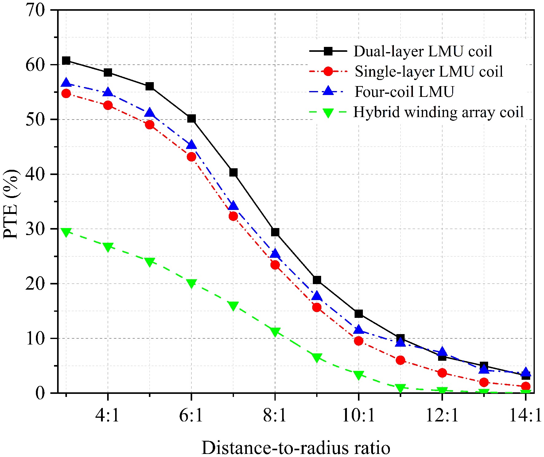
Figure 6.
Relationship between the distance-to-radius ratio of different transmitting coils and transfer efficiency.
To further analyze the underlying reasons, the magnetic field intensity simulation diagrams for the different structures as shown in Fig. 7. These graphs can explain the reasons for efficiency differences by observing the differences in magnetic field strength around the receiving coil. Figures 7a−d are simulation diagrams of magnetic field strength for four types of coil structures with a distance-to-radius ratio of 5:1. In each diagram, the center corresponds to the receiving coil. It can be observed that the magnetic field intensity at the receiving coil aligns well with the efficiency differences of the four coil structures presented in Fig. 6, higher transmission efficiency corresponds to a stronger magnetic field intensity at the receiving coil.
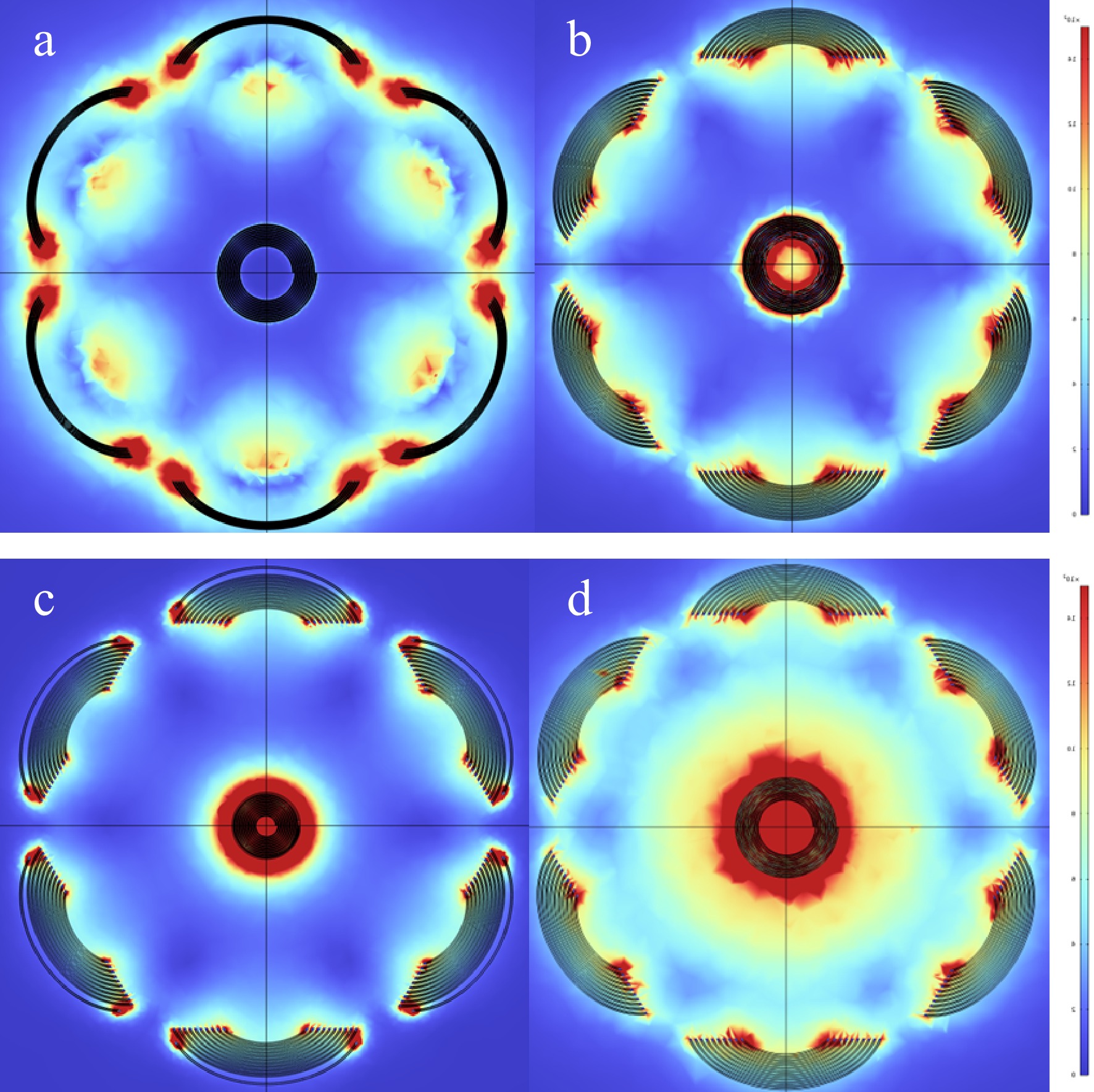
Figure 7.
(a) Magnetic field simulation diagram of hybrid winding array coil. (b) Magnetic field simulation diagram of single-layer LMU transmitting coil. (c) Magnetic field simulation diagram of LMU transmitting coil with four-coil configuration. (d) Magnetic field simulation diagram of Dual-layer LMU transmitting coil.
Optimization of high distance-to-radius ratio transmitting coil structure
-
For the LMU transmitting coil, the edge coils are arranged in a surrounding manner at the edge of the central coil. Since the size of the central coil is maintained at a 3:1 ratio with the receiving coil, this limits the size selection of the edge coils, and the size constraints also affect the number of sub-coils. In addition, the inclination angle of the edge coils also affects the magnetic coupling ability of the transmitting structure. Therefore, it is necessary to study and analyze the number and inclination angle of the edge coils.
The effect of the taper angle on power transfer efficiency is shown in Fig. 8, the efficiency shows a declining trend as the distance-to-radius ratio increases. The rate of decline becomes more gradual at first, then steeper as the distance-to-radius ratio increases. Therefore, it can be concluded that the LMU transmitting coil is better in a short distance. For the edge coils, the transfer efficiency first increases and then decreases as the taper angle varies from 0° to 75°. The transfer efficiency reaches its maximum point at a taper angle of 60° when the distance-to-radius ratio is small. As the distance-to-radius ratio increases, the transfer efficiency fluctuates within ± 3% for taper angles of 45°, 60°, and 30° when the distance-to-radius ratio exceeds 10:1, with the difference being less than 2% at long distances. Therefore, the transmission performance is better when the taper angle of the edge coil is 45°.
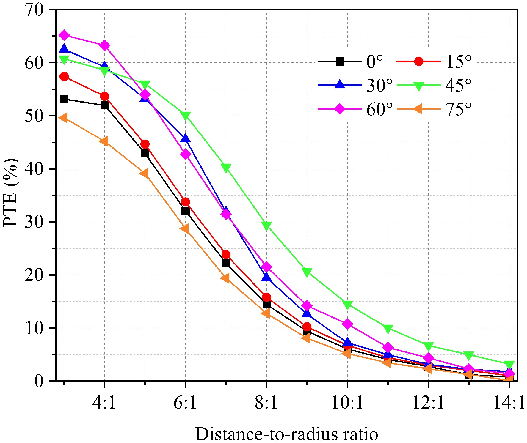
Figure 8.
Relationship between the distance-to-radius ratio of different taper angles and power transfer efficiency.
Figure 9 illustrates that transfer efficiency initially increases and subsequently decreases as the number of edge coils increases under a constant distance-to-radius ratio. Furthermore, the transfer efficiency of the LMU structure with six edge coils is equivalent to that with seven edge coils at a distance-to-radius ratio of 5:1, and its transfer efficiency exceeds that of other edge coil structures by approximately 5% when the distance-to-radius ratio is greater than 8:1. For high distance-to-radius ratios in WPT systems, increasing the number of edge coils results in minimal efficiency gains (less than 1%). However, with fewer edge coils, the transfer efficiency drops sharply, reaching approximately 5% at a distance-to-radius ratio of 5:1.
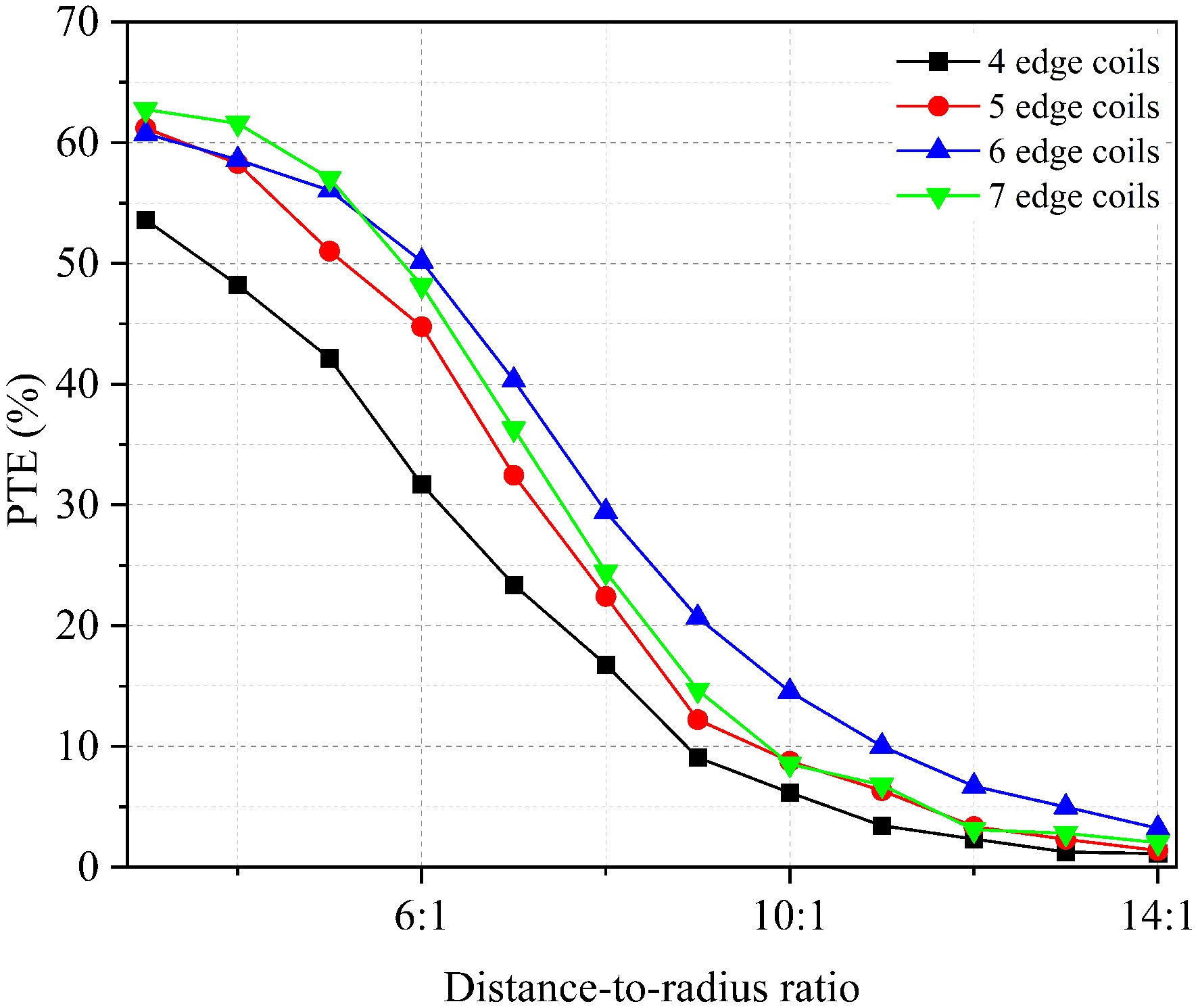
Figure 9.
Relationship between the distance-to-radius ratio and power transfer efficiency with different number of edge coils.
In summary, based on the analysis of the impact of different taper angles and numbers of edge coils on the transfer efficiency at various distance-to-radius ratios, it can be concluded that the LMU transmitting coil structure with six edge coils and a taper angle of 45° is better suited to meet the requirements of high distance-to-radius ratio WPT systems for miniature devices.
-
To verify the transmission performance of the LMU transmitting coil in high distance-to-radius ratio scenarios, a high distance-to-radius ratio WPT experimental system was built and shown in Fig. 10. The coupling structure's load resistance was maintained at 50 Ω and in resonance by connecting an impedance matching system. The system's transfer power and load received power were measured using a high-precision power meter. Based on simulation results, the LMU transmitting coil structure with six edge coils and a taper angle of 45° was constructed. The efficiency trend of the system was analyzed by varying the position and size of the receiving coil. Comparative experiments were also conducted using receiving coils of different sizes.
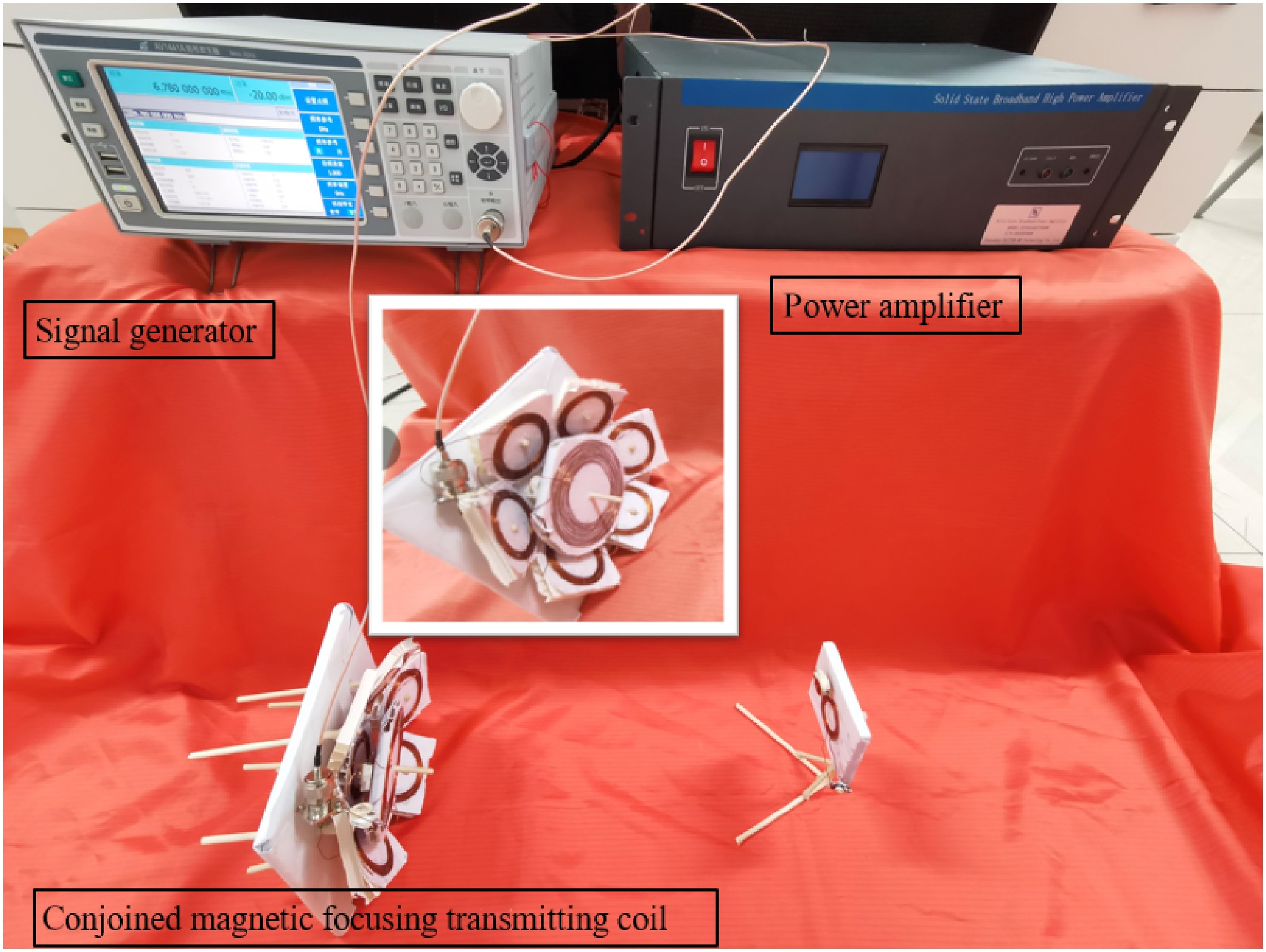
Figure 10.
High distance-to-radius ratio WPT experiment system.
Experiment verification of the LMU transmitting coil structure
-
The parameters of both the transmitting and receiving coils were kept consistent with the simulations, as shown in Table 1. The receiving coil was aligned on the same central axis as the central coil of the LMU transmitting coil.
The transfer efficiency at different distance-to-radius ratios was measured by changing the taper angle of the edge coils. From Fig. 11, the fluctuation pattern of transfer efficiency between simulation and experiment is consistent, showing a downward trend with the increase of distance-to-radius ratio, and the maximum fluctuation can reach 30%. Similarly, the system's transfer efficiency shows a trend of first increasing and then decreasing with changes in the taper angle of the edge coils, attaining a higher transfer efficiency at 45°. Therefore, the LMU structure can maintain a certain level of transfer efficiency for medium to long distances, achieving a high distance-to-radius ratio WPT.
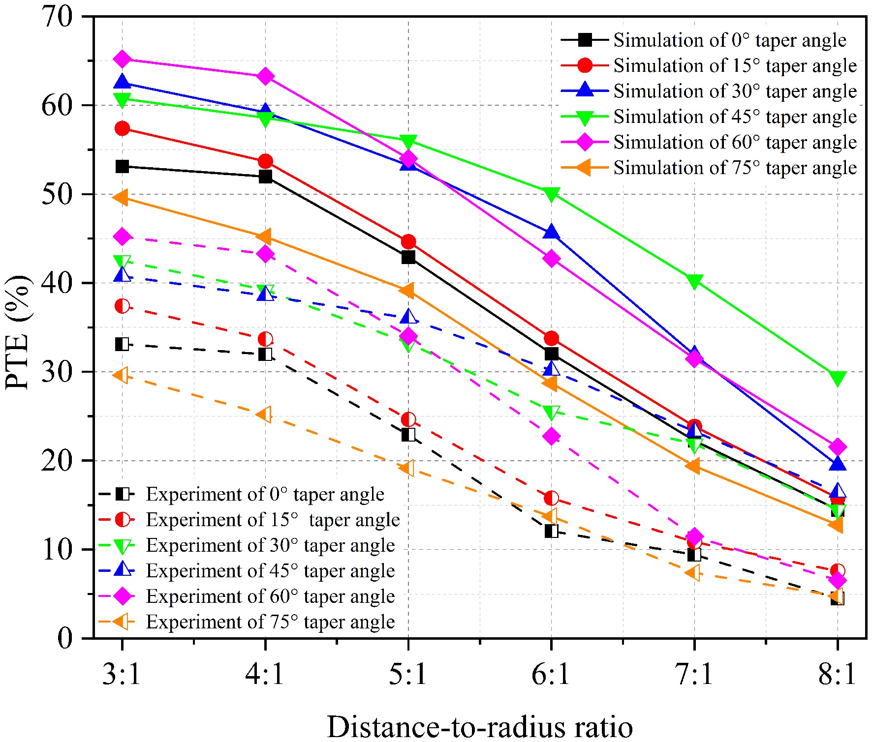
Figure 11.
Comparison of simulation and experimental results of transfer efficiency variation with distance-to-radius ratio at different taper angles of edge coils.
Experimental verification of high distance-to-radius ratio WPT system with different receiving coil sizes
-
The transmission performance of three different sizes of receiving coils was studied under the condition that the parameters of the transmitting coil are consistent with the simulation results. The size and position of the receiving coils are varied while ensuring that the center of the transmitting coil and the center of the receiving coil are aligned along the same central axis. The experimental results are shown in Fig. 12, the overall trend of the impact of transmission distance on transfer efficiency remains unchanged with the increase in the receiving coil size. The transfer efficiency improves at medium to long distances, but the rate of improvement decreases.
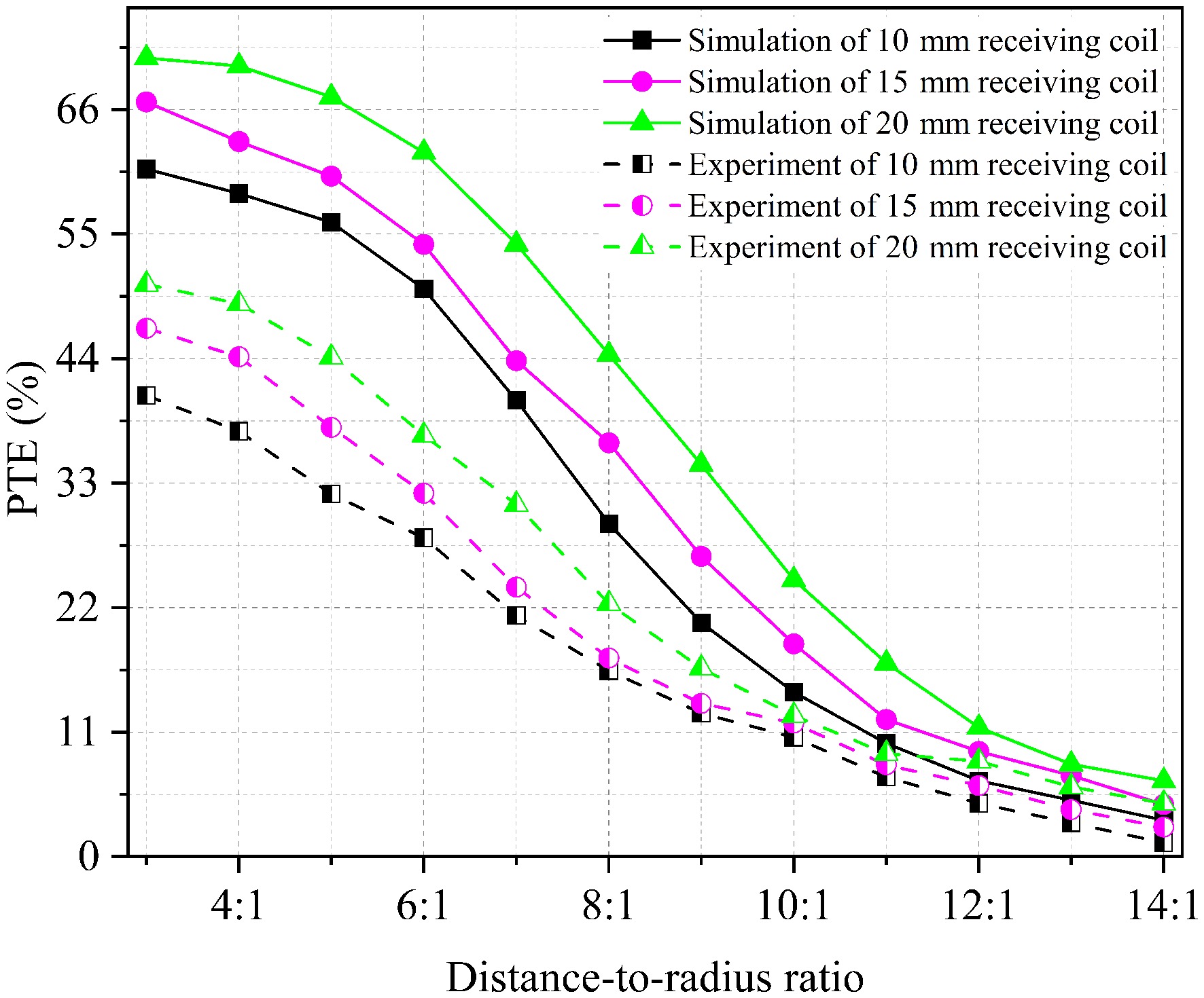
Figure 12.
Comparison of simulation and experimental results of transfer efficiency variation with distance-to-radius ratio at different sizes of receiving coil.
In summary, based on the comparison of simulation and experimental data, it can be seen that the trends of the simulation and experimental curves are in good agreement. However, since the experiment did not account for losses introduced by various measuring instruments and the effects of coil heating, the simulation results are higher than the experimental results. The experiment verified the superiority of the proposed structure in high distance-to-radius ratio WPT scenarios.
Experimental verification of voltage and current waveforms
-
To verify the accuracy of the experimental results, the experimental waveforms of the transmitting and receiving ends is measured. Figure 13a and b show the voltage and current waveforms of the transmitting coil and receiving coil at a distance-to-radius ratio of 8:1 and a frequency of 6.78 MHz, respectively. The blue curve represents the current waveform and the pink curve represents the voltage waveform. The effective voltage and current on the transmitter end were measured at 16.08 V and 1.238 A. In this scenario, the effective output voltage and current were found to be 7.66 V and 0.589 A.
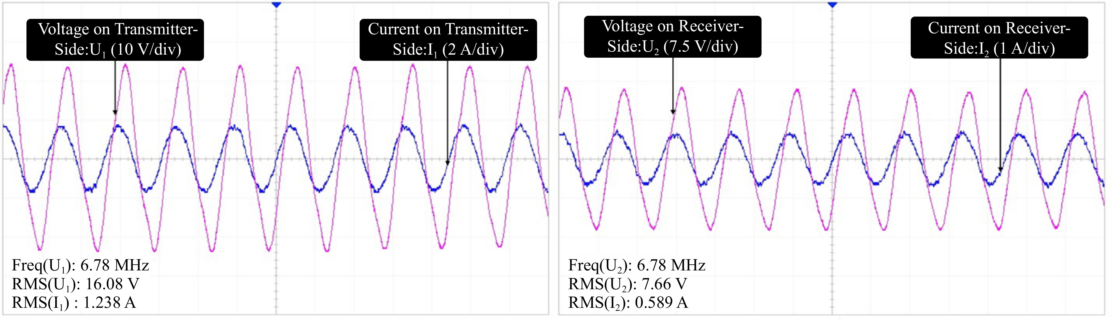
Figure 13.
(a) Voltage and current waveform at the transmitting end. (b) Voltage and current waveform at the receiving end.
To more intuitively reflect the characteristics of the LMU structure, the area ratio of the transmitting and receiving coils, distance-to-radius ratio, transmission power, and transfer efficiency of the LMU structure were compared in Table 2 with those of the single input single output (SISO) system, beamforming system, and dual input single output system. To demonstrate the efficiency improvement of the LMU structure compared to the SISO system, the data of the SISO system were simulated under the same distance-to-radius ratio. The LMU structure proposed in this paper achieves an efficiency improvement of approximately 20% compared to the traditional single input single output system under the same distance-to-radius ratio. When compared to the beamforming method[10], the proposed system significantly reduces the area ratio of the transmitting and receiving coils while maintaining a similar distance-to-radius ratio, power, and efficiency. This reduction enhances the convenience and cost-effectiveness of powering small devices. Additionally, compared to the dual-transmitter single-receiver system[15], the proposed system significantly improves both the distance-to-radius ratio and transfer efficiency, enabling higher transfer efficiency at greater distances.
-
A novel LMU transmitting structure to achieve high distance-to-radius ratio wireless power transfer for miniature devices was proposed in this paper. The relationship between distance-to-radius ratio and transfer efficiency for different transmitting structures is analyzed through simulation, and based on this, a parameter optimization design is conducted. A high-distance-to-radius ratio wireless power transfer system experimental platform was built, and the experimental results show good consistency with the simulation. The following conclusions are drawn:
1. The LMU transmitting coil proposed in this paper employs a reasonable winding method to ensure that the edge coils are wound in the opposite direction to the center coil. The magnetic fields generated by the inner and outer coils mutually reinforce each other and enhance the magnetic field strength on the central axis.
2. For different application scenarios, the optimal distance-to-radius ratio of the LMU transmitting coil can be adjusted by varying the number and taper angle of the edge coils, achieving the highest transfer efficiency.
Based on the experimental results in this paper, the transfer efficiency remains above 22.36% at a distance-to-radius ratio of 8:1. Moreover, the efficiency decreases gradually at a distance-to-radius ratio of 5:1, and the transmitting coil also has high efficiency stability when the transmission distance changes. It is proven that at high distance-to-radius ratios, the linked magnetic-concentrating umbrella-shaped transmitting coil generates a stronger magnetic field, enabling power transfer over greater distances.
This research was partially funded by the Beijing-Tianjin-Hebei Basic Research Cooperation project (24JCZXJC00020), Tianjin Applied Basic and Frontier Technology Research Programme (Natural Science Foundation) Top Project (23JCYBJC00400), and the National Natural Science Foundation of China (52277016).
-
The authors confirm contribution to the paper as follows: study conception and design: Li Y, Gao R; data collection Li Y, Yuan B, analysis and interpretation of results: Li Y, Zhai Y, draft manuscript preparation: Li Y, Gao R, Zhu L; software: Wang H. All authors reviewed the results and approved the final version of the manuscript.
-
The datasets generated during the current study are available from the corresponding author on reasonable request.
-
The authors declare that they have no conflict of interest.
- Copyright: © 2025 by the author(s). Published by Maximum Academic Press, Fayetteville, GA. This article is an open access article distributed under Creative Commons Attribution License (CC BY 4.0), visit https://creativecommons.org/licenses/by/4.0/.
-
About this article
Cite this article
Li Y, Gao R, Yuan B, Zhai Y, Zhu L, et al. 2025. A novel transmitter of high distance-to-radius ratio wireless power transfer for miniature devices. Wireless Power Transfer 12: e015 doi: 10.48130/wpt-0025-0011 

A novel transmitter of high distance-to-radius ratio wireless power transfer for miniature devices
- Received: 26 November 2024
- Revised: 10 March 2025
- Accepted: 24 April 2025
- Published online: 10 June 2025
Abstract: Achieving long-distance wireless power transfer for miniature devices is challenging because the transmission distance is limited by the size of the receiving coil, which must be enlarged to improve range. To solve this problem, a novel transmitter consisting of edge coils and a center coil is proposed in this paper, and the edge coils are placed at an angle relative to the central coil, which are wound in opposite directions to each other to increase the strength of the magnetic field along the central axis through opposite currents. Additionally, the number and taper angle of edge coils are optimized through simulation, and the experiment showed that the proposed structure with six edge coils achieved a transfer efficiency of 22.36% when tilted at 45° at a distance-to-radius ratio of 8:1.
-
Key words:
- Wireless power transfer /
- Miniature devices /
- High distance-to-radius ratio /
- Muti-coil